itemizestditemize
\AggressiveGrasping with a “Soft” Drone:
From Theory to Practice
Abstract
Rigid grippers used in existing aerial manipulators require precise positioning to achieve successful grasps and transmit large contact forces that may destabilize the drone. This limits the speed during grasping and prevents “dynamic grasping”, where the drone attempts to grasp an object while moving. On the other hand, biological systems (e.g., birds) rely on compliant and soft parts to dampen contact forces and compensate for grasping inaccuracy, enabling impressive feats.
This paper presents the first prototype of a soft drone — a quadrotor where traditional (i.e., rigid) landing gears are replaced with a soft tendon-actuated gripper to enable aggressive grasping. We provide three key contributions. First, we describe our soft drone prototype, including electro-mechanical design, software infrastructure, and fabrication. Second, we review the set of algorithms we use for trajectory optimization and control of the drone and the soft gripper; the algorithms combine state-of-the-art techniques for quadrotor control (i.e., an adaptive geometric controller) with advanced soft robotics models (i.e., a quasi-static finite element model). Finally, we evaluate our soft drone in physics simulations (using SOFA and Unity) and in real tests in a motion-capture room. Our drone is able to dynamically grasp objects of unknown shape where baseline approaches fail. Our physical prototype ensures consistent performance, achieving 91.7% successful grasps across 23 trials. We showcase dynamic grasping results in the video attachment.
10(3,0.1) Please cite as follows: J. Fishman, S. Ubellacker, N. Hughes and L. Carlone,
"Aggressive Grasping with a “Soft” Drone: From Theory to Practice"
IEEE/RSJ International Conference on Intelligent Robots and Systems, 2021
Video Attachment: https://youtu.be/mqbj8mEyCdk
I Introduction
Quadrotors have been extensively investigated as platforms for navigation and inspection [1, 2], autonomous transportation and construction [3], medical goods delivery [4], agriculture and forestry [5], among others [6]. State-of-the-art systems show impressive performance in agile navigation [1, 2], but are still relatively slow and overly-prudent when it comes to manipulation. Small quadrotors (often called micro aerial vehicles [3]) have limited payload and can only carry relatively simple manipulators. This intrinsically limits their capability to compensate for disturbances, such as those caused by the quadrotor positioning errors during grasp execution. Moreover, rigid arms directly transfer external contact forces to the quadrotor, potentially causing instability during grasping [6]. Many works avoid these issues by reducing speed during grasping [7, 8], which comes at the cost of inefficiency and increased operation times.
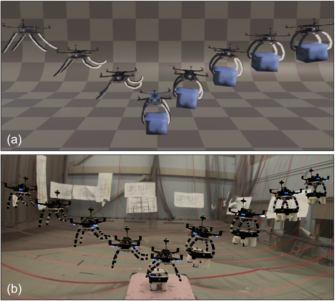
In contrast, biological systems (e.g., birds) rely on compliance and softness to enable the performance and robustness which so differentiate natural from artificial systems [9]. Soft manipulators passively conform to the grasped object, enabling tolerance to imprecisions and reducing the need for explicit grasp analysis; this is an example of morphological computation, the exploitation of passive mechanical elements to supplement explicit control [10]. However, the use of soft grippers in aerial manipulation poses new challenges: the system has infinite degrees of freedom and is no longer differentially flat. Our previous work [11] provides an initial design to overcome these challenges but only demonstrates the resulting system in simulation. In this paper, we take a step further and present the first real prototype of a soft drone, demonstrating its potential in dynamic grasping (Fig. 1). We also make substantial changes to the design of the gripper and adopt an improved control scheme.
Related Work. Compliant aerial manipulation is a growing research area, with several contributions focusing on differentially flat systems with limited degrees of freedom [12]. Cable-slung loads [13, 14, 15] are a well-studied under-actuated payload, where the cable is either treated as massless or reduced to a finite number of links [16]. Thomas et al. [17] carry out dynamic grasping with a rigid under-actuated gripper (see also [18, 19]), but focus on grasping a suspended object — a setup that avoids unplanned contact forces. The AEROARMS project [20, 21] explores the use of a manipulator with a flexible link to minimize disturbance on the aerial platform but adds a passive joint to eliminate the impact of compliance on the drone dynamics. Deng et al. [22] implement and control a soft-bodied multicopter in simulation; their work relies on a gray-box neural network for system identification and does not consider manipulation.
Related work also investigates new quadrotor designs that adjust to different environments. Falanga et al. [1] develop a drone that folds its arms to fit into narrow gaps. Ramon et al. [23] propose soft landing gear (similar in spirit to our design) but do not model or control the soft component beyond a binary open/close, and focus on perching rather than grasping. Mintchev et al. [24] use insect-inspired structural compliance to minimize impact damage.
Our paper connects aerial manipulation with the emerging discipline of soft robotics [10, 25]. Soft robotics research has developed bio-inspired tendon-actuated soft grippers [26, 27, 28], and mathematical models to describe soft robots using finite element methods [29, 9, 30] and piecewise-constant-curvature approximations [31, 32]. These works have not been applied in the context of aerial grasping, where the soft gripper becomes a time-varying payload for a drone and impacts its dynamics.
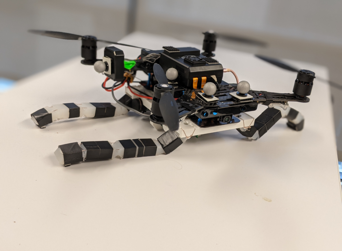
Contribution. This paper presents the first prototype of a soft drone (Fig. 2), a quadrotor platform where traditional landing gear is replaced with a soft tendon-actuated gripper to enable dynamic grasping. Our first contribution is to describe our soft drone prototype (Section II), including electro-mechanical design, software infrastructure, and fabrication. Our system relies on a bio-inspired soft finger design, realized using lightweight tendon-actuated silicone rubber.
Our second contribution (Section III) is to review the algorithms we use for trajectory optimization and control of the drone and the soft gripper. For the drone, we combine a minimum-snap trajectory optimizer [33] with the adaptive geometric controller of Goodarzi et al. [34]. The adaptive controller is instrumental to enable grasping in real tests: it allows the drone to quickly adjust to changes in the quadrotor dynamics due to the swinging soft gripper and the mass of the object being grasped and mitigates other state-dependent aerodynamic disturbances, such as the ground effect [35]. For the soft gripper, we use a feedforward controller applied to the trajectory optimization scheme of [11].
Our last contribution (Section IV) is an extensive evaluation of our system. We evaluate our soft drone in realistic simulations based on SOFA [36] and Unity, and test our prototype in real grasping experiments. In simulation, we compare the proposed platform against a rigid analogue and demonstrate the advantages of our choice of control algorithms and the advantage of softness. In the real tests, we fly our soft drone in a motion-capture room and show that it bears out its theoretical promise and is able to dynamically grasp an object of unknown shape. We release dynamic grasping videos in the supplementary material.
II Soft Drone Design and Prototyping
(a)
(b)
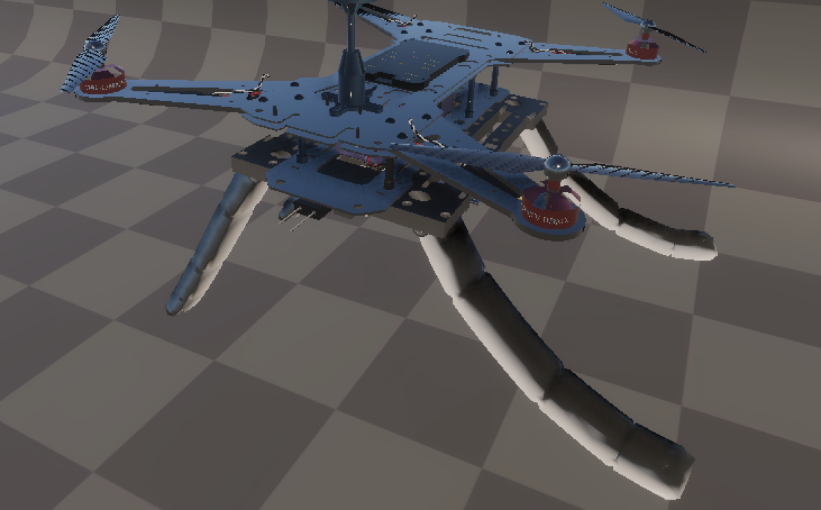
Our soft drone system consists of a standard quadrotor with the (rigid and heavy) landing gear replaced by a soft gripper (Fig. 2). The gripper comprises four silicone rubber fingers attached to the quadrotor base, and placed in a configuration similar to the rigid landing gear they replace; this configuration allows the fingers to achieve force closure in an enveloping grasp and support a stable landing. The gripper is actuated by 16 tendons (similar to the design by Hassan et al. [28]) — two on each side of each finger. However, there are only four unique tendon lengths: tendons on the same side of a finger are coupled to prevent finger twist while those on the same side of each pair of fingers oriented in the same direction are coupled to enforce planarity, simplifying planning [9]. The quadrotor base uses four motors and propellers for actuation as usual. In summary, the system uses 8 control variables: 4 motor speeds for the quadrotor, and 4 tendon lengths (later called the rest lengths) for the gripper. These variables control the 6-dimensional quadrotor pose and the infinite-dimensional state describing the soft gripper configuration.
II-A Quadrotor Base
The quadrotor base of our soft drone is based on the Intel Aero Ready To Fly quadrotor, which is customizable and can be easily interfaced with the Robot Operating System (ROS) and standard motion capture systems (e.g., Optitrack or Vicon), which are used to supplement the quadrotor’s state estimation and relay the location of the target object to grasp. The quadrotor also features a relatively compact combination of an embedded real-time flight controller running the PX4 Autopilot [37] combined with a more capable companion computer (the Intel Aero Compute Board) dedicated to running ROS. This setup allows us to naturally relegate low-level control (running at 250Hz) to the flight controller and execute polynomial trajectory optimization on the onboard computer at 50Hz [11].
II-B Soft Gripper Design and Prototyping
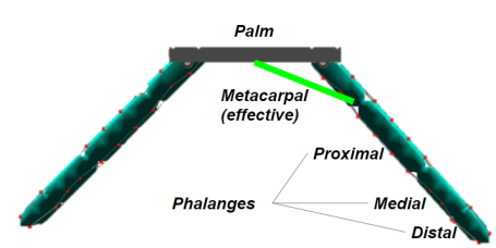
Mechanical Design. Our soft fingers are long and are attached to a -wide base at a 45 degree angle (Fig. 3). The fingers nominally deform continuously, but we add cutouts to the silicone to guide the deformations. The joint placement is inspired by a human finger (a common methodology in robotic hand design [38]): the three joints divide the base and finger into metacarpal, proximal, medial and distal segments (the latter three known collectively as “phalanges”), which are sized in the same approximate 3.5:2.5:1.5:1 ratio as a human finger [39]. Further, we restrict the nominal range of motion of the cutouts to 90, 90, and 30 degrees, similar to a human finger.
Fabrication. We mold our fingers using Smooth-On Dragon Skin 30 silicone rubber. To route tendons through the fingers, low-friction nylon tubing is integrated into the mold and secured with electrical tape (Fig. 2(a)). These components are attached to a 3D-printed base (Dremel Eco-ABS), which mounts directly to the quadrotor. Our tendons are 80lb-test braided fishing line (Power-Pro Super 8 Slick), running through the fingers and base to 3D-printed winches attached to our motors.
Electronics. The gripper is controlled by an Arduino Due microcontroller, which receives tendon length commands from the Intel Aero Compute Board on the quadrotor via USB and issues proportional commands to four motors via two TB6612 Motor Drivers (with motor voltage via a 12V boost/buck regulator) on a custom shield. To control the outer tendons, we used two 298:1 Pololu Micro Metal Gearmotors; for the inner tendons, which are under higher loads, we use two 250:1 Pololu 20D Metal Gearmotors.
III \AggressiveGrasping with a Soft Drone
Our soft drone is tasked with grasping an object of unknown shape, given the coordinates of its centroid. We measure the state of the quadrotor (e.g., from an onboard state estimator or a motion-capture system), but not that of the soft gripper. Let us call the state of the quadrotor base (i.e., a 3D pose and its derivatives) at time , and the infinite-dimensional matrix describing the 3D position of every point of the soft gripper. Call the quadrotor propeller thrust forces at time , and the tendon lengths that actuate the fingers. Below, we omit the dependence on time when possible. Our desired trajectory and control law can be formulated as an optimal control problem:
| (1) |
where is the cost functional that, for instance, penalizes control usage or encourages smooth state changes, the constraint ensures that the solution satisfies the platform dynamics, is the given initial state of the soft aerial manipulator at the initial time , is the desired state at the final time (say, the end of the execution), and is the desired state of the soft gripper at the time of grasp .
Obtaining a control policy by directly solving (1) is impractical even without the soft gripper [40]. The situation is exacerbated in our grasping problem, since (i) our system is not differentially flat due to the soft gripper, (ii) the grasp induces unmodeled contact forces, and (iii) we cannot neglect aerodynamic effects when operating near surfaces. Therefore, we first compute a nominal state trajectory via trajectory optimization [40] and then design a controller to track such a trajectory while rejecting unmodeled disturbances. In particular, we use a minimum-snap polynomial optimization to find the optimal quadrotor trajectory, which informs a finite element model to compute desired tendon lengths at key instants [11]. Then, we apply an adaptive controller to track the quadrotor trajectory, while the tendon lengths are interpolated in open loop. More details are provided below.
III-A Soft Drone Control and Trajectory Optimization
We use the decoupled trajectory optimization approach we proposed in [11] but adopt a more advanced control scheme. Intuitively, we first solve a trajectory optimization problem for the quadrotor to ensure it reaches a feasible grasp pose, and then we solve a trajectory optimization problem for the soft gripper given the quadrotor trajectory.
Quadrotor Trajectory Optimization and Control. We use a polynomial trajectory optimization approach [40, 33] to compute a minimum-snap trajectory that starts at the initial drone position, ends at a desired final position at the terminal time , and passes through an intermediate waypoint a finger-length above the target object at the time of grasp . We denote the nominal drone trajectory resulting from the minimum-snap trajectory optimization as .
Our previous work [11] used a simple geometric controller to track the nominal trajectory in simulation, and the presence of the soft gripper is treated as an unknown disturbance. The experiments in this paper show serious challenges to that approach in real dynamic grasping scenarios. First, after grasping, the mass of the grasped object becomes a constant disturbance which causes a constant offset in the tracking error. More importantly, real problems entail state-dependent aerodynamic disturbances that are not modeled in common simulators. The ground effect, which is the extra lift incurred by a quadrotor moving close to the ground, becomes visible when our drone approaches the surface the target object lies on; if uncompensated it induces a positive offset in the vertical position of the drone, pushing it too far above the target object to grasp. To address these issues, we adopt the adaptive geometric controller of Goodarzi et al. [34], which we review below.
The quadrotor dynamics are modeled as:
| (2) |
where the quadrotor state includes the quadrotor position , rotation , linear velocity , and angular velocity , and we denoted the columns of as ; in (2), is the total mass of the platform and gripper, is the gravity vector, is the moment of inertia, is the scalar thrust force (applied at the quadrotor center of mass and along the local vertical direction ), and are (possibly state-dependent) disturbances induced by our soft gripper.
According to [34], we compute the control actions (i.e., the thrust magnitude and the moment vector) as:
| (3) | |||||
| (4) | |||||
where are the desired position, attitude, and angular velocity, respectively, are the position, velocity, rotation, and angular velocity errors, are estimated disturbances on the translation and rotation dynamics, and are user-specified control gains. In (3), the geometric terms describe a proportional-derivative action (plus extra terms compensating for the desired state) and are the same used in a standard geometric controller [11, 41]. However, the control law (3) also includes adaptive terms that aim at learning the external disturbances .
Assuming bounded disturbance , (where is a given constant), the adaptive terms are adjusted online using the following law:
| (5) |
where are user-specified gains and is a suitable projection function. Eq. (5) estimates the time-varying disturbances to explain residual translation and rotation errors, but projects these estimates to keep them bounded in the ball of radius and avoid their divergence.
Goodarzi et al. [34] prove that this adaptive geometric controller ensures stability and its tracking errors asymptotically go to zero for suitable control gains. In our setup, it enables accurate tracking despite the unmodeled mass of the grasped object and aerodynamic effects (e.g., drag, ground effect).
Soft Gripper Optimization and Control. We compute a nominal trajectory for the gripper given the nominal quadrotor base trajectory, by solving for the desired configuration of the gripper as well as the optimal tendon lengths over time. Details of our approach can be found in [11]. We divide the grasp into two phases: “approach” (opening the gripper as the quadrotor approaches the target location, so as to allow the fingertips to surround the grasped object) and “grasp” (contracting the fingertips to achieve an enveloping grasp).
In particular, we compute the optimal configuration at the approach time (the moment when the leading fingertips are first above the target centroid, which can be determined from the nominal base trajectory ) by solving the following optimization problem:
| (6) |
where is the position of the grasp target and are the fingertip positions of the gripper. The cross product encourages the gripper to open the fingers and results in an asymmetric configuration (Fig. 8) where the fingers nearest to the target are lifted, while those farther envelop the target.
Similarly, we compute the optimal configuration at the given time of grasp by solving the following optimization:
| (7) |
which simply tries to move the fingertips as close as possible to the object centroid.
We remark that the optimization problems (6) and (7) are nontrivial to solve since they involve the continuously-deformable soft state . Our approach follows Bern et al. [29], approximating the infinite-dimensional soft gripper configuration as a set of discrete nodes arranged in a tetrahedral mesh, as in finite element methods (FEM). Tendons are approximated as one-sided springs with (un-stretched) rest lengths which we control directly. A set of pins (also modeled as linear springs) fix the mesh nodes to the quadrotor base, and mass is approximated as concentrated in the nodes. We assume that the soft gripper is quasi-static, i.e., there is an instantaneous relation between rest lengths and gripper configuration .
We iteratively solve for the lengths yielding an optimal configuration . Starting from an initial guess and (the rest configuration in our tests), we analytically compute a descent direction from the Jacobian (details in [11, 29]) and search along it111In practice we use parameters and in computing the Armijo-Goldstein rule [42] in backtracking line search along the gradient, as well as enforcing a step size norm between and . Further, we choose a learning rate of 2.5 when computing the approach lengths and 0.25 when computing the grasp lengths. for a suitable step . Next, we find the new quasi-static configuration associated with the new tendon rest lengths by minimizing the total system energy using Newton’s method.222We use the Newton-CG implementation in scipy.optimize.minimize, with as an initial guess. The process is iterated till convergence, yielding a configuration and tendon lengths which are approximately optimal.
Finally, between the instants for which we explicitly calculate tendon lengths (i.e., and ), we perform a simple linear interpolation between the known lengths we compute above. This is shown to minimize the norm of the time-derivative of the tendon length in [11], hence penalizing rapid changes in tendon lengths (which would result in undesirably large forces on the tendon attachment points).
In summary, we solve explicitly for tendon lengths at times (right before grasping) and (time of grasp) which yield configurations and . We choose to maximize the area between fingertips and the target given the quadrotor pose at that instant (eq. (6)), thus maximizing the chance of an enveloping grasp. We choose to bring the fingertips as close as possible to the target centroid (eq. (7)). Until time we linearly interpolate from initial to “approach” lengths; from to we interpolate from “approach” to “grasp” lengths; after , tendon lengths are held constant; throughout, tendon lengths are applied in open loop.
IV Experiments
We evaluate the effectiveness of our soft drone in photo-realistic simulations and in real tests. Our experiments show that (i) in simulation, the adaptive controller converges regardless of the soft payload and ensures smaller errors compared to a standard geometric controller, (ii) our system reliably achieves aggressive grasps (at up to 2) of objects of unknown shape while a rigid manipulator fails, (iii) in real tests, our soft drone ensures successful grasps in 21 out of 23 consecutive tests, despite unmodeled aerodynamic effects.
IV-A Photo-realistic Physics Simulations
Unity-SOFA Simulation Setup. We simulate our soft drone in Unity, a popular 3D game engine. The underlying physics simulation uses the Unity plugin [SofaUnity] for SOFA [36], a popular open-source soft dynamics simulator with dedicated plugins for tendon-actuated soft manipulators [30].
Unless otherwise noted, we use a simulation and control timestep of 0.01. The rigid frame of the manipulator is modeled after the frame of the Intel Ready to Fly quadrotor (size: ), while the four fingers are modeled as described in Section II (each with size: ). We choose quadrotor mass and inertia and assume aerodynamic drag on the quadrotor center of mass with body drag coefficient . For the soft components, we attempt to replicate the material properties of Smooth-On Dragon Skin 30 in simulation: we use Young’s modulus , Poisson’s ratio , Lamé parameters , [43], and density . The controller gains are set to . Our simulated grasp target weighs 100 grams, approximately the same as our intended real target.
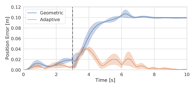
Ablation: Quadrotor Controller. Our first ablation study compares the adaptive controller with a standard geometric controller (Fig. 4). While the original adaptive controller paper already reports a thorough evaluation for general use [34], we specifically compare the two controllers while grasping: we plan grasp trajectories across a range of velocities ( to ) and measure tracking errors. The resulting statistics for the position error are given in Fig. 4 (shaded area shows the 1-sigma deviation of the errors). The adaptive controller has lower error throughout the trajectory, but much better performance after grasping the target; in particular —after grasping— the tracking error of the adaptive controller converges to zero (as predicted by the convergence results in [34]), while the geometric controller exhibits a significant steady state error (around ) caused by the presence of the unmodeled mass of the grasped object.
Ablation: Rigid vs. Soft for Aggressive Grasping. We compare our soft drone against a 2-DOF rigid gripper of identical dimensions with a pre-programmed open-close action executed in open loop. To prevent the simulated gripper from clipping through the target, in these experiments we decrease the simulation timestep to but maintain the 100 control rate.
Fig. 5 reports tracking errors during successful grasp trajectories for the soft and rigid gripper. The soft gripper leads to 50% smaller peak errors compared to its rigid counterpart: the soft gripper passively dampens the contact forces during grasping leading to smaller trajectory perturbations.
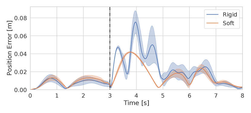
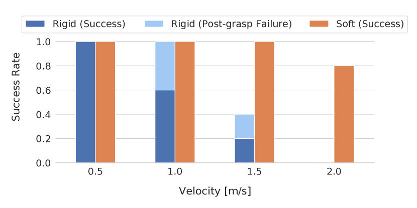
Fig. 6 evaluates the success rate of the soft drone compared to a rigid gripper. We simulated 5 trials of grasping at 4 different desired grasp velocities (, , , ) and recorded the fraction of tests in which the drone remains stable and grasps the object. Our soft drone outperforms its rigid analogue at high velocities, and in particular the success of the rigid gripper drops to 40% (against 100% of the soft) at , and all “rigid” tests fail at . In general, the rigid gripper fails because it either makes an unexpected contact with the target or because the very large contact forces at higher velocities destabilize the controller; the magnitude of the contact forces is further exacerbated by the limitations of the SOFA simulator as discussed below. The soft gripper, on the other hand, absorbs large contact forces and consistently achieves grasping.
Limitations of Soft Simulation. We observed several limitations in our physics simulation setup. As mentioned above, clipping and penetration between objects are common in SOFA at high velocities.
Moreover, rigid-to-rigid contacts exhibit extremely large instantaneous forces despite our attempts to tune the simulator; as a consequence, the high-velocity grasps (in particular when using the rigid gripper) vary in stability with the simulation timestep. This is the reason why we reported the post-grasp failures in Fig. 6 as a separate category. Additionally, our simulator does not model complex aerodynamic effects such as the ground effect.
IV-B Real evaluation
Real testing setup. We evaluate our real system using an Optitrack motion capture system for state estimation, communicating with the Intel Aero drone via ROS. Additionally, we implemented a custom version of PX4 that replaced the original position and attitude controllers with the adaptive controller formulation of [34]. The controller gains for all experiments were set to .333Note that due to how PX4 manages the mapping between desired wrench and motor speeds, we were required to scale components of the wrench by an arbitrary factor. This resulted in the order of magnitude larger attitude gains between the real system and the simulated one. We omit the derivatives of the velocity errors and the second derivative of the adaptive term from the computation of the angular velocity and acceleration since we do not directly estimate jerk and acceleration (and the raw measurements from the IMU are too noisy). We manually calibrate the static translational offset between the drone body frame as estimated by Optitrack and the drone’s center of mass to be . Initial tendon rest lengths are calibrated to be . In the tests, we precomputed tendon lengths offline as in Section III (which requires [11]); all other computation takes place onboard. Our real grasping experiments use a foam target weighing . Our combined quadrotor and gripper weighs , while the maximum load for our quadrotor is . We observe good grasping performance despite the fact that we operate near the maximum payload.
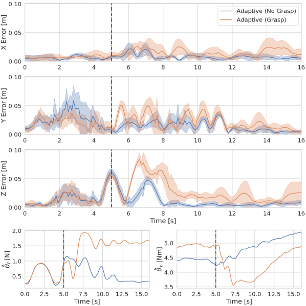
Impact of Unmodeled Aerodynamic Effects. As in simulation, we first evaluate the tracking errors for our system comparing the case where it grasps an object against the case in which it executes the same trajectory without any object to grasp. Fig. 7 reports statistics over 5 runs. In contrast to simulation, our real tests manifest an additional source of error: the “ground effect” —created by the platform our target rests on— pushes the quadrotor upward during grasp. The influence that the ground effect is clearly visible from Fig. 7: while the position errors in the horizontal plane (X,Y) are mostly low before grasping (), the vertical error (Z) rapidly increases right before grasping (), when the drone approaches the surface the object is laid on. Note that the ground effect impacts both case (i.e., grasp or no grasp), while the errors induced by grasping become visible after . The bottom plot in Fig. 7 reports the norm of the adaptive terms and and shows that (i) the term increases before to counteract the ground effect, and (ii) the steady state value of is larger after grasping since it compensates for the mass of the grasped object (similarly compensates for unmodeled torques from the object).
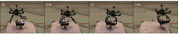
Dynamic Grasping Results. Fig. 8 showcases our real system during dynamic grasping at . The physical restrictions of our first prototype — including thrust saturation, state estimation delays, and soft gripper latency — limit its maximum speed; at the same time it enables us to provide a convincing example of dynamic grasping without the slow, precise positioning required by existing aerial manipulators. The tendon lengths computed by our trajectory optimization were for approach and for grasp (cf. Section III).
| Total Trials | Successes | Velocity at grasp |
|---|---|---|
| 23 | 21 (91.3%) |
Table I reports statistics from 23 real tests (including those in Fig. 7), while several examples are included in the video attachment. The success rate confirms our soft drone can reliably perform dynamic grasping in the face of real-world disturbances. Moreover, our two observed failures were due to catastrophic state estimate divergence (causing the drone to crash instantly) and seem unrelated to grasping; we have observed similar errors in other tests without grasping and without the soft gripper attached. In this case they occurred at the end of the grasp trajectory on the fifth and tenth trial, causing the drone to crash while carrying the grasped object.
The 23 grasping trials took place consecutively across two days and were only interrupted to replace the batteries or reset the system after a crash. Throughout, the soft drone’s performance was essentially unchanged. This consistency was despite adverse positioning errors which often resulted in at least one finger making no contact with the target (and the remaining fingers needing to adapt to compensate) – exemplifying the advantages of morphological computing.
We also attempted 5 grasping trials with the standard geometric controller, and none of them resulted in a grasp (i.e., the drone passed too far above the object). This is due to the fact that the geometric controller has larger tracking errors and is not able to compensate for the ground effect.
Limitations and Discussion. During real testing, we observed several phenomena that were not captured in the simulation of our system and that initially impacted our ability to grasp. Besides the ground effect that caused poor tracking performance for the drone in the vicinity of the object, we also observe a “thrust stealing” effect, where the grasped object would block airflow of the propellers.
To address the ground effect, we also replicated the approach of [44], in which a compensatory force for the ground effect is learned from previous flights around the area of interest. We observed better tracking performance near the ground using this approach, but the learned model did not generalize to the reaction forces that the quadrotor encounters during grasping, leading to large errors after grasping.
Regarding the thrust stealing effect, we observed that keeping the mass of the target object the same while increasing its surface area resulted in the quadrotor not being able to stay in the air when moving between waypoints. We noticed also that more partial grasps led to worse trajectory tracking performance after grasping. While the effects were exaggerated in our system due to how close we were to the maximum takeoff weight of the quadrotor, we believe that the thrust stealing effect will deserve serious consideration in future systems. This is likely due to the fact that this effect —unlike the extra mass and moment the grasped object imparts on the system— cannot be treated as a simple wrench disturbance that can be compensated for.
V Conclusion
This paper presents the first prototype of a soft drone — a quadrotor where rigid landing gears are replaced with a soft tendon-actuated gripper to enable aggressive grasping. We describe our soft drone prototype, including design and fabrication, and review the set of algorithms we use for trajectory optimization and control. We evaluate the resulting system in photo-realistic physics simulations (based on SOFA and Unity) and in real tests in a motion-capture room. Our drone is able to dynamically grasp objects of unknown shape where baseline approaches fail and with a success rate of across 23 trials. Our tests reveal three elements that are key to successful dynamic grasping: (i) the use of an adaptive controller (that can compensate for the disturbances induced by the grasped object and unmodeled aerodynamic effects), (ii) the use of a trajectory optimization scheme to optimize the gripper configuration during grasping, (iii) the role of softness in mitigating the effect of tracking errors, dampening contact forces, and allowing the gripper to better conform to the target object during grasping.
While we demonstrate exciting initial results, pushing the envelop of aggressive grasping to meet the performance observed in nature will require further research on design, algorithms, and fabrication, and provides a formidable challenge for the robotics community. We see two future challenges as potential catalysts for progress in this area: (i) aggressive grasping at speed higher than , and (ii) aggressive grasping on moving platforms without requiring the speed of the drone to match that of the moving platform, a setup that has been described as “unsafe to perform” in conjunction to landing with a traditional quadrotor [45].
References
- [1] D. Falanga, K. Kleber, S. Mintchev, D. Floreano, and D. Scaramuzza, “The foldable drone: A morphing quadrotor that can squeeze and fly,” IEEE Robotics and Automation Letters, 2018.
- [2] K. Bodie, M. Brunner, M. Pantic, S. Walser, P. Pfändler, U. Angst, R. Siegwart, and J. Nieto, “An omnidirectional aerial manipulation platform for contact-based inspection,” Arxiv, 2019. [Online]. Available: https://arxiv.org/pdf/1905.03502.pdf
- [3] G. Loianno and V. Kumar, “Cooperative transportation using small quadrotors using monocular vision and inertial sensing,” IEEE Robotics and Automation Letters, 2018.
- [4] C. Thiels, J. Aho, S. Zietlow, and D. Jenkins, “Use of unmanned aerial vehicles for medical product transport,” Air Medical Journal, 2015.
- [5] J.-P. Ore, S. G. Elbaum, A. J. Burgin, B. Zhao, and C. Detweiler, “Autonomous aerial water sampling,” in Field and Service Robotics, 2013.
- [6] H. Khamseh, F. Janabi-Sharifi, and A. Abdessameud, “Aerial manipulation—a literature survey,” Robotics and Autonomous Systems, 2018.
- [7] J. Dentler, S. Kannan, M. A. O. Mendez, and H. Voos, “A real-time model predictive position control with collision avoidance for commercial low-cost quadrotors,” in 2016 IEEE Conference on Control Applications (CCA), 2016, pp. 519–525.
- [8] R. Rossi, A. Santamaria-Navarro, J. Andrade-Cetto, and P. Rocco, “Trajectory Generation for Unmanned Aerial Manipulators Through Quadratic Programming,” IEEE Robotics and Automation Letters, 2017.
- [9] J. M. Bern, P. Banzet, R. Poranne, and S. Coros, “Trajectory optimization for cable-driven soft robot locomotion,” in Robotics: Science and Systems (RSS), 2019.
- [10] D. Rus and M. T. Tolley, “Design, fabrication and control of soft robots,” Nature, 2015.
- [11] J. Fishman and L. Carlone, “Control and trajectory optimization for soft aerial manipulation,” in IEEE Aerospace Conference, 2021, arXiv preprint arXiv: 2004.04238, .
- [12] B. Yüksel, G. Buondonno, and A. Franchi, “Differential flatness and control of protocentric aerial manipulators with any number of arms and mixed rigid-/elastic-joints,” in IEEE/RSJ Intl. Conf. on Intelligent Robots and Systems (IROS), 2016.
- [13] P. Foehn, D. Falanga, N. Kuppuswamy, R. Tedrake, and D. Scaramuzza, “Fast Trajectory Optimization for Agile Quadrotor Maneuvers with a Cable-Suspended Payload,” in Robotics: Science and Systems (RSS), 2017.
- [14] K. Sreenath, N. Michael, and V. Kumar, “Trajectory generation and control of a quadrotor with a cable-suspended load - A differentially-flat hybrid system,” in IEEE Intl. Conf. on Robotics and Automation (ICRA), 2013, pp. 4888–4895.
- [15] P. Kotaru, G. Wu, and K. Sreenath, “Dynamics and control of a quadrotor with a payload suspended through an elastic cable,” in American Control Conference (ACC), May 2017, pp. 3906–3913.
- [16] F. Goodarzi, D. Lee, and T. Lee, “Geometric stabilization of quadrotor uav with a payload connected by flexible cable,” Proceedings of the American Control Conference, 2014.
- [17] J. Thomas, G. Loianno, J. Polin, K. Sreenath, and V. Kumar, “Toward autonomous avian-inspired grasping for micro aerial vehicles,” Bioinspiration & Biomimetics, 2014.
- [18] P. E. Pounds, D. R. Bersak, and A. M. Dollar, “The Yale Aerial Manipulator: Grasping in flight,” in IEEE Intl. Conf. on Robotics and Automation (ICRA), 2011.
- [19] S. B. Backus, L. U. Odhner, and A. M. Dollar, “Design of hands for aerial manipulation: Actuator number and routing for grasping and perching,” in 2014 IEEE/RSJ International Conference on Intelligent Robots and Systems, 2014.
- [20] A. Caballero, A. Suarez, F. Real, V. Vega, M. Bejar, A. Rodríguez Castano, and A. Ollero, “First experimental results on motion planning for transportation in aerial long-reach manipulators with two arms,” in IEEE/RSJ Intl. Conf. on Intelligent Robots and Systems (IROS), 2018.
- [21] A. Ollero, G. Heredia, A. Franchi, G. Antonelli, K. Kondak, A. Sanfeliu, A. Viguria, J. R. Martinez-de Dios, F. Pierri, J. Cortes, A. Santamaria-Navarro, M. A. Trujillo Soto, R. Balachandran, J. Andrade-Cetto, and A. Rodriguez, “The aeroarms project: Aerial robots with advanced manipulation capabilities for inspection and maintenance,” IEEE Robotics Automation Magazine, vol. 25, no. 4, pp. 12–23, 2018.
- [22] Y. Deng, Y. Zhang, X. He, S. Yang, Y. Tong, M. Zhang, D. DiPietro, and B. Zhu, “Soft multicopter control using neural dynamics identification,” arXiv preprint arXiv:2008.07689, 08 2020.
- [23] P. Ramon, A. E. Gómez Tamm, F. J. Garcia-Rubiales, B. Arrue, and A. Ollero, “Autonomous landing on pipes using soft gripper for inspection and maintenance in outdoor environments,” in IEEE/RSJ Intl. Conf. on Intelligent Robots and Systems (IROS), 2019.
- [24] S. Mintchev, S. de Rivaz, and D. Floreano, “Insect-inspired mechanical resilience for multicopters,” IEEE Robotics and Automation Letters, 2017.
- [25] T. George Thuruthel, Y. Ansari, E. Falotico, and C. Laschi, “Control strategies for soft robotic manipulators: A survey,” Soft Robotics, vol. 5, 2018.
- [26] J. King, D. Bauer, C. Schlagenhauf, K.-H. Chang, D. Moro, N. Pollard, and S. Coros, “Design. fabrication, and evaluation of tendon-driven multi-fingered foam hands,” in 2018 IEEE-RAS 18th International Conference on Humanoid Robots (Humanoids), 2018.
- [27] M. Manti, T. Hassan, G. Passetti, N. D’Elia, C. Laschi, and M. Cianchetti, “A bioinspired soft robotic gripper for adaptable and effective grasping,” Soft Robotics, 2015.
- [28] T. Hassan, M. Manti, G. Passetti, N. d’Elia, M. Cianchetti, and C. Laschi, “Design and development of a bio-inspired, under-actuated soft gripper,” in 2015 37th Annual International Conference of the IEEE Engineering in Medicine and Biology Society (EMBC), 2015.
- [29] J. M. Bern, G. Kumagai, and S. Coros, “Fabrication, modeling, and control of plush robots,” in IEEE/RSJ Intl. Conf. on Intelligent Robots and Systems (IROS), 2017.
- [30] C. Duriez, “Control of elastic soft robots based on real-time finite element method,” in IEEE Intl. Conf. on Robotics and Automation (ICRA), 2013.
- [31] A. D. Marchese, K. Komorowski, C. D. Onal, and D. Rus, “Design and control of a soft and continuously deformable 2d robotic manipulation system,” in IEEE Intl. Conf. on Robotics and Automation (ICRA), 2014.
- [32] A. D. Marchese, R. Tedrake, and D. Rus, “Dynamics and trajectory optimization for a soft spatial fluidic elastomer manipulator,” in IEEE Intl. Conf. on Robotics and Automation (ICRA), 2015.
- [33] D. Mellinger and V. Kumar, “Minimum snap trajectory generation and control for quadrotors,” in IEEE Intl. Conf. on Robotics and Automation (ICRA), 2011, pp. 2520–2525.
- [34] F. Goodarzi, D. Lee, and T. Lee, “Geometric adaptive tracking control of a quadrotor unmanned aerial vehicle on SE(3) for agile maneuvers,” J. Dyn. Sys., Meas., Control., no. 9, 2015.
- [35] D. Del Cont Bernard, M. Giurato, F. Riccardi, and M. Lovera, “Ground effect analysis for a quadrotor platform,” in Advances in Aerospace Guidance, Navigation and Control, 2018, pp. 351–367.
- [36] F. Faure, C. Duriez, H. Delingette, J. Allard, B. Gilles, S. Marchesseau, H. Talbot, H. Courtecuisse, G. Bousquet, I. Peterlík, and S. Cotin, “SOFA: a multi-model framework for interactive physical simulation,” in Soft Tissue Biomechanical Modeling for Computer Assisted Surgery, 2012.
- [37] L. Meier et al., “PX4 Autopilot,” https://px4.io/, 2019.
- [38] C. Schlagenhauf, D. Bauer, K.-H. Chang, J. P. King, D. Moro, S. Coros, and N. Pollard, “Control of Tendon-Driven Soft Foam Robot Hands,” in 2018 IEEE-RAS 18th International Conference on Humanoid Robots (Humanoids), 2018, p. 1—7.
- [39] B. Alexander and V. Kotiuk, “Proportions of hand segments,” International Journal of Morphology, vol. 28, pp. 755–758, 09 2010.
- [40] A. Bry, C. Richter, A. Bachrach, and N. Roy, “Aggressive flight of fixed-wing and quadrotor aircraft in dense indoor environments,” Intl. J. of Robotics Research, vol. 37, no. 7, pp. 969–1002, 2015.
- [41] T. Lee, M. Leok, and N. H. McClamroch, “Geometric tracking control of a quadrotor UAV on SE(3),” in IEEE Conf. on Decision and Control (CDC), 2010, pp. 5420–5425.
- [42] J. Nocedal and S. J. Wright, Numerical Optimization, ser. Springer Series in Operations Research. Springer-Verlag, 1999.
- [43] E. Sifakis and J. Barbic, “FEM Simulation of 3D Deformable Solids: A practitioner’s guide to theory, discretization and model reduction,” in SIGGRAPH, 2012.
- [44] G. Shi, X. Shi, M. O’Connell, R. Yu, K. Azizzadenesheli, A. Anandkumar, Y. Yue, and S.-J. Chung, “Neural lander: Stable drone landing control using learned dynamics,” in 2019 International Conference on Robotics and Automation (ICRA). IEEE, 2019, pp. 9784–9790.
- [45] M. Alkowatly, V. Becerra, and W. Holderbaum, “Bioinspired autonomous visual vertical control of a quadrotor unmanned aerial vehicle,” Journal of Guidance, Control, and Dynamics, vol. 38, pp. 249–262, 02 2015.