Giant Inverse Rashba-Edelstein Effect: Application to Monolayer OsBi2
Abstract
We propose that the hybridization between two sets of Rashba bands can lead to an unconventional topology where the two Fermi circles from different bands own in-plane helical spin textures with the same chiralities, and possess group velocities with the same directions. Under the weak spin injection, the two Fermi circles both give the positive contributions to the spin-to-charge conversion and thus induce the giant inverse Rashba-Edelstein Effect with large conversion efficiency, which is very different from the conventional Rashba-Edelstein Effect. More importantly, through the first-principles calculations, we predict that monolayer OsBi2 could be a good candidate to realize the giant inverse Rashba-Edelstein Effect. Our studies not only demonstrate a new mechanism to achieve highly efficient spin-to-charge conversion in spintronics, but also provide a promising material to realize it.
The control and manipulation of the spin-charge interconversion plays a critical role in modern spintronics PRM-spin-hall ; spintronics-2004 . In the two-dimensional system, the (inverse) Edelstein effect has gained much attention since its potential application in spintronics devicesEdelstein-1989 ; PRL-2007-metal ; NC-2013-metal ; APL-2015-metal1 ; APL-2015-metal2 ; PRB-2016-metal3 ; PRB-2016-metal4 ; PRL-2015-metal ; PRL-metal-2016 ; Edelstein-1 ; Edelstein-2 ; NM-1 ; PRL-Sn-2016 . In the direction of inverse Edelstein effect (IEE), a pure spin current through the system generates a transverse charge current , and the Edelstein effect (EE) describes the inverse process. In both cases, the conversion efficiency is defined by , which largely measures the merits of a physical system.
The microscopic mechanism of both EE and IEE requires the presence of the spin-orbit coupling (SOC), which results in the specific spin-momentum locked electronic band structures. Thus, the usual candidate physical systems include the metallic heterostructurePRL-2007-metal ; NC-2013-metal ; APL-2015-metal1 ; APL-2015-metal2 ; PRB-2016-metal3 ; PRB-2016-metal4 ; PRL-2015-metal ; PRL-metal-2016 and the topological insulatorsPRL-2007-TI ; PRB-2007-TI ; RMP-2010-TI ; RMP-2011-TI ; PRL-Sn-2016 ; PRB-TI-2017 ; IEE-TI-2018 . In the metallic heterostructure, the spacial inversion asymmetry lifts the spin degeneracy and gives rise to the Rashba SOCRashba . However, the opposite spin textures of the two lifted bands give the partial compensation of the contributions to the spin-to-charge conversion and suppresses the efficiency PRL-Sn-2016 , and searching for materials with strong Rashba SOC coupling becomes an alternative way to increase in this situationNM-2011-SOC ; Giant-Rashba1 ; Giant-Rashba2 ; Giant-Rashba3 ; Giant-Rashba4 ; Micro-theory ; PRB-theoretical-aspect . Furthermore, the interfacial effects complicate the descriptions of the electronic states beyond the standard Rashba model and limit the application of the metallic heterostructure. In the topological insulator, the topological surface state possesses the single Dirac cone structure, which can get rid of of partial compensation effect in Rashba systemPRL-Sn-2016 . However, the concurrence of surface and bulk states and quantum confinement effect always complicate TI-based systems beyond the controllabilityQuan-confin-1 .
In this work, we propose the third kinds of system, which hosts a new mechanism to achieve the giant IEE with large . The new system has two spin-lifted bands with the identical spin textures, i.e., unconventional Rashba bands, which is very different from the conventional Rashba bands with opposite spin textures. We first construct a simple and generic model to describe such unconventional Rashba bands. We show that it can induce strongly enhanced spin-to-charge conversion and possess the giant IEE with large according to the semi-classical Boltzmann transport theory. The calculated spin-to-charge conversion efficiency is estimated to be ten times that of the conventional Rashba system. More importantly, our first-principles calculations predict a simple compound of monolayer OsBi2 has such unconventional Rashba band structure. The pure bulk states of a single material can overcome the shortcomings of the complexity and sensitivity of the interfacial and surface states in the metallic heterostructure and topological insulators, respectively. These properties make monolayer OsBi2 to be a promising material to realize the giant IEE and to have potential application in spintronics.
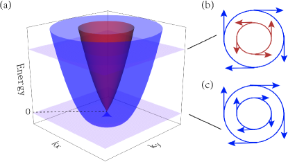
We start with the conventional Rashba bands described by with and the constant and Rashba SOC parameters, respectively. The two outer and inner bands and the Fermi contour involving two Fermi circles for a specific Fermi energy are shown in Fig. 1. The spin textures of the two Fermi circles are denoted by the red and blue arrows, as shown in Fig. 1 (b) and (c). In the case of Fermi energy , the two Fermi circles have spin textures with opposite chiralities and group velocities with the same directions, as shown in Fig. 1 (b). For , the two Fermi circles are from the same outer band , and they have the spin textures with same chiralities but group velocities with opposite directions, as shown in Fig. 1 (c). When the spin current is injected, the opposite chiral spin textures in the former case and the opposite directions of the velocities in the latter case can suppress the converted charge current, because the two Fermi circles give a partial compensation of the contributions to the converted charge currentPRL-Sn-2016 . This is the key reason to limit the spin-to-charge conversion efficiency in Rashba system. To break the bottleneck, a natural strategy is to force both Fermi circles to have positive contributions to spin-to-charge conversion. Namely, both Fermi circles have spin textures with the same chiralities and the group velocities with the same directions. Such unconventional Rashba band structure was experimentally observed in some surface alloy systems such as Bi/Cu(111), and was argued to originate from the hybridizations between different bands and orbitalsPRB-unconventional ; PRB-BiTeI ; kptheory-2019 ; Hy-twobands-2012 .
Inspired by these experimental observations, we consider two sets of Rashba bands with couplings, under the basis []T, the Hamiltonian can be expressed as
| (1) |
where is the electron annihilation operator with , and labeling the orbital, momentum and spin indexes, respectively. describes two sets of independent Rashba bands and has the form
| (2) |
Here, () and () are the parameters for the two sets of Rashba bands, respectively, . describes the spin-flip inter-band couplings and can be parameterized as
| (3) |
Here we keep the terms of to first order because higher-order terms do not change the in-plane spin textures but only induces warping effect (see Sec. III in Supplementary Materials (SMs) for details). The explicit form of is restricted by the symmetry of the physical system we concern. We consider a C3v point group which is exactly possessed by Bi/Cu(111), Pb/Si(111), PbBiI and our predicted monolayer OsBi2. Combined with time-reversal (TR) symmetry, should satisfy
| (4) |
and
| (5) |
where is the symmetry operation of point group, is the matrix representation of , and is TR operator. For C3v point group, there are two group generators which are rotating around -axis and reflecting by the three vertical mirrors. Applying these restrictions on , we obtain , where is a real parameter (See Sec. V in SMs for details).
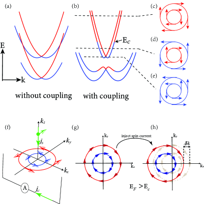
The band structures from of Eq. (1) depend on the values of () relative to (). Here, we focus on the case with ()=(), which is also the situation owned by monolayer OsBi2. The discussions of other cases are shown in Sec. I in SMs. Assume all the constant parameters are positive, can be solved analytically. The band structures are shown in Fig. 2. Consider a couple of inner and outer Fermi circles from the two higher-energy bands as shown in Fig. 2(b), the spin textures can be evaluated by . , with and spanning the orbital and spin space. Then,
| (6) | ||||
| (7) |
according to which, three regions can be divided by different fillings. Region I is from to zero, where the two Fermi circles is from the single outer band and have the same chiral spin textures, as shown in Fig. 2(e). Region II is from zero to with and . In region II, the two Fermi circles possess opposite chiral spin textures, as shown in in Fig. 2(d). Region III is from to infinity, where the two Fermi circles share the same chiral spin textures, as shown in in Fig. 2(c). More remarkably, two Fermi circles in Region III have the same directions of velocities. This means the band structures in the Region III belong to the unconventional Rashba-type. The situations are similar for the two lower-energy bands in Fig. 2 (b).
Now, we consider the spin injection process as shown in Fig. 2 (f). In Region III, the two Fermi circles should move along the same direction in momentum space, as shown in Fig. 2 (g) and (h). Such Fermi circles shift means the in-plane charge current is generated. This is the physical picture of the spin-to-charge conversion, i.e., the IEE. In the semiclassical Boltzmann transport theory semiclassical , the shift of the Fermi circles is equivalent to application of a homogeneous electrostatic field , which generates a directional current and makes the distribution function to deviate from the equilibrium distribution function . In the zero-temperature limit, we have , and the spin polarization can be expressed as . Here, is the elementary charge, and is the mean free path. Under the relaxation-time approximation, with and the momentum relaxation time and the group velocity, respectively. We consider two Fermi circles from two higher-energy bands, as shown in Fig. 2. (b). Note that the results for two Fermi circles from two lower-energy bands are similar. With the help of the spin textures in Eqs. (6) and (7)(See Sec. II in SMs for details), we have
| (8) |
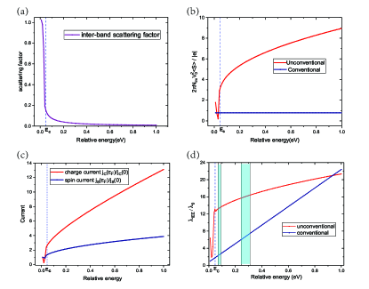
Here, labels the inner and outer Fermi circles, respectively. is the factor for spin polarization. and is the area of the unit cell, the unit vector of group velocity and Fermi momentum, respectively. Since the two Fermi circles share identical directions of spin polarization and group velocity in Region III, they both give positive contributions to total spin polarization. Additionally, as shown in Fig. 3(a), the rate of inter-band scattering is greatly reduced with the increase of , because the spin-flip backscattering is forbidden. Accordingly, the momentum relaxation time is also increased. These two aspects strongly enhance the spin polarization , as shown in Fig. 3(b). When , the factor of spin polarization and radii of two Fermi circles tend to be equal, the spin polarization can be approximately expressed as
| (9) |
with . Here, and denote the number of -scattering centers and the s-wave scattering potential, respectively. In conventional Rashba system, the spin polarization (See Sec. II in SMs for details), which is a constant when . Thus, the spin polarization in unconventional Rashba system rapidly surpasses the conventional one, as shown in Fig. 3(b).
The spin current density shown in Fig. 3 (c) can be related with the spin polarization shown in Eq. (8) by . The generated charge current density shown in Fig. 3 (c) can be obtained by . The spin-to-charge conversion efficiency can be further expressed as
| (10) |
For the conventional Rashba system, with a nearly constant . Then, tends to be the constant , when , and is linearly increased with the shift of , indicated by the blue line in Fig. 3(d). For the unconventional Rashba system, however, with the increase of , the inter-band scattering rate rapidly decreases, as shown in Fig. 3(a), which gives a large momentum-relaxation time . Thus, the larger charge current is generated. Meanwhile, stronger spin polarization generates larger spin current . These two effects compete with each other. The numerical results of the relative and for the unconventional Rashba system are shown in Fig. 3(c), from which, one can clearly find the competitive relation between and . Compared with conventional Rashba system, unconventional Rashba system has lower rate of increase but much larger initial value of length, as indicated by the red curve in Fig. 3(d). In the energy window we most concern, such as the shadowed regions in Fig. 3(d), which correspond to the situations in monolayer OsBi2 with . The unconventional Rashba system has remarkable advantages than conventional Rashba systems.
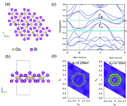
The search for a simple physical material with the unconventional Rashba band structures is of fundamental importance for achieving the giant IEE. Our previous studies indicate the trigonal layered PtBi2-type materials tend to form the buckled structure for the top layer of Bi bulk-PtBi2 . Such kinds of distortion naturally breaks the inversion symmetry. Following the similar strategy, we perform the first-principles calculations to search for the same structures with different elements (See Sec. IV in SMs for details). We find that the monolayer OsBi2 meets all the requirements. The relaxed structure is shown in Fig. 4(a) and (b). The crystal constant is Å. The calculated band structure is shown in Fig. 4(c). The point group is C3v as our aforementioned discussions. With SOC, all the bands at point can be classified into three Irreducible representations (IRs), , and group . Deviate from point, the two sets of the twofold degenerate bands splits into Rashba-type and couple together to give the unconventional spin textures, as conformed by Fig. 4 (d) and (e). The details of the construction of the effective kp model near point are present in Sec. V in SMs.
Note that the aforementioned discussions focus on either the two higher-energy bands or the two lower-energy bands, as shown in Fig. 2(b). In continuous model described by Eq.(1), all the four bands should be considered. However, in monolayer OsBi2, the lattice symmetries force only two bands to be occupied and the other two bands to be gapped when the Fermi energy lies in the shadowed regions, as shown in Fig. 4 (c). This is a crucial point to guarantee the aforementioned results can be applied in monolayer OsBi2. With the fitting parameters from monolayer OsBi2, the of OsBi2 in the shadowed regions indeed realize the giant IEE with , as indicated in Fig. 3 (d). The Fermi level of the pristine monolayer OsBi2 does not lie in the shadowed region in Fig. 4(b). To tune it, many practical methods can be adopted, such as chemical doping, electrostatic gating and ionic liquid gating etcGate-1 ; Gate-2 ; Gate-3 ; Gate-4 ; Gate-5 ; Gate-6 ; Gate-7 .
In conclusion, we propose that the unconventional Rashba system can give rise to a new mechanism to realize the spin-to-charge conversion. With the help of semiclassical transport theoretical analysis, we find that the spin-to-charge conversion efficiency is much higher than that in the conventional Rashba system. More meaningfully, our first-principles calculations prove that monolayer OsBi2 belongs to such unconventional Rashba system. It makes monolayer OsBi2 to be a promising material to host the giant IEE. Our studies provide a new mechanism to promote the charge-to-spin conversion efficiency in modern spintronics.
Acknowledgements.
This work was financially supported by the National Key R&D Program of China No. 2017YFA0303201, National Natural Science Foundation of China under Grants (No. 12022413, No. 11674331, No.11625415), the “Strategic Priority Research Program (B)” of the Chinese Academy of Sciences, Grant No. XDB33030100, the ‘100 Talents Project’ of the Chinese Academy of Sciences, the Collaborative Innovation Program of Hefei Science Center, CAS (Grants No. 2020HSC-CIP002), the CASHIPS Director’s Fund (BJPY2019B03), the Science Challenge Project under Grant No. TZ2016001. A portion of this work was supported by the High Magnetic Field Laboratory of Anhui Province, China.References
- (1) J. Sinova, Sergio O. Valenzuela, J. Wunderlich, C. H. Back, and T. Jungwirth, Rev. Mod. Phys. 87, 1213 (2015).
- (2) I. Žutić, J. Fabian, and S. Das Sarma, Rev. Mod. Phys. 76, 323 (2004).
- (3) V. M. Edelstein, Solid State Commun. 73, 233 (1990).
- (4) C. R. Ast, J. Henk, A. Ernst, L. Moreschini, M. C. Falub, D. Pacilé P. Bruno, K. Kern, and M. Grioni, Phys. Rev. Lett. 98, 186807 (2007).
- (5) J. C. Rojas-Sanchez, L. Vila, G. Desfonds, S. Gambarelli, J. P. Attane, J. M. D. Teresa, C. Magen, and A. Fert, Nat. Commun. 4, 2944 (2013).
- (6) S. Sangiao, J. M. D. Teresa, L. Morellon, I. Lucas, M. C. Martinez-Valarte, and M. Viret, Appl. Phys. Lett. 106, 172403 (2015)
- (7) A. Nomura, T. Tashiro, H. Nakayama, and K. Ando, Appl. Phys. Lett. 106, 212403 (2015).
- (8) M. B. Jungfleisch, W. Zhang, J. Sklenar, W. Jiang, J. E. Pearson, J. B. Ketterson, and A. Hoffmann, Phys. Rev. B 93, 224419 (2016).
- (9) M. Isasa, M. C. Martínez-Valarte, E. Villamor, C. Magén, L. Morellón, J. M. De Teresa, M. R. Ibarra, G. Vignale, E. V. Chulkov, E. E. Krasovskii, L. E. Hueso, and F. Casanova, Phys. Rev. B 93, 014420 (2016).
- (10) H. J. Zhang, S. Yamamoto, B. Gu, H. Li, M. Maekawa, Y. Fukaya, and A. Kawasuso, Phys. Rev. Lett. 114, 166602 (2015)
- (11) H. Nakayama, Y. Kanno, H. An, T. Tashiro, S. Haku, A. Nomura, and K. Ando, Phys. Rev. Lett 117, 116602 (2016).
- (12) M. Offidani, M. Milletar, R. Raimondi, and A. Ferreira, Phys. Rev. Lett 119, 196801 (2017).
- (13) L. A. Beníez, W. S. Torres, J. F. Sierra, M. Timmermans, J. H. Garcia, S. Roche, M. V. Costache and S. O. Valenzuela, Nat. Mater. 19, 170-175 (2020).
- (14) E. Lesne, Y. Fu, S. Oyarzun, J. C. Rojas-Sánchez, D. C. Vaz, H. Naganuma, G. Sicoli, J.-P. Attané M. Jamet, E. Jacquet, J.-M. George, A. Barthélémy, H. Jaffrès, A. Fert, M. Bibes and L. Vila, Nat. Mater. 15, 1261-1266 (2016).
- (15) J.-C. Rojas-Sanchez, S. Oyarzún, Y. Fu, A. Marty, C. Vergnaud, S. Gambarelli, L. Vila, M. Jamet, Y. Ohtsubo, A. Taleb-Ibrahimi, P. Le Fèvre, F. Bertran, N. Reyren, J.-M. George, and A. Fert, Phys. Rev. Lett 116, 096602 (2016).
- (16) L. Fu, C. L. Kane, and E. J. Mele, Phys. Rev. Lett. 98, 106803 (2007).
- (17) L. Fu and C. L. Kane Phys. Rev. B 76, 045302 (2007).
- (18) M. Z. Hasan and C. L. Kane, Rev. Mod. Phys. 82, 3045 (2010).
- (19) X.-L. Qi and S.-C. Zhang, Rev. Mod. Phys. 83, 1057 (2011).
- (20) M. Rodriguez-Vega, G. Schwiete, J. Sinova, and E. Rossi, Phys. Rev. B 96, 235419 (2017).
- (21) R. Dey, N. Prasad, L. F. Register, and S. K. Banerjee, Phys. Rev. B 97, 174406 (2018).
- (22) Y. A. Bychkov and E. I. Rashba, J. Phys. C 17, 6039 (1984).
- (23) K. Ishizaka, M. S. Bahramy, H. Murakawa, M. Sakano, T. Shimojima, T. Sonobe, K. Koizumi, S. Shin, H. Miyahara, A. Kimura, K. Miyamoto, T. Okuda, H. Namatame, M. Taniguchi, R. Arita, N. Nagaosa, K. Kobayashi, Y. Murakami, R. Kumai, Y. Kaneko, Y. Onose and Y. Tokura, Nat. Mater. 10, 521-526 (2011).
- (24) J. Park, S. W. Jung, M.-C. Jung, H. Yamane, N. Kosugi, and H. W. Yeom, Phys. Rev. Lett 110, 036801 (2013).
- (25) A. Varykhalov, D. Marchenko, M. R. Scholz, E. D. L. Rienks, T. K. Kim, G. Bihlmayer, J. Sánchez-Barriga, and O. Rader, Phys. Rev. Lett 108, 066804 (2012).
- (26) D. Niesner, M. Wilhelm, I. Levchuk, A. Osvet, S. Shrestha, M. Batentschuk, C. Brabec, and T. Fauster, Phys. Rev. Lett 117, 126401 (2016).
- (27) A. Crepaldi, L. Moreschini, G. Autes, C. Tournier-Colletta, S. Moser, N. Virk, H. Berger, Ph. Bugnon, Y. J. Chang, K. Kern, A. Bostwick, E. Rotenberg, O. V. Yazyev, and M. Grioni, Phys. Rev. Lett 109, 096803 (2012).
- (28) Ka Shen, G. Vignale, and R. Raimondi, Phys. Rev. Lett. 112, 096601 (2014).
- (29) A. Johansson, J. Henk, and I. Mertig, Phys. Rev. B 93, 195440 (2016).
- (30) M. S. Bahramy, P. D .C. King, A. de la Torre, J. Chang, M. Shi, L. Patthey, G. Balakrishnan, Ph. Hofmann, R. Arita, N. Nagaosa and F. Baumberger. Nat. Commun. 3, 1159 (2012).
- (31) H. Mirhosseini, J. Henk, A. Ernst, S. Ostanin, C.-T. Chiang, P. Yu, A. Winkelmann, and J. Kirschner, Phys. Rev. B 79, 245428 (2009).
- (32) C. Mera Acosta, O. Babilonia, L. Abdalla, and A. Fazzio, Phys. Rev. B 94, 041302 (2016).
- (33) I. A. Nechaev and E. E. Krasovskii, Phys. Rev. B 100, 115432 (2019).
- (34) H. Bentmann, S. Abdelouahed, M. Mulazzi, J. Henk, and F. Reinert, Phys. Rev. Lett 108, 196801 (2012).
- (35) I. Mertig, Rep. Prog. Phys. 62, 237 (1999).
- (36) W. Gao, X. Zhu, F. Zheng, M. Wu, J. Zhang, C. Xi, P. Zhang, Y. Zhang, N. Hao, W. Ning M. Tian, Nat. Commun. 9, 3249 (2018).
- (37) G. F. Koster, Properties of the Thirty-Two Point Groups (MIT Press, Cambridge, MA, 1963), Vol. 24.
- (38) L. J. Li, E. C. T. O’Farrell K. P. Loh G. Eda, B. Özyilmaz and A. H. Castro Neto, Nature 529, 185–189 (2016).
- (39) Y. Saito, T. Nojima, Y. Iwasa, Supercond. Sci. Technol. 29, 093001 (2016).
- (40) K. Ueno, S. Nakamura, H. Shimotani, A. Ohtomo, N. Kimura, T. Nojima, H. Aoki, Y. Iwasa, M. Kawasaki, Nat. Mater. 7, 855–858 (2008).
- (41) J. M. Lu, O. Zheliuk, I. Leermakers, N. F. Q. Yuan, U. Zeitler, K. T. Law, J. T. Ye, Science 350, 1353–1357 (2015).
- (42) D. Costanzo, S. Jo, H. Berger, Nat. Nanotechnol. 11, 339–344 (2016).
- (43) E. Sajadi, T. Palomaki, Z. Fei, W. Zhao, P. Bement, C. Olsen, S. Luescher, X. D. Xu, J. A. Folk, and D. H. Cobden, Science 362, 922 (2018).
- (44) V. Fatemi, S. F. Wu, Y. Cao, L. Bretheau, Q. D. Gibson, K. Watanabe, T. Taniguchi, T. J. Cava, and P. Jarillo-Herrero, Science 362, 926 (2018).