Dc Electrical Current Generated by Upstream Neutral Modes
Abstract
Quantum Hall phases are gapped in the bulk but support chiral edge modes, both charged and neutral. Here we consider a circuit where the path from the source of electric current to the drain necessarily passes through a segment consisting solely of neutral modes. We find that upon biasing the source, a dc electric current is detected at the drain, provided there is backscattering between counter-propagating modes under the contacts placed in certain locations. Thus, neutral modes carry information that can be used to nonlocally reconstruct a dc charge current. Our protocol can be used to detect any neutral mode that counterpropagates with respect to all charge modes. Our protocol applies not only to the edge modes of a quantum Hall system, but also to systems that have neutral modes of non-quantum Hall origin. We conclude with a possible experimental realization of this phenomenon.
I Introduction
The quantum Hall effects (QHE) Klitzing et al. (1980) are the earliest known example of topological insulators Hasan and Kane (2010). They have a charge gap in the bulk, and all currents are carried by edge/surface modes, which can be either charged (with fractional charge in the fractional QHE) or neutral chiral modes. While the charge modes produce quantized electrical conductance, neutral modes are a manifestation of topology, electron-electron interactions, and possibly disorder, and contribute to heat transport. Neutral edge modes in quantum Hall systems have been detected by shot noise experiments Bid et al. (2010) and also by their quantized heat transport coefficients Venkatachalam et al. (2012); Deviatov et al. (2011). Apart from quantum Hall systems, neutral (e.g. Goldstone) modes arise in systems in which a continuous symmetry is broken spontaneously.
In this work, we design a geometry where the unique current path from the source to the drain is forced to pass through a segment consisting of neutral modes only. We assume that the symmetry of each channel is broken by the contacts; thus backscattering between channels is present under them. The breaking of these symmetries results in a non-zero dc current at the drain D. This protocol can be used either as a transformer, which converts charge current to neutral current, and then back to charge current, or as an efficient detector of neutral modes as long as the neutral counterpropagates with respect to all charge modes.
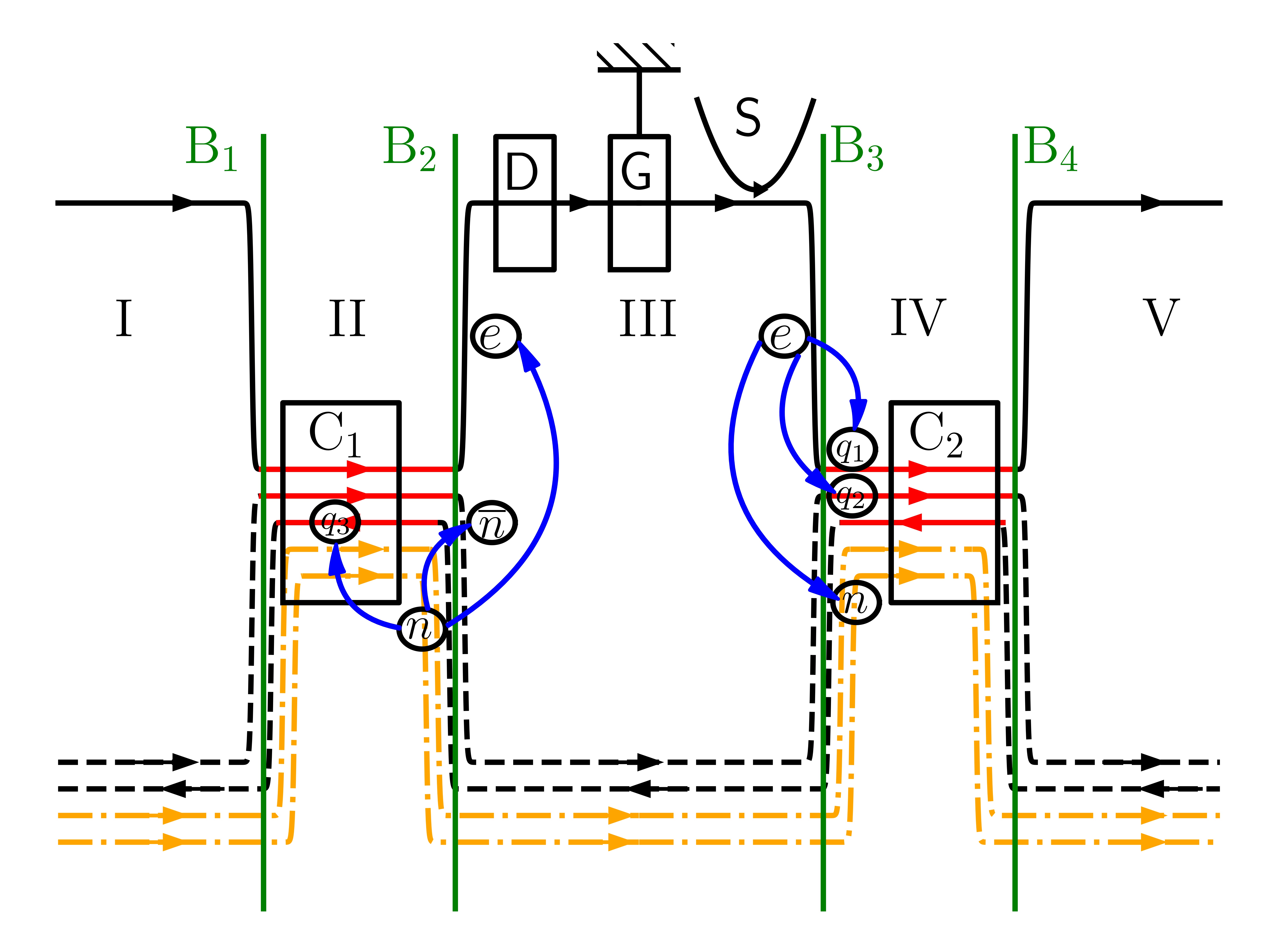
The proposed geometry is shown in Fig. 1. The relevant physics can be extracted by focusing on regions II, III, and IV. The solid black line at the top is a right-moving chiral charge mode, arising from a quantum Hall system extending above Fig. 1, constituting the “probe” system. The dashed lines at the bottom in region III are a pair of counter-propagating gapless, bosonic bos , neutral modes, presumed to arise from a “test” system extending below Fig. 1. The test system may be quantum Hall, so long as all its charge modes (dash-dotted orange lines) are right-moving, or it may be a system with neutral modes only, such as an chain. Electrons are injected from the source S via tunnelling into the probe chiral edge mode and detected at the drain D. The source and drain are separated by a grounded contact G. Clearly, current cannot flow from S to D along the right-moving, chiral top edge. The edge modes of the probe and test systems overlap, and thus interact, only in regions II and IV. The interaction is of the density-density form, with separate number conservation in the “bare” charged and neutral modes. These interactions renormalize the bare charged and neutral modes such that, generically, all three renormalized eigenmodes have nonuniversal charge. Regions II and IV also host the contacts C1 and C2 respectively Spånslätt et al. (2021), which we assume can be decoupled from the interacting modes at will. Finally, regions I and V are semi-infinite “free” regions, where the edges of the probe and test systems are fully decoupled and are present to fix the asymptotic boundary conditions.
Before proceeding we discuss the notion of ideal contacts. The latter refers to terminals connected to the edge modes, which absorb the entire impinging current with no detectable signal away from the contact Kane and Fisher (1995). Ideal contacts have been discussed in Refs. Slobodeniuk et al., 2013; Protopopov et al., 2017; Nosiglia et al., 2018; Spånslätt et al., 2021 in the absence of interactions, and, in the presence of interactions, in Spånslätt et al., 2021, where it was shown that a microscopic realization of an ideal contact for counterpropagating edge modes requires backscattering between them.
Our results can be encapsulated in two ways: Firstly, neutral modes can carry information about the charge current, information that can be used to reconstruct the charge current at a different location. Secondly, one can use the charge chiral mode (top mode of Fig. 1) as a “probe”, and apply it to a “test” system (bottom of Fig. 1). In this functionality, our device can be used to detect coherently propagating bosonic bos neutral modes in the test system. A dc charge current at the drain is direct evidence for neutral modes.
More concretely, let us assume there is at least one left-moving neutral mode in the test system. When electrons are injected at the source S if both C1 and C2 are coupled to the modes in region II and IV respectively, a dc current will be detected at D, regardless of whether the test system has (right-moving) charge chirals or not. The presence of right moving chiral charge modes in the test system will not change this conclusion qualitatively.
Let us understand the physics in two extreme limits, when (i) both the contacts are coupled, or (ii) both of the contacts are decoupled.
Case (i) Both contacts coupled: Assuming no charge chiral modes in the test system, consider a charge (positive by fiat) injected into the probe chiral at S, which travels to the boundary B3. There, a lump of positive neutral density (a neutralon) is reflected into the left-moving neutral mode in region III and lumps of nonuniversal charge are transmitted into the two right-moving modes in region IV to be fully absorbed at C2. The left-moving neutralon in III travels to B2, at which point a positive (electrically) charged lump is reflected into the probe chiral, and an equal and opposite charge is transmitted into the left-moving mode in the region II, to be fully absorbed at C1. There will also be a neutralon reflected into the right-moving neutral chiral in region III, which travels to B3. As usual, this will undergo transmission and reflection, with the transmitted part being completely absorbed at C2. The reflected neutralon part has the same sign as the original neutralon, and repeats the process described earlier with a smaller amplitude. With both contacts coupled, an infinite sequence of charge lumps of the same sign is detected at D. Thus, a dc current at S implies a dc current of the same sign (but with a nonuniversal magnitude) at D.
This is already an instance of the effect we are looking for. Now we add (right-moving) charge chirals to the test system. All proceeds as before until the left-moving neutralon impinges on B2. Now, in addition to the reflected neutral lump, charge lumps will be transmitted into the nonuniversal charge modes in region II (to be absorbed at C1), and reflected into the probe and test charge chirals. The magnitude and sign of the charges are determined by the interaction parameters in region II. Recall that the reflection/transmission is deterministic because no tunneling between the different modes is involved. Thus, there is a dc current at D.
To summarize, when both contacts are coupled, if a left-moving neutral is present in the test system, there is always a dc current at D, as long as the charge chirals (if any) of the test system are all right-moving.
Case (ii) Both contacts decoupled: Initially, let us assume that no charge chiral modes are present in the test system. The first step (the injected lump of electric charge traveling from S to B3, resulting in the reflection of a neutralon and transmission of lumps of nonuniveral charge in the two right-moving chirals in region IV) is the same as before. However, now the right-moving lumps in region IV travel to B4 and undergo repeated partial reflection and transmission. Similarly, the left-moving neutralon, upon arriving at B2, results in a charge lump in the probe charge chiral in III, and a left-moving charge lump in region II. This latter lump will undergo partial transmission/reflection at B1. This leads to multiple scattering at all the boundaries. However, we can assert, based on charge conservation, that no dc current is observed at D. Since no left-moving charge modes enter region III, the entire charge injected at has to proceed to region V (after multiple scattering in region IV) Safi and Schulz (1995); *Maslov_Stone_1995; *Ponomarenko_1995; *Oreg_Finkelstein_1996. Any charge detected at D is initiated by a neutralon arriving at B2 via the left-moving neutral in III and its descendants via multiple scattering. Since no total (time-integrated) charge enters region III from either of regions II or IV, the time-integrated charge entering the drain D must vanish. Evidently, charge noise will be detected at D. Similar logic ensures that the dc charge current exiting region IV into region V is the entire charge current injected at S.
These conclusions do not change when we allow (right-moving) charge modes in the test system. Since the interactions in regions II and region IV are density-density interactions, the total “charge” (which is completely independent of electric charge) of each mode has to be conserved in the dc limit. Thus, we conclude, that in the presence of (right-moving) charge chiral modes in the test system, we still need both the contacts to be coupled in order to have a non-zero current at the drain D.
In what follows, we will present an outline of the calculations leading to our results, relegating straightforward mathematical details to the supplemental material (SM SM ). For simplicity, we will focus on the case where the test system has neutral modes only.
We model the neutrals by an XXZ spin chain and the interaction between the spin chain and the spin-polarized charged mode as a spin-spin interaction. The model is described by the action in Eq. 1 where the probe charged mode is represented by the bosonic field , the right-moving test neutral by and the left-moving test neutral by . The interaction between the neutrals and is denoted by . The interaction between the charged mode and the spin chain, (the same for both the left- and right-moving neutrals), is denoted by (= )
| (1) |
Assuming the interactions are turned on abruptly in regions II and IV, we calculate the reflection () and transmission coefficients () at B2 and B3, which allows us to compute the current at D as a function of time via multiple reflections Safi and Schulz (1995); *Maslov_Stone_1995; *Ponomarenko_1995; *Oreg_Finkelstein_1996.
II Computation of current and noise
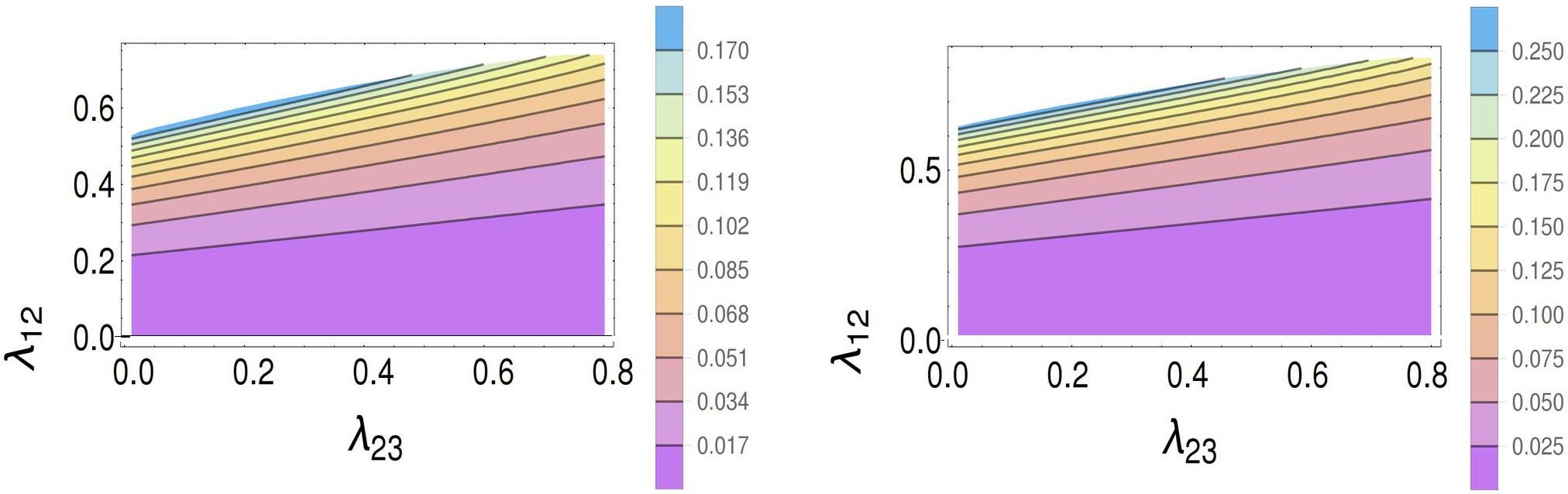
When both C1 and C2 are coupled, the fraction of the current that reaches D as a function of time is
| (2) |
where . Here is the time for the first signal and is the time for one full reflection between B3 and B2. The dc current at D is the zero-frequency limit of the Fourier transform.
| (3) |
Similarly, we calculate the noise at D Martin (2005); Chamon et al. (1995); Berg et al. (2009) via the current-current correlation function on a Schwinger-Keldysh contour to obtain
| (4) |
The noise when one or both of the contacts are decoupled can be computed very similarly SM .
When C2 is decoupled the interactions in region IV are purely density-density, implying that the “charge” of each mode (as previously mentioned, completely independent of electric charge) is conserved. Thus if we sum up all the multiple reflections from boundary B3 and B4 (dc limit), the total “charge” of the neutral reflected from region IV to region III must vanish. Hence the total dc current at D will be zero. The dc current at the drain is only non-zero if and only if both the contacts C1 and C2 are coupled.
III Experimental Realization
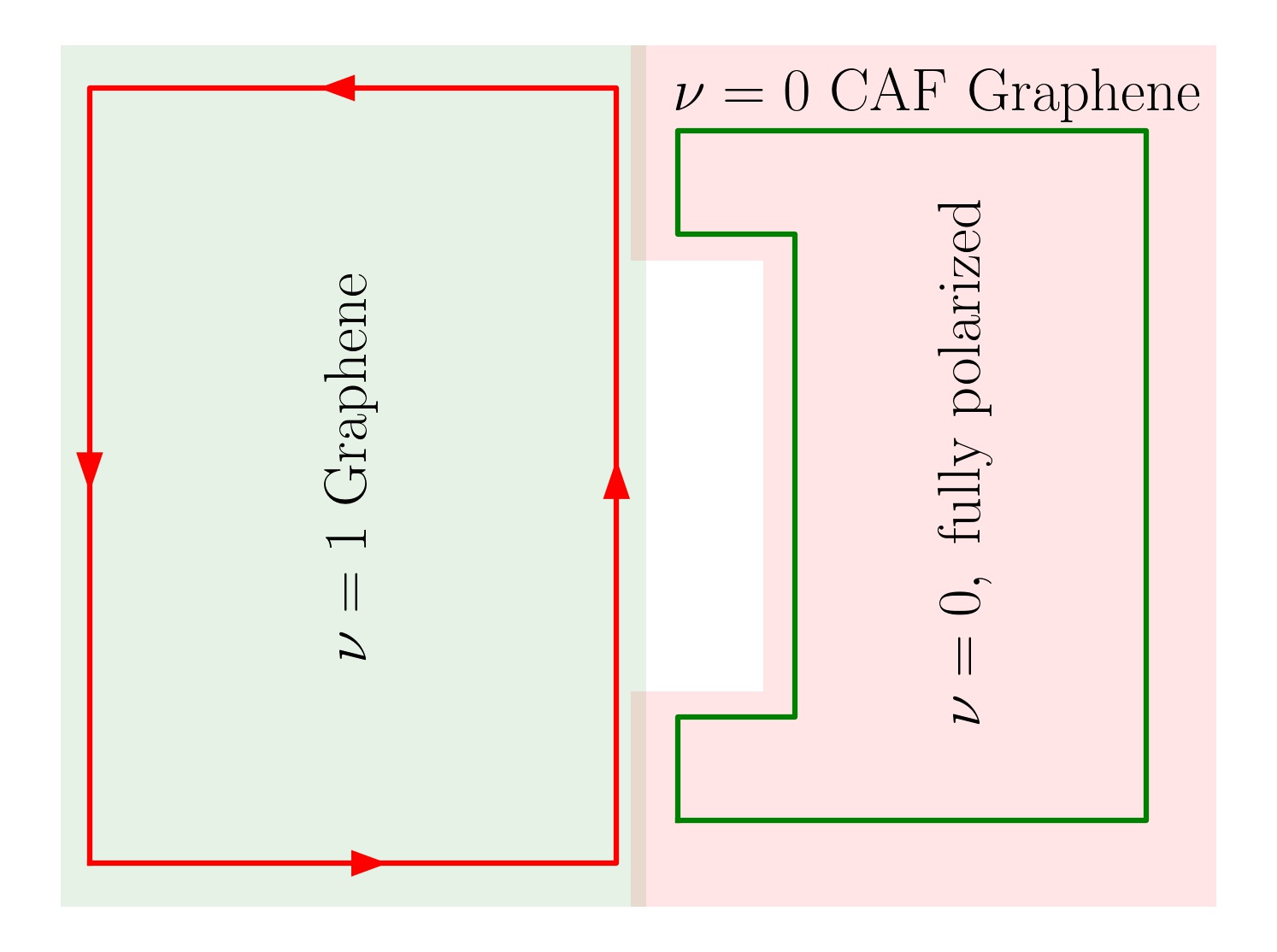
We now discuss an experimental realization of our setup. For monolayer graphene, Hartree-Fock calculations suggest Kharitonov (2012) that at charge neutrality (), there is a quantum phase transition between a canted antiferromagnetic (CAF) phase, stabilized for purely perpendicular magnetic field, and a spin-polarized phase which can be stabilized by increasing the Zeeman energy with an in-plane field. The spin-polarized phase has a fully gapped bulk and a pair of gapless helical edge modes Abanin et al. (2006); Brey and Fertig (2006), whereas the CAF phase breaks U(1) spin-rotation symmetry and has a neutral Goldstone mode in the bulk, but no gapless charged edge modes Murthy et al. (2014, 2016). Experimentally, the phase transition has been seen Young et al. (2014), but evidence that the phase at purely perpendicular is the CAF phase is indirect, via the detection of magnon transmission above the Zeeman energy Wei et al. (2018). Indeed, recent scanning tunneling spectroscopy measurements indicate that the ground state has bond-order Li et al. (2019); Liu et al. (2022); Coissard et al. (2021). To confirm that the system has CAF order one would need to detect gapless collective excitations, as has been done recently in bilayer graphene Fu et al. (2021).
A potential experimental realization of the central idea of this paper is shown in Fig. 3. A sheet of graphene in a perpendicular field is gated such that the left half is at filling , while the right half is at . In the central part of the region, we overlay graphene with a ferromagnetic insulator, whose exchange field makes the graphene under it fully polarized and gapped. However, the annular periphery of region is in the putative CAF phase, with a gapless Goldstone mode. No topological edge modes exist between the two phases at . Confinement in the “radial” direction in the region will reconstruct the continuum of bulk Goldstone modes into bands of clockwise-moving and anticlockwise-moving neutral modes. The lowest two bands will be gapless, and represent the counterpropagating neutral modes in Fig. 1. These counter-propagating neutral modes interact with the charge edge mode of the quantum Hall phase on the left in the regions where they are proximate (Fig. 3). Adding the source S, drain D, and grounded contact G at appropriate locations realizes the setup of Fig. 1, and provides a way to unambiguously detect the gapless neutral Goldstone mode of the CAF.
IV Summary and outlook
In this work we have proposed a setup that has two functionalities: (i) Given a system known to have a neutral mode (the bottom system in Fig. 1), we encode information about the charge current into the neutral current, and subsequently read it out as a dc charge current at a different spatial location. (ii) Given a test system suspected of having coherently propagating, bosonic bos , neutral modes, we place it along the bottom part of Fig. 1 and use our device as a neutral mode detector. An important condition for our protocol to work is that the neutral mode to be detected should counterpropagate with respect to all charge modes, else the charge modes will “short-circuit” the neutral mode. However, measurements of the upstream and downstream charge conductance along the edge of the test system are sufficient to determine whether all charge modes co-propagate in a given system. Backscattering under the contacts breaks the symmetry of each mode; without backscattering no dc current at the drain is possible.
Let us elaborate a bit on the functionality of our setup as a neutral mode detector. Our setup can detect coherently propagating, bosonic bos , neutral edge modes when all the charge modes in the test system are gapped, and gapless modes represent spin/valley fluctuations. Trivial insulators with spontaneous symmetry breaking of a continuous symmetry, such as the putative CAF phase of graphene at charge neutrality, are prime examples of such systems. Moreover, our setup will detect coherently propagating, bosonic, neutral edge modes in QH systems as well, as long as two conditions are met: (i) all chiral charge modes of the test QH system are co-propagating, and (ii) there is at least one neutral mode which counter-propagates with respect to the charge modes. For example, the neutral mode of at the Kane-Fisher-Polchinski fixed point Kane et al. (1994) could be detected by our setup. Using monolayer graphene for the probe system allows one to reverse the propagation direction of the probe charge chiral in situ by gating to obtain in order to realize the geometry of Fig. 1. It must be noted that pairs of neutral edge modes can be generated by edge reconstructions in quantum Hall systems Khanna et al. (2017); Saha et al. (2021). We emphasize that our setup can detect coherently propagating bosonic neutral modes regardless of their physical origin.
Let us compare our setup with previous approaches to neutral mode detection. In one approach, the passage of upstream neutral modes through a quantum point contact was detected through the generation of charge noise Bid et al. (2010, 2009); Cohen et al. (2019); Biswas et al. . More recently, measurements of heat transport “upstream” as compared to charge transport have been employed Yacoby et al. (1994); Banerjee et al. (2017); Srivastav et al. (2021). Not only are these hard measurements, (they require a precise determination of the temperature at a given contact), but they cannot determine whether the heat propagating upstream reflects coherent neutral modes rather than incoherent transport (e.g., due to diffusive modes). The latter is the result of charge and heat equilibration Protopopov et al. (2017); Nosiglia et al. (2018), and also leads to upstream charge noise Spånslätt et al. (2019).
A second theoretical approach for detecting neutral modes in certain quantum Hall systems Feldman and Li (2008); Cano and Nayak (2014) via dc currents depends on tunneling between QH edges at quantum point contacts, and only specific neutral modes in specific configurations lead to dc currents. In our proposal, tunneling between different chiral modes occurs only under the contacts.
There are a few unresolved issues of broad import: (i) How does one understand the formulation of linear and non-linear response in the charge-neutral-charge circuit? (ii) Certain exotic spin systems are believed to have neutral Majorana modes Kitaev (2006); Kasahara et al. (2018), as is the state Banerjee et al. (2017). Our proposed device can detect bosonic bos neutral modes, but can some extension thereof be used to detect Majorana modes as well?
Acknowledgements.
We thank A. Mirlin, I. Gornyi, D. Polyakov, and K. Snizhko for their extremely valuable comments and proposed modifications which significantly improved our manuscript. AD was supported by the German-Israeli Foundation Grant No. I-1505-303.10/2019 and the GIF. AD also thanks Israel planning and budgeting committee (PBC) and Weizmann Institute of Science, Israel Dean of Faculty fellowship, and Koshland Foundation for financial support. YG was supported by CRC 183 of the DFG, the Minerva Foundation, DFG Grant No. MI 658/10-1 and the GIF. SR and GM would like to thank the VAJRA scheme of SERB, India for its support. GM would like to thank the US-Israel Binational Science Foundation for its support via grant no. 2016130, and the Aspen Center for Physics (NSF grant PHY-1607611) where this work was completed.References
- Klitzing et al. (1980) K. v. Klitzing, G. Dorda, and M. Pepper, Phys. Rev. Lett. 45, 494 (1980), URL https://link.aps.org/doi/10.1103/PhysRevLett.45.494.
- Hasan and Kane (2010) M. Z. Hasan and C. L. Kane, Rev. Mod. Phys. 82, 3045 (2010), URL https://link.aps.org/doi/10.1103/RevModPhys.82.3045.
- Bid et al. (2010) A. Bid, N. Ofek, H. Inoue, M. Heiblum, C. L. Kane, V. Umansky, and D. Mahalu, Nature 466, 585 (2010), ISSN 1476-4687, URL https://doi.org/10.1038/nature09277.
- Venkatachalam et al. (2012) V. Venkatachalam, S. Hart, L. Pfeiffer, K. West, and A. Yacoby, Nature Physics 8, 676 (2012), ISSN 1745-2481, URL https://doi.org/10.1038/nphys2384.
- Deviatov et al. (2011) E. V. Deviatov, A. Lorke, G. Biasiol, and L. Sorba, Phys. Rev. Lett. 106, 256802 (2011), URL https://link.aps.org/doi/10.1103/PhysRevLett.106.256802.
- (6) By a bosonic mode we mean a chiral mode that can be described by a chiral boson living on the edge.
- Spånslätt et al. (2021) C. Spånslätt, Y. Gefen, I. V. Gornyi, and D. G. Polyakov, Phys. Rev. B 104, 115416 (2021), URL https://link.aps.org/doi/10.1103/PhysRevB.104.115416.
- Kane and Fisher (1995) C. L. Kane and M. P. A. Fisher, Phys. Rev. B 52, 17393 (1995), URL https://link.aps.org/doi/10.1103/PhysRevB.52.17393.
- Slobodeniuk et al. (2013) A. O. Slobodeniuk, I. P. Levkivskyi, and E. V. Sukhorukov, Phys. Rev. B 88, 165307 (2013), URL https://link.aps.org/doi/10.1103/PhysRevB.88.165307.
- Protopopov et al. (2017) I. Protopopov, Y. Gefen, and A. Mirlin, Annals of Physics 385, 287 (2017), ISSN 0003-4916, URL https://www.sciencedirect.com/science/article/pii/S0003491617302142.
- Nosiglia et al. (2018) C. Nosiglia, J. Park, B. Rosenow, and Y. Gefen, Phys. Rev. B 98, 115408 (2018), URL https://link.aps.org/doi/10.1103/PhysRevB.98.115408.
- Safi and Schulz (1995) I. Safi and H. J. Schulz, Phys. Rev. B 52, R17040 (1995), URL https://link.aps.org/doi/10.1103/PhysRevB.52.R17040.
- Maslov and Stone (1995) D. L. Maslov and M. Stone, Phys. Rev. B 52, R5539 (1995), URL https://link.aps.org/doi/10.1103/PhysRevB.52.R5539.
- Ponomarenko (1995) V. V. Ponomarenko, Phys. Rev. B 52, R8666 (1995), URL https://link.aps.org/doi/10.1103/PhysRevB.52.R8666.
- Oreg and Finkel’stein (1996) Y. Oreg and A. M. Finkel’stein, Phys. Rev. B 54, R14265 (1996), URL https://link.aps.org/doi/10.1103/PhysRevB.54.R14265.
- (16) Supplemental Material.
- Martin (2005) T. Martin, Proceedings of the Les Houches Summer School, Session LXXXI (2005).
- Chamon et al. (1995) C. d. C. Chamon, D. E. Freed, and X. G. Wen, Phys. Rev. B 51, 2363 (1995), URL https://link.aps.org/doi/10.1103/PhysRevB.51.2363.
- Berg et al. (2009) E. Berg, Y. Oreg, E.-A. Kim, and F. von Oppen, Phys. Rev. Lett. 102, 236402 (2009), URL https://link.aps.org/doi/10.1103/PhysRevLett.102.236402.
- Kharitonov (2012) M. Kharitonov, Phys. Rev. B 85, 155439 (2012), URL https://link.aps.org/doi/10.1103/PhysRevB.85.155439.
- Abanin et al. (2006) D. A. Abanin, P. A. Lee, and L. S. Levitov, Phys. Rev. Lett. 96, 176803 (2006), URL https://link.aps.org/doi/10.1103/PhysRevLett.96.176803.
- Brey and Fertig (2006) L. Brey and H. A. Fertig, Phys. Rev. B 73, 195408 (2006), URL https://link.aps.org/doi/10.1103/PhysRevB.73.195408.
- Murthy et al. (2014) G. Murthy, E. Shimshoni, and H. A. Fertig, Phys. Rev. B 90, 241410 (2014), URL https://link.aps.org/doi/10.1103/PhysRevB.90.241410.
- Murthy et al. (2016) G. Murthy, E. Shimshoni, and H. A. Fertig, Phys. Rev. B 93, 045105 (2016), URL https://link.aps.org/doi/10.1103/PhysRevB.93.045105.
- Young et al. (2014) A. F. Young, J. D. Sanchez-Yamagishi, B. Hunt, S. H. Choi, K. Watanabe, T. Taniguchi, R. C. Ashoori, and P. Jarillo-Herrero, Nature 505, 528 (2014), ISSN 1476-4687, URL https://doi.org/10.1038/nature12800.
- Wei et al. (2018) D. S. Wei, T. van der Sar, S. H. Lee, K. Watanabe, T. Taniguchi, B. I. Halperin, and A. Yacoby, Science 362, 229 (2018), eprint https://science.sciencemag.org/content/362/6411/229.full.pdf, URL https://science.sciencemag.org/content/362/6411/229.
- Li et al. (2019) S.-Y. Li, Y. Zhang, L.-J. Yin, and L. He, Phys. Rev. B 100, 085437 (2019), URL https://link.aps.org/doi/10.1103/PhysRevB.100.085437.
- Liu et al. (2022) X. Liu, G. Farahi, C.-L. Chiu, Z. Papic, K. Watanabe, T. Taniguchi, M. P. Zaletel, and A. Yazdani, Science 375, 321 (2022), eprint https://www.science.org/doi/pdf/10.1126/science.abm3770, URL https://www.science.org/doi/abs/10.1126/science.abm3770.
- Coissard et al. (2021) A. Coissard, D. Wander, H. Vignaud, A. G. Grushin, C. Repellin, K. Watanabe, T. Taniguchi, F. Gay, C. Winkelmann, H. Courtois, et al., Imaging tunable quantum hall broken-symmetry orders in charge-neutral graphene (2021), eprint 2110.02811.
- Fu et al. (2021) H. Fu, K. Huang, K. Watanabe, T. Taniguchi, and J. Zhu, Phys. Rev. X 11, 021012 (2021), URL https://link.aps.org/doi/10.1103/PhysRevX.11.021012.
- Kane et al. (1994) C. L. Kane, M. P. A. Fisher, and J. Polchinski, Phys. Rev. Lett. 72, 4129 (1994), URL https://link.aps.org/doi/10.1103/PhysRevLett.72.4129.
- Khanna et al. (2017) U. Khanna, G. Murthy, S. Rao, and Y. Gefen, Phys. Rev. Lett. 119, 186804 (2017), URL https://link.aps.org/doi/10.1103/PhysRevLett.119.186804.
- Saha et al. (2021) A. Saha, S. J. De, S. Rao, Y. Gefen, and G. Murthy, Phys. Rev. B 103, L081401 (2021), URL https://link.aps.org/doi/10.1103/PhysRevB.103.L081401.
- Bid et al. (2009) A. Bid, N. Ofek, M. Heiblum, V. Umansky, and D. Mahalu, Phys. Rev. Lett. 103, 236802 (2009), URL https://link.aps.org/doi/10.1103/PhysRevLett.103.236802.
- Cohen et al. (2019) Y. Cohen, Y. Ronen, W. Yang, D. Banitt, J. Park, M. Heiblum, A. D. Mirlin, Y. Gefen, and V. Umansky, Nature Communications 10, 1920 (2019), ISSN 2041-1723, URL https://doi.org/10.1038/s41467-019-09920-5.
- (36) S. Biswas, A. Das, H. K. Kundu, Y. Gefen, and M. Heiblum, in preparation.
- Yacoby et al. (1994) A. Yacoby, M. Heiblum, H. Shtrikman, V. Umansky, and D. Mahalu, Semiconductor Science and Technology 9, 907 (1994).
- Banerjee et al. (2017) M. Banerjee, M. Heiblum, A. Rosenblatt, Y. Oreg, D. E. Feldman, A. Stern, and V. Umansky, Nature 545, 75 (2017), ISSN 1476-4687, URL https://doi.org/10.1038/nature22052.
- Srivastav et al. (2021) S. K. Srivastav, R. Kumar, C. Spånslätt, K. Watanabe, T. Taniguchi, A. D. Mirlin, Y. Gefen, and A. Das, Phys. Rev. Lett. 126, 216803 (2021), URL https://link.aps.org/doi/10.1103/PhysRevLett.126.216803.
- Spånslätt et al. (2019) C. Spånslätt, J. Park, Y. Gefen, and A. D. Mirlin, Phys. Rev. Lett. 123, 137701 (2019), URL https://link.aps.org/doi/10.1103/PhysRevLett.123.137701.
- Feldman and Li (2008) D. E. Feldman and F. Li, Phys. Rev. B 78, 161304 (2008), URL https://link.aps.org/doi/10.1103/PhysRevB.78.161304.
- Cano and Nayak (2014) J. Cano and C. Nayak, Phys. Rev. B 90, 235109 (2014), URL https://link.aps.org/doi/10.1103/PhysRevB.90.235109.
- Kitaev (2006) A. Kitaev, Annals of Physics 321, 2 (2006), ISSN 0003-4916, january Special Issue, URL https://www.sciencedirect.com/science/article/pii/S0003491605002381.
- Kasahara et al. (2018) Y. Kasahara, T. Ohnishi, Y. Mizukami, O. Tanaka, S. Ma, K. Sugii, N. Kurita, H. Tanaka, J. Nasu, Y. Motome, et al., Nature 559, 227 (2018), ISSN 1476-4687, URL https://doi.org/10.1038/s41586-018-0274-0.
See pages 1 of Supl
See pages 2 of Supl
See pages 3 of Supl
See pages 4 of Supl