Extracellular electrical stimulation by ferroelectric displacement current in the switching regime
Abstract
We analyze the extracellular stimulation current and the charge injection capacitity (CIC) of microelectrodes coated with an insulating layer to prevent toxic electrochemical effects in bioelectronic applications. We show for a microelectrode coated with an insulating ferroelectric layer, that the ferroelectric polarization current contributes to the extracellular stimulation current. Depending on the remanent polarization of the ferroelectric, the polarization current in the switching regime can increase the CIC by up to two orders of magnitude as compared to the commonly used extracellular capacitive stimulation with microelectrodes that are coated with a dielectric layer.
Extracellular electrical stimulation of neurons and recording of neural activity are the basic principles for many in vivo applications such as implantable neuroprosthetic devices Cogan (2008). Among them are cochlear implants, retinal implants, deep brain stimulation for the treatment of Parkinsons’s disease and brain-machine interfaces Kral et al. (2019); Zrenner et al. (2011); Mathieson et al. (2012); Yue et al. (2020); Miocinovic et al. (2013); et al. (2019). Moreover, extracellullar electrical stimulation and recording are also key elements for in vitro applications e.g. drug testing and the study of neural networks by microelectrode arrays (MEAs) Stett et al. (2003); Frey et al. (2009).
Typically, electrically active implants and MEAs utilize conductive (metallic) microelelectrodes with diameter 100 m to provide the electro–neural interface for extracellular recording and stimulation Cogan (2008). In general, the main advantage of conductive microelectrodes is their high charge injection capacity (CIC), which is defined as the amount of injected charge density across the electrode–elelctrolyte interface during the leading stimulation phase of an extracellular current Cogan (2008). Exemplary materials for the fabrication of conductive microelectrodes are Pt for high-density MEA applications Frey et al. (2009) and IrO2 which is utilized e.g. in state-of-the-art retinal prostheses Mathieson et al. (2012); Haas et al. (2020) and which can provide a CIC typically in the range of 1 - 5 mC/cm2 Cogan (2008); Maeng et al. (2019); Haas et al. (2020).
The major disadvantage of conductive microelectrodes is the difficulty to avoid electrochemical reactions (Faradaic processes) at the electrode–electrolyte interface, which induce corrosion of electrodes and cell or tissue damage Merrill et al. (2005) and hence affect detrimentally the safety and long-term-stability of implantable neuroprosthetic devices. A possible solution to prevent toxic electrochemical effects is the utilization of microelectrodes coated with a (thin) dielectric material. This approach was crucial for the first realization of a silicon–neuron junction, where -doped areas of the utilized silicon chip were covered with a 10-nm-thick dielectric layer of SiO2 to prevent Faradaic processes and to stimulate the attached neuron by purely capacitive currents across the dielectric–electrolyte interface Fromherz and Stett (1995).
Modern capacitive biochips for extracellular electrical stimulation are fabricated in complementary metal-oxide-semiconductor (CMOS) technology and include field-effect transistors to record electrical signals from individual neurons Fromherz et al. (1991), which enables the bidirectional communication between neurons and active silicon chips Bertotti et al. (2014). However, despite extensive research for dielectric coatings to enhance the purely capacitive stimulation with microelectrodes, their CIC is still in the range of 1 - 5 C/cm2 Wallrapp and Fromherz (2006); Schoen and Fromherz (2007); Eickenscheidt et al. (2012); Bertotti et al. (2014); Dollt et al. (2020), which is approximately three orders of magnitude lower than the CIC of generic conductive microelectrodes. Since the stimulation-threshold for the injected charge density depends on the geometric area of the microelectrode Corna et al. (2018), the CIC of capacitive microelectrodes is too low to achieve efficient extracellular stimulation with small microelectrodes (diameter 30 m) which requires a CIC in the range of 0.1 - 0.9 mC/cm2 Corna et al. (2018), although a tight tissue–electrode contact can lower the stimulation-threshold Eickenscheidt et al. (2012). As a consequence, implantable neuroprosthetic devices utilize conductive metal-based microelectrodes although the absence of toxic electrochemical effects is highly desired in active electrical implants. In this letter, we introduce an approach to significantly increase the CIC of insulated microelectrodes for efficient and long-term stable bioelectronic interfacing of electrogenic cells or tissue.
In general, extracellular electrical stimulation is achieved by the flow of ionic current between a microelectrode in close proximity to the target excitable cell or tissue and a counter electrode immersed in the electrolyte, which contains the cell or tissue Cogan (2008). The ionic current flow in proximity to the cell or tissue causes a depolarization of the cell membrane, which evokes an action potential above a specific threshold.
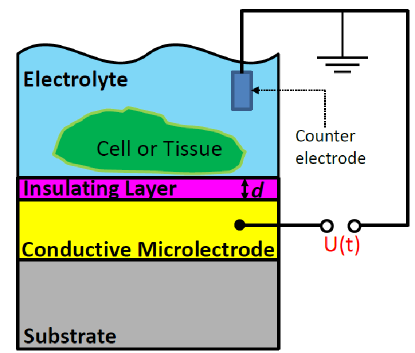
A schematic experimental set-up for the extracellular electrical stimulation of electrogenic cells or tissue with insulated microelectrodes in a parallel-plate configuration with insulator thickness is depicted in Fig. 1. Here, an applied voltage signal generates an electric field across the insulating layer, which results in the occurrence of bound polarization charges at the surface of the insulator. As a consequence, a flow of free charges in the electrolyte is generated to screen the bound polarization charges, and this ionic current corresponds to the extracellular stimulation current. A simple stimulation signal is a voltage step , where denotes the Heaviside function. Other generic voltage signals for extracellular stimulation are rectangular voltage pulses with stimulation time 1 ms, which are utilized in retinal implants Zrenner et al. (2011) or deep brain stimulation Miocinovic et al. (2013).
In the following, we will analyze the experimental set-up for extracellular electrical stimulation with insulated microelectrodes [cf. Fig. 1] within the framework of macroscopic electrodynamics Brandt and Dahmen (2005). We make the assumption, that every vector quantity is fully described by its component normal to the plane of the insulating layer and all other components vanish. The focus of our analysis will be the insulating layer depicted in Fig. 1, which is described by the electric displacement field defined as Brandt and Dahmen (2005)
| (1) |
with the vacuum permittivity and electrical polarization . We assume that the insulating layer has an infinite Ohmic resistance, which requires the absence of free charges, i.e. . We now consider Ampère’s law, which is part of the macroscopic Maxwell equations and is given by Brandt and Dahmen (2005)
| (2) |
with the magnetic field strength , the conduction current density and the time derivative , which corresponds to the density of Maxwell’s displacement current. Due to the insulation of the conductive microelectrode [cf. Fig. 1] electrochemical (Faradaic) charge transport is suppressed, which results in a vanishing conduction current density in Eq. (2). Thus, the extracellular stimulation current density provided by an insulated microelectrode corresponds to the displacement current density, i.e. and by definition, the CIC can be calculated according to
| (3) |
The common extracellular capacitive stimulation utilizes an insulating layer which consists of a material with solely dielectric properties. In linear approximation, the electrical polarization of a dielectric material is given by Brandt and Dahmen (2005)
| (4) |
where denotes the relative permittivity of the material. Inserting Eq. (4) in Eq. (1) yields the linear relationship
| (5) |
By introducing the specific capacitance , the resulting capacitive stimulation current density in repsonse to a time-varying electric field is then given by
| (6) |
Thus, previous attempts to enhance the CIC of capacitive microelectrodes were based on the approach to increase the specific capacitance of the dielectric layer.
We now consider a material with ferroelectric properties. Ferroelectrics are characterized by the existence of a (spontaneous) ferroelectric polarization , which can be reoriented by an applied electric field, i.e. Waser et al. (2005). The finite value of the ferroelectric polarization at zero electric field is called the remanent polarization . By applying an electric field above the coervice field of the ferroelectric, the remanent polarization can be switched between the bistable states , which is the basis for nonvolatile ferroelectric memory applications Park et al. (2018). Here, the discovery of ferroelectricity in HfO2-based thin films represents a real breakthrough due to the full CMOS compatibility of this material class and outstanding ferroelectric properties at the nanoscale Müller et al. (2011); Park et al. (2018); Wei et al. (2018). Moreover, conventional dielectric HfO2 layers have been previously utilized in capacitive biochips Wallrapp and Fromherz (2006); Schoen and Fromherz (2007); Dollt et al. (2020), which demonstrates their biocompatibility. Note, that materials with ferroelectric properties also exhibit dielectric properties but not vice versa. Thus, the electrical polarization of a material with ferroelectric properties is given by . As a consequence, it follows from Eq. (1)
| (7) |
and the resulting ferroelectric displacement current density for extracellular stimulation in repsonse to a time-varying electric field is then given by
| (8) |
which exhibits the ferroelectric polarization current as an additional contribution as compared to the purely capacitive stimulation current density Eq. (6).
Depending on the applied electric field strength , we can identify two different regimes of the ferroelectric polarization current which are separated by the coercive field of the ferroelectric, i.e.
| (9) |
where corresponds to the subswitching regime and to the switching regime of the ferroelectric. For subswitching fields above a specific threshold field the linear approximation Eq. (4) is no longer valid for a ferroelectric material due to the irreversible motion of ferroelectric domain walls, which results in a nonlinear vs relationship described by the Rayleigh law Damjanovic (1998). As a consequence, the ferroelectric displacement current density Eq. (8) in response to a harmonic ac electric field can contain higher harmonics due to the contribution from irreversible domain wall motion contained in Miga et al. (2007), which might be interesting for extracellular stimulation with low-frequency sinusoidal voltage signals Freeman et al. (2010). Experimentally, the subswitching regime of a ferroelectric can be analyzed in detail by impedance spectroscopy and equivalent-circuit fitting with the recently introduced domain wall pinning element Becker et al. (2020).
In the following, we will focus our discussion on the ferroelectric switching regime . The corresponding switching kinetics is a very complex problem and there exist several models to explain the time-dependence of ferroelectric polarization reversal Jo et al. (2007). The traditional approach to explain the switching kinetics is the Kolmogorov-Avrami-Ishibashi (KAI)-model Kolmogorov (1937); Avrami (1939); Ishibashi and Takagi (1971), which is based on the classical statistical theory of nucleation and predicts for the time-dependent change in ferroelectric polarization during switching between the bistable states , the relationship Jo et al. (2007)
| (10) |
with the effective dimension and the characteristic switching time as free parameters. For thin films, the effective dimension is = 2 Jo et al. (2007) and the time-dependence of the magnitude of the corresponding switching current density is then given by
| (11) |
| (nm) | (C/cm2) | (MV/cm) | (s) | r (m) | (cm) | (V) | |
|---|---|---|---|---|---|---|---|
| 9.5 | 16 | 1 | 10 | 40 | 25 | 66.7 | 1 |
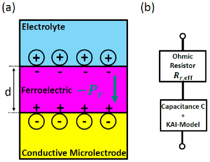
We now reconsider the schematic experimental set-up for extracellular stimulation depicted in Fig. 1 with the specification that the conductive microelectrode with radius and geometrical surface area is insulated with a ferroelectric layer, which corresponds to the electrolyte–ferroelectric–conductor (EFC) configuration shown in Fig. 2(a). To analyze the CIC and the time-dependence of the stimulation current density provided by the EFC configuration in the switching regime , we describe the EFC configuration by the equivalent-circuit depicted in Fig. 2(b). Here, the Ohmic resistance models the electrolyte and the electrodes and the capacitance in combination with the KAI-model models the ferroelectric layer of the EFC configuration. The Ohmic resistance can be approximated by the effective resistance for a circular microelectrode with radius and an adjacent electrolyte with specific resistance according to Chen et al. (2020)
| (12) |
The stimulation current density provided by the EFC configuration [cf. Fig. 2] in response to an applied voltage step with height , which induces polarization reversal from the initial state - to the final state + is then given by
where the first term in Eq. (LABEL:eq:J_stim) is the capacitive transient . Note, that ferroelectric polarization reversal in EFC configuration has been demonstrated for various ferroelectric materials Ferris et al. (2013); Fabiano et al. (2014); Toss et al. (2017).
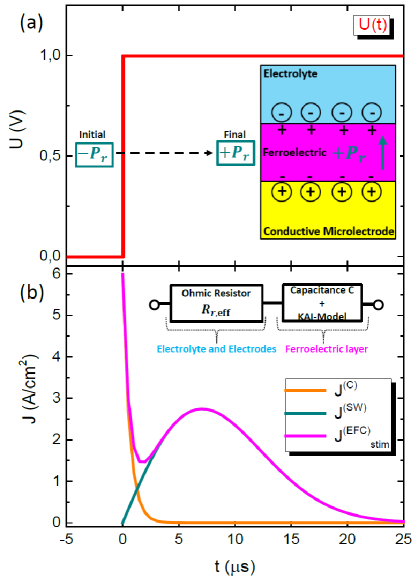
To simulate the extracellular stimulation current response of an insulated microelectrode in EFC configuration [cf. Fig. 2] during polarization reversal, we utilize Eq. (LABEL:eq:J_stim) with the specifications summarized in Table 1. The applied voltage step with height = 1 V depicted in Fig. 3(a), generates an electric field above the coercive field of the ferroelectric layer [cf. Table 1] and the resulting current response in the switching regime is shown in Fig. 3(b). Here, the capacitive transient is superimposed by the bell-shaped switching current density and the resulting CIC Eq. (3) for complete switching during the stimulation time (i.e. ) is given by Damjanovic (1998)
| (14) |
which exhibits the additional contribution compared to the CIC of microelectrodes with dielectric coating for extracellular capacitive stimulation Fromherz and Stett (1995). Note that repetetive stimulation with a CIC according to Eq. (14) requires a subsequent voltage pulse of opposite polarity to reorient the remanent polarization back to its initial state. This is not necessary for antiferroelectric materials or ferroelectrics in the paraelectric phase, where the remanent polarization is zero and which might be interesting alternatives for stimulation with solely unipolar voltage signals.
For a ferroelectric microelectrode with the specifications listed in Table 1, Eq. (14) yields a CIC of 35.7 C/cm2, which is dominated by the contribution . Therefore, another interesting CMOS compatible material class is Al1-xScxN, which exhibit ferroelectric properties with up to 110 C/cm2 Fichtner et al. (2019) resulting in a CIC above 200 C/cm2, which is in the range of previously reported stimulation-thresholds for small conductive microelectrodes (30 m in diameter) Corna et al. (2018) and which is approximately two orders of magnitude above the CIC of state-of-the-art capacitive microelectrodes Wallrapp and Fromherz (2006); Schoen and Fromherz (2007); Eickenscheidt et al. (2012); Bertotti et al. (2014); Dollt et al. (2020). Note, that the CIC of ferroelectric microelectrodes might be further increased by the fabrication of 3D structures Park et al. (2018).
In conclusion, our results pave the way to utilize ferroelectrics for bioelectronic interfacing of electrogenic cells or tissue. The resulting ferroelectric–neural interface is a promising approach for extracellular electrical stimulation without toxic electrochemical effects, which is crucial for implantable neuroprosthetic devices such as retinal-implants or brain-machine interfaces. Clearly, substantial future work is needed to develop stimulus protocols for specific neuronal classes and for different ferroelectric materials with different remanent polarization and switching kinetics. Additional possibilities for future studies on ferroelectric–neural interfaces are extracellular electrical recordings by utilizing the ferroelectric layer as gate oxide of a ferroelectric field-effect transistor (FeFET), which polarization state is sensitive to extracellular potentials generated by adjacent neurons. This might result in the coupling of artificial neurons based on FeFETs Mulaosmanovic et al. (2018) with biological neurons for future neuromorphic computing applications.
The author thanks Claus Burkhardt and Dieter Koelle for very fruitful discussions.
Data availability
The data that supports the findings of this study are available within the article.
References
- Cogan (2008) S. F. Cogan, “Neural stimulation and recording electrodes,” Annu. Rev. Biomed. Eng. 10, 275 (2008).
- Kral et al. (2019) A. Kral, M. F. Dorman, and B. S. Wilson, “Neuronal development of hearing and language: Cochlear implants and critical periods,” Annu. Rev. Neurosci. 42, 47 (2019).
- Zrenner et al. (2011) E. Zrenner, K. U. Bartz-Schmidt, H. Benav, D. Besch, A. Bruckmann, V-P. Gabel, F. Gekeler, U. Greppmaier, A. Harscher, S. Kibbel, J. Koch, A. Kusnyerik, T. Peters, K. Stingl, H. Sachs, A. Stett, P. Szurman, B. Wilhelm, and R. Wilke, “Subretinal electronic chips allow blind patients to read letters and combine them to words,” Proc. R. Soc. B 278, 1489 (2011).
- Mathieson et al. (2012) K. Mathieson, J. Loudin, G. Goetz, P. Huie, L. Wang, T. I. Kamins, L. Galambos, R. Smith, J. S. Harris, A. Sher, and D. Palanker, “Photovoltaic retinal prosthesis with high pixel density,” Nature Photonics 6, 391 (2012).
- Yue et al. (2020) L. Yue, V. Wuyyuru, A. Gonzalez-Calle, J. D. Dorn, and M. S. Humayun, “Retina-electrode interface properties and vision restoration by two generations of retinal prostheses in one patient – one in each eye,” J. Neural Eng. 17, 026020 (2020).
- Miocinovic et al. (2013) S. Miocinovic, S. Somayajula, S. Chitnis, and J. Vitek, “History, applications, and mechanisms of deep brain stimulation,” JAMA Neurol. 70, 163 (2013).
- et al. (2019) E. Musk et al., “An integrated brain-machine interface platform with thousands of channels,” bioRxiv , 703801 (2019).
- Stett et al. (2003) A. Stett, U. Egert, E. Guenther, F. Hofmann, T. Meyer, W. Nisch, and H. Haemmerle, “Biological application of microelectrode arrays in drug discovery and basic research,” Anal. Bioanal. Chem. 377, 486 (2003).
- Frey et al. (2009) U. Frey, U. Egert, F. Heer, S. Hafizovic, and A. Hierlemann, “Microelectronic system for high-resolution mapping of extracellular electric fields applied to brain slices,” Biosensors and Bioelectronics 24, 2191 (2009).
- Haas et al. (2020) J. Haas, R. Rudorf, M. Becker, R. Daschner, A. Drzyzga, C. Burkhardt, and A. Stett, “Sputtered iridium oxide as electrode material for subretinal stimulation,” Sens. Mater. 32, 2903 (2020).
- Maeng et al. (2019) J. Maeng, B. Chakraborty, N. Geramifard, T. Kang, R. T. Rihani, A. Joshi-Imre, and S. F. Cogan, “High-charge-capacity sputtered iridium oxide neural stimulation electrodes deposited using water vapor as a reactive plasma constituent,” J. Biomed. Mater. Res. 108B, 880 (2019).
- Merrill et al. (2005) D. R. Merrill, M. Bikson, and J. G. R. Jefferys, “Electrical stimulation of excitable tissue: design of efficacious and safe protocols,” J. Neurosci. Methods 141, 171 (2005).
- Fromherz and Stett (1995) P. Fromherz and A. Stett, “Silicon-Neuron Junction: Capacitive Stimulation of an Individual Neuron on a Silicon Chip,” Phys. Rev. Lett. 75, 1670 (1995).
- Fromherz et al. (1991) P. Fromherz, A. Offenhäusser, T. Vetter, and J. Weis, “A Neuron-Silicon Junction: A Retzius Cell of the Leech on an Insulated-Gate Field-Effect Transistor,” Science 252, 1290 (1991).
- Bertotti et al. (2014) G. Bertotti, D. Velychko, N. Dodel, S. Keil, D. Wolansky, B. Tillak, M. Schreiter, A. Grall, P. Jesinger, S. Röhler, M. Eickenscheidt, A. Stett, A. Möller, K-H. Boven, G. Zeck, and R. Thewes, “A CMOS-Based Sensor Array for In-Vitro Neural Tissue Interfacing with 4225 Recording Sites and 1024 Stimulation Sites,” in 2014 IEEE Biomedical Circuits and Systems Conference (BioCAS) Proceedings (2014).
- Wallrapp and Fromherz (2006) F. Wallrapp and P. Fromherz, “TiO2 and HfO2 in electrolyte-oxide-silicon configuration for applications in bioelectronics,” J. Appl. Phys. 99, 114103 (2006).
- Schoen and Fromherz (2007) I. Schoen and P. Fromherz, “The mechanism of extracellular stimulation of nerve cells on an electrolyte-oxide-semiconductor capacitor,” Biophysical Journal 92, 1096 (2007).
- Eickenscheidt et al. (2012) M. Eickenscheidt, M. Jenkner, R. Thewes, P. Fromherz, and G. Zeck, “Electrical stimulation of retinal neurons in epiretinal and subretinal configuration using a multicapacitor array,” J. Neurophysiol. 107, 2742 (2012).
- Dollt et al. (2020) M. Dollt, M. Reh, M. Metzger, G. Heusel, M. Kriebel, V. Bucher, and G. Zeck, “Low-Temperature Atomic Layer Deposited Oxide on Titanium Nitride Electrodes Enables Culture and Physiological Recording of Electrogenic Cells,” Front. Neurosci. 14, 552876 (2020).
- Corna et al. (2018) A. Corna, T. Herrmann, and G. Zeck, “Electrode-size dependent thresholds in subretinal neuroprosthetic stimulation,” J. Neural Eng. 15, 045003 (2018).
- Brandt and Dahmen (2005) S. Brandt and H. D. Dahmen, Elektrodynamik, 4th ed. (Springer, Berlin, 2005).
- Waser et al. (2005) R. Waser, U. Böttger, and S. Tiedke (Ed.), Polar Oxides, 1st ed. (Wiley, New York, 2005).
- Park et al. (2018) M. H. Park, Y. H. Lee, T. Mikolajick, U. Schroeder, and C. S. Hwang, “Review and perspective on ferroelectric HfO2-based thin films for memory applications,” MRS Communications 8, 795 (2018).
- Müller et al. (2011) J. Müller, T. S. Böschke, D. Bräuhaus, U. Schröder, U. Böttger, J. Sundqvist, P. Kücher, T. Mikolajick, and L. Frey, “Ferroelectric Zr0.5Hf0.5O2 thin films for nonvolatile memory applications,” Appl. Phys. Lett. 99, 112901 (2011).
- Wei et al. (2018) Y. Wei, P. Nukala, M. Salverda, S. Matzen, H. J. Zhao, J. Momand, A. S. Everhardt, G. Agnus, G. R. Blake, P. Lecoeur, B. J. Kooi, J. Íñiguez, B. Dkhil, and B. Noheda, “A rhombohedral ferroelectric phase in epitaxially strained Hf0.5Zr0.5O2 thin films,” Nature Materials 17, 1095 (2018).
- Damjanovic (1998) D. Damjanovic, “Ferroelectric, dielectric and piezoelectric properties of ferroelectric thin films and ceramics,” Rep. Progr. Phys. 61, 1267 (1998).
- Miga et al. (2007) S. Miga, J. Dec, and W. Kleemann, “Computer-controlled susceptometer for investigating the linear and nonlinear dielectric response,” Rev. Sci. Instrum. 78, 033902 (2007).
- Freeman et al. (2010) D. K. Freeman, D. K. Eddington, J. F. Rizzo III, and S. I. Fried, “Selective activation of neuronal targets with sinusoidal electric stimulation,” J. Neurophysiol. 104, 2778 (2010).
- Becker et al. (2020) M. Becker, C. J. Burkhardt, B. Schröppel, R. Kleiner, and D. Koelle, “Rayleigh analysis and dielectric dispersion in polycrystalline 0.5(Ba0.7Ca0.3)TiO3–0.5Ba(Zr0.2Ti0.8)O3 ferroelectric thin films by domain-wall pinning element modeling,” J. Appl. Phys. 128, 154103 (2020).
- Jo et al. (2007) J. Y. Jo, H. S. Han, J.-G. Yoon, T. K. Song, S.-H. Kim, and T. W. Noh, “Domain switching kinetics in disordered ferroelectric thin films,” Phys. Rev. Lett. 99, 267602 (2007).
- Kolmogorov (1937) A. N. Kolmogorov, “Statistical theory of nucleation processes,” Bull. Acad. Sci. USSR Math. Ser. 3, 355 (1937).
- Avrami (1939) M. Avrami, “Kinetics of phase change. I General theory,” J. Chem. Phys. 7, 1103 (1939).
- Ishibashi and Takagi (1971) Y. Ishibashi and Y. Takagi, “Note on ferroelectric domain switching,” J. Phys. Soc. Jpn. 31, 506 (1971).
- Chen et al. (2020) Z. Chen, L. Ryzhik, and D. Palanker, “Current distribution on capacitive electrode-electrolyte interfaces,” Phys. Rev. Applied 13, 014004 (2020).
- Ferris et al. (2013) R. J. Ferris, S. Lin, M. Therezien, B. B. Yellen, and S. Zauscher, “Electric double layer formed by polarized ferroelectric thin films,” ACS Appl. Mater. Interfaces 5, 2610 (2013).
- Fabiano et al. (2014) S. Fabiano, X. Crispin, and M. Berggren, “Ferroelectric Polarization Induces Electric Double Layer Bistability in Electrolyte-Gated Field-Effect Transistors,” ACS Appl. Mater. Interfaces 6, 438 (2014).
- Toss et al. (2017) H. Toss, S. Lönnqvist, D. Nilsson, A. Sawatdee, J. Nissa, S. Fabiano, M. Berggren, G. Kratz, and D. T. Simon, “Ferroelectric surfaces for cell release,” Synthetic Metals 228, 99 (2017).
- Fichtner et al. (2019) S. Fichtner, N. Wolff, F. Lofink, L. Kienzle, and B. Wagner, “AlScN: A III-V semiconductor based ferroelectric,” J. Appl. Phys. 125, 114103 (2019).
- Mulaosmanovic et al. (2018) H. Mulaosmanovic, E. Chicca, M. Bertele, T. Mikolajick, and S. Slesazeck, “Mimicking biological neurons with a nanoscale ferroelectric transistor,” Nanoscale 10, 21755 (2018).