1.25em
\SetWatermarkText ![[Uncaptioned image]](/html/2103.03443/assets/x1.png) \SetWatermarkAngle0
\SetWatermarkAngle0
Lord of the Ring(s):
Side Channel Attacks on the
CPU On-Chip Ring Interconnect Are Practical
Abstract
We introduce the first microarchitectural side channel attacks that leverage contention on the CPU ring interconnect. There are two challenges that make it uniquely difficult to exploit this channel. First, little is known about the ring interconnect’s functioning and architecture. Second, information that can be learned by an attacker through ring contention is noisy by nature and has coarse spatial granularity. To address the first challenge, we perform a thorough reverse engineering of the sophisticated protocols that handle communication on the ring interconnect. With this knowledge, we build a cross-core covert channel over the ring interconnect with a capacity of over 4 Mbps from a single thread, the largest to date for a cross-core channel not relying on shared memory. To address the second challenge, we leverage the fine-grained temporal patterns of ring contention to infer a victim program’s secrets. We demonstrate our attack by extracting key bits from vulnerable EdDSA and RSA implementations, as well as inferring the precise timing of keystrokes typed by a victim user.
(88pt,-414pt) This is the extended version of a paper that appears in USENIX Security 2021
1 Introduction
Modern computers use multicore CPUs that comprise several heterogeneous, interconnected components often shared across computing units. While such resource sharing has offered significant benefits to efficiency and cost, it has also created an opportunity for new attacks that exploit CPU microarchitectural features. One class of these attacks consists of software-based covert channels and side channel attacks. Through these attacks, an adversary exploits unintended effects (e.g., timing variations) in accessing a particular shared resource to surreptitiously exfiltrate data (in the covert channel case) or infer a victim program’s secrets (in the side channel case). These attacks have been shown to be capable of leaking information in numerous contexts. For example, many cache-based side channel attacks have been demonstrated that can leak sensitive information (e.g., cryptographic keys) in cloud environments [85, 115, 108, 51, 65], web browsers [77, 89, 40, 61] and smartphones [93, 62].
Fortunately, recent years have also seen an increase in the awareness of such attacks, and the availability of countermeasures to mitigate them. To start with, a large number of existing attacks (e.g., [38, 39, 8, 16, 81, 6, 27, 28]) can be mitigated by disabling simultaneous multi-threading (SMT) and cleansing the CPU microarchitectural state (e.g., the cache) when context switching between different security domains. Second, cross-core cache-based attacks (e.g., [65, 22, 41]) can be blocked by partitioning the last-level cache (e.g., with Intel CAT [74, 64]), and disabling shared memory between processes in different security domains [102]. The only known attacks that would still work in such a restrictive environment (e.g., DRAMA [83]) exist outside of the CPU chip.
In this paper, we present the first on-chip, cross-core side channel attack that works despite the above countermeasures. Our attack leverages contention on the ring interconnect, which is the component that enables communication between the different CPU units (cores, last-level cache, system agent, and graphics unit) on many modern Intel processors. There are two main reasons that make our attack uniquely challenging. First, the ring interconnect is a complex architecture with many moving parts. As we show, understanding how these often-undocumented components interact is an essential prerequisite of a successful attack. Second, it is difficult to learn sensitive information through the ring interconnect. Not only is the ring a contention-based channel—requiring precise measurement capabilities to overcome noise—but also it only sees contention due to spatially coarse-grained events such as private cache misses. Indeed, at the outset of our investigation it was not clear to us whether leaking sensitive information over this channel would even be possible.
To address the first challenge, we perform a thorough reverse engineering of Intel’s “sophisticated ring protocol” [90, 60] that handles communication on the ring interconnect. Our work reveals what physical resources are allocated to what ring agents (cores, last-level cache slices, and system agent) to handle different protocol transactions (loads from the last-level cache and loads from DRAM), and how those physical resources arbitrate between multiple in-flight transaction packets. Understanding these details is necessary for an attacker to measure victim program behavior. For example, we find that the ring prioritizes in-flight over new traffic, and that it consists of two independent lanes (each with four physical sub-rings to service different packet types) that service interleaved subsets of agents. Contrary to our initial hypothesis, this implies that two agents communicating “in the same direction, on overlapping ring segments” is not sufficient to create contention. Putting our analysis together, we formulate for the first time the necessary and sufficient conditions for two or more processes to contend with each other on the ring interconnect, as well as plausible explanations for what the ring microarchitecture may look like to be consistent with our observations. We expect the latter to be a useful tool for future work that relies on the CPU uncore.
Next, we investigate the security implications of our findings. First, leveraging the facts that i) when a process’s loads are subject to contention their mean latency is larger than that of regular loads, and ii) an attacker with knowledge of our reverse engineering efforts can set itself up in such a way that its loads are guaranteed to contend with the first process’ loads, we build the first cross-core covert channel on the ring interconnect. Our covert channel does not require shared memory (as, e.g., [111, 41]), nor shared access to any uncore structure (e.g., the RNG [25]). We show that our covert channel achieves a capacity of up to 4.14 Mbps (518 KBps) from a single thread which, to our knowledge, is faster than all prior channels that do not rely on shared memory (e.g., [83]), and within the same order of magnitude as state-of-the-art covert channels that do rely on shared memory (e.g., [41]).
Finally, we show examples of side channel attacks that exploit ring contention. The first attack extracts key bits from vulnerable RSA and EdDSA implementations. Specifically, it abuses mitigations to preemptive scheduling cache attacks to cause the victim’s loads to miss in the cache, monitors ring contention while the victim is computing, and employs a standard machine learning classifier to de-noise traces and leak bits. The second attack targets keystroke timing information (which can be used to infer, e.g., passwords [114, 91, 59]). In particular, we discover that keystroke events cause spikes in ring contention that can be detected by an attacker, even in the presence of background noise. We show that our attack implementations can leak key bits and keystroke timings with high accuracy. We conclude with a discussion of mitigations.
2 Background and Related Work
CPU Cache Architecture
CPU caches on modern x86 Intel microarchitectures are divided in L1, L2 and L3 (often called last-level cache or LLC). The L1 and (in most microarchitectures) L2 caches are fast (4 to 12 cycles), small, and local to each CPU core. They are often referred to as private caches. The LLC is slower (40 to 60 cycles), bigger, and shared across CPU cores. Since Nehalem-EX [57], the LLC is divided into LLC slices of equal size, one per core.
Caches of many Intel CPUs are inclusive, meaning that data contained in the L1 and L2 caches must also reside in the LLC [50], and set-associative, meaning that they are divided into a fixed number of cache sets, each of which contains a fixed number of cache ways. Each cache way can fit one cache line which is typically of 64 bytes in size and represents the basic unit for cache transactions. The cache sets and the LLC slice in which each cache line is stored are determined by its address bits. Since the private caches generally have fewer sets than the LLC, it is possible for cache lines that map to different LLC sets to map to the same L2 or L1 set.
When a core performs a load from a memory address, it first looks up if the data associated to that address is available in the L1 and L2. If available, the load results in a hit in the private caches, and the data is serviced locally. If not, it results in a miss in the private caches, and the core checks if the data is available in the LLC. In case of an LLC miss, the data needs to be copied from DRAM through the memory controller, which is integrated in the system agent to manage communication between the main memory and the CPU [50]. Intel also implements hardware prefetching which may result in additional cache lines being copied from memory or from the LLC to the private caches during a single load.
Ring Interconnect
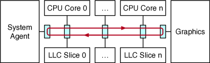
The ring interconnect, often referred to as ring bus, is a high-bandwidth on-die interconnect which was introduced by Intel with the Nehalem-EX micro-architecture [57] and is used on most Intel CPUs available in the market today [50]. Shown in Figure 1, it is used for intra-processor communication between the cores, the LLC, the system agent (previously known as Uncore) and the GPU. For example, when a core executes a load and it misses in its private caches (L1-L2), the load has to travel through the ring interconnect to reach the LLC and/or the memory controller. The different CPU consumers/producers communicating on the ring interconnect are called ring agents [53]. Each ring agent communicates with the ring through a ring stop (sometimes referred to as interface block [53], node router [12, 29], or ring station [87]). Every core shares its ring stop with one LLC slice. To minimize latency, traffic on the ring interconnect always uses the shortest path, meaning that ring stops can inject/receive traffic in both directions (right or left in our diagram) and always choose the direction with the shortest path to the destination. Finally, the communication protocol on the the ring interconnect makes use of four physical rings: request, snoop, acknowledge and data ring [60].
2.1 Microarchitectural Side Channels
Most microarchitectural channels can be classified using two criteria. First, according to the microarchitectural resource that they exploit. Second, based on the degree of concurrency (also referred to as leakage channel) that they rely on [34].111Other classifications exist, such as the historical one into storage or timing channels [1], but our classification is more useful for this paper.
Target Resource Type
We distinguish between eviction-based (also referred to as persistent- or residual-state) and contention-based (also known as transient state) attacks. Eviction-based channels are stateful: the adversary actively brings the microarchitectural resource into a known state, lets the victim execute, and then checks the state of the shared resource again to learn secrets about the victim’s execution. In these attacks, the side effects of the victim’s execution leave a footprint that is not undone when the victim code completes. The root cause of these attacks is the limited storage space of the shared microarchitectural resource. Examples of shared resources that can be used for eviction-based channels are the L1 data [81, 78, 63] and instruction [2, 115, 5] caches, the TLB [39], the branch target buffer (BTB) [26, 27] and the last-level cache (LLC) [65, 111, 51, 42, 116, 69, 41, 54, 22, 36, 88].
Contention-based channels are stateless: the adversary passively monitors the latency to access the shared resource and uses variations in this latency to infer secrets about the victim’s execution. In these attacks, the side effects of the victim’s execution are only visible while the victim is executing. The root cause of these attacks is the limited bandwidth capacity of the shared resource. Examples of resources that can be used for contention-based channels are functional units [105], execution ports [8, 16, 38], cache banks [113], the memory bus [108] and random number generators [25]. The attack presented in this paper is a contention-based channel.
Leakage Channel
We further classify attacks as either relying on preemptive scheduling, SMT or multicore techniques. Preemptive scheduling approaches [44, 27, 115, 73, 78, 11, 43, 18, 28, 103, 86, 2], also referred to as time-sliced approaches, consist of the victim and the attacker time-sharing a core. In these attacks, the victim and the attacker run on the same core and their execution is interleaved. Simultaneous multithreading (SMT) approaches [105, 63, 8, 4, 3, 78, 81, 39] rely on the victim and the attacker executing on the same core in parallel (concurrently). Multicore approaches [65, 111, 51, 42, 116, 69, 41, 54, 22, 25, 94, 110, 109] are the most generic with the victim and the attacker running on separate cores. The attack presented in this paper uses the multicore leakage channel.
2.2 Side Channel Defenses
Several defenses to microarchitectural side channels have been proposed. We focus here on generic approaches. The most straightforward approach to block a side channel is to disable the sharing of the microarchitectural component on which it relies. For example, attacks that rely on simultaneous multithreading (SMT) can be thwarted by disabling SMT, which is an increasingly common practice for both cloud providers and end users [67, 10, 19]. Other approaches propose to partition the shared resource to ensure that its use by the victim cannot be monitored by the attacker [92, 56, 64, 118, 104]. For example, Liu et al. [64] present a defense to multicore cache attacks that uses Intel CAT [74] to load sensitive victim cache lines in a secure LLC partition where they cannot be evicted by the attacker. Finally, for channels that rely on preemptive scheduling and SMT, one mitigation approach is to erase the victim’s footprint from the microarchitectural state across context switches. For example, several works proposed to flush the CPU caches on context switches [92, 37, 117, 99, 44, 78, 17, 35, 32, 34, 43, 81].
3 Reverse Engineering the Ring Interconnect
In this section, we set out to understand the microarchitectural characteristics of the ring interconnect on modern Intel CPUs, with a focus on the necessary and sufficient conditions for an adversary to create and monitor contention on it. This information will serve as the primitive for our covert channel (Section 4) and side channel attacks (Section 5).
Experimental Setup
We run our experiments on two machines. The first one uses an 8-core Intel Core i7-9700 (Coffee Lake) CPU at 3.00GHz. The second one uses a 4-core Intel Core i7-6700K (Skylake) CPU at 4.00GHz. Both CPUs have an inclusive, set-associative LLC. The LLC has 16 ways and 2048 sets per slice on the Skylake CPU and 12 ways and 2048 sets per slice on the Coffee Lake CPU. Both CPUs have an 8-way L1 with 64 sets and a 4-way L2 with 1024 sets. We use Ubuntu Server 16.04 with the kernel 4.15 for our experiments.
3.1 Inferring the Ring Topology
Monitoring the Ring Interconnect
We build on prior work [30] and create a monitoring program that measures, from each core, the access time to different LLC slices. Let , and be the associativities of the L1, L2 and LLC respectively. Given a core , an LLC slice index and an LLC cache set index , our program works as follows:
-
1.
It pins itself to the given CPU core .
-
2.
It allocates a buffer of MB of memory.222We found 400 MB to be enough to contain the addresses of Step 2.
-
3.
It iterates through the buffer looking for addresses that map to the desired slice and LLC cache set and stores them into the monitoring set. The slice mapping is computed using the approach from Maurice et al. [68], which uses hardware performance counters. This step requires root privileges, but we will discuss later how we can compute the slice mapping also with unprivileged access.
-
4.
It iterates through the buffer looking for addresses that map to the same L1 and L2 cache sets as the addresses of the monitoring set, but a different LLC cache set (i.e., where the LLC cache set index is not ) and stores them into a set which we call the eviction set.
-
5.
It performs a load of each address of the monitoring set. After this step, all the addresses of the monitoring set should hit in the LLC because their number is equal to . Some of them will hit in the private caches as well.
-
6.
It evicts the addresses of the monitoring set from the private caches by accessing the addresses of the eviction set. This trick is inspired by previous work [109] and ensures that the addresses of the monitoring set are cached in the LLC, but not in the private caches.
-
7.
It times loads from the addresses of the monitoring set one at a time using the timestamp counter (rdtsc) and records the measured latencies. These loads will miss in the private caches and hit in the LLC. Thus, they will need to travel through the ring interconnect. Steps 6-7 are repeated as needed to collect the desired number of latency samples.
Results
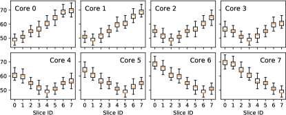
We run our monitoring program on each CPU core and collect 100,000 samples of the “load latency” from each different LLC slice. The results for our Coffee Lake CPU are plotted in Figure 2. The results for our Skylake CPU are shown in Appendix A.1. These results confirm that the logical topology of the ring interconnect on both our CPUs matches the linear topology shown in Figure 1. That is: 1. The LLC load latency is larger when the load has to travel longer distances on the ring interconnect.
Once this topology and the respective load latencies are known to the attacker, they will be able to map any addresses to their slice by just timing how long it takes to access them and comparing the latency with the results of Figure 2. As described so far, monitoring latency narrows down the possible slices from to 2. To pinpoint the exact slice a line maps to, the attacker can then triangulate from 2 cores. This does not require root access. Prior work explores how this knowledge can be used by attackers to reduce the cost of finding eviction sets and by defenders to increase the number of colors in page coloring [112, 41]. What else can an attacker do with this knowledge? We investigate this question in the next section.

3.2 Understanding Contention on the Ring
We now set out to answer the question: under what circumstances can two processes contend on the ring interconnect? To this end, we reverse engineer Intel’s “sophisticated ring protocol” [90, 60] that handles communication on the ring interconnect. We use two processes, a receiver and a sender.
Measuring Contention
The receiver is an optimized version of the monitoring program described in Section 3.1, that skips Steps 4 and 6 (i.e., does not use an eviction set) thanks to the following observation: since on our CPUs and , not all the addresses of the monitoring set can fit in the L1 and L2 at any given time. For example, on our Skylake machine, and . Consider the scenario when we access the first 4 addresses of our monitoring set. These addresses fit in both the private caches and the LLC. However, we observe that accessing one by one the remaining 12 addresses of the monitoring set evicts the first 4 addresses from the private caches. Hence, when we load the first addresses again at the next iteration, we still only hit in the LLC. Using this trick, if we loop through the monitoring set and access its addresses in order, we can always load from the LLC. To ensure that the addresses are accessed in order, we serialize the loads using pointer chasing, which is a technique also used in prior work [97, 65, 39, 103]. Further, to make it less likely to suffer LLC evictions due to external noise, our receiver evenly distributes the addresses of the monitoring set across two LLC cache sets (within the same slice). Finally, to amplify the contention signal, our receiver times 4 sequential loads at a time instead of 1. The bulk of our receiver’s code is shown in Listing 9 (in Appendix A).
Creating Contention
The sender is designed to create contention on specific segments on the ring interconnect by “bombarding” it with traffic. This traffic is sent from its core to different CPU components which sit on the ring, such as LLC slices and the system agent. To target a specific LLC slice, our sender is based on the same code as the receiver. However, it does not time nor serialize its loads. Further, to generate more traffic, it uses a larger monitoring set with addresses (evenly distributed across two LLC cache sets). To target the system agent (SA), our sender uses an even larger monitoring set with addresses. Because not all these addresses will fit in two LLC cache sets, these loads will miss in the cache, causing the sender to communicate with the memory controller (in the SA).
Data Collection
We use the receiver and the sender to collect data about ring contention. For the first set of experiments, we configure the sender to continuously load data from a single LLC slice (without LLC misses). For the second set of experiments, we configure the sender to always incur misses on its loads from the target LLC slice. To prevent unintended additional noise, we disable the prefetchers and configure the sender and the receiver to target different cache sets so that they do not interfere through traditional eviction-based attacks. We refer to the sender’s core as , the slice it targets as , the receiver’s core as and the slice it targets as . For both core and slice numbering, we follow the diagram of Figure 1. For every combination of , , and , we test if running the sender and the receiver concurrently affects the load latency measured by the receiver. We then compare the results with a baseline, where the sender is disabled. We say that there is contention when the average load latency measured by the receiver is larger than the baseline. Figure 3 shows the results of our first experiment, when the sender always hits in the LLC. Figure 13 (in Appendix A.1) shows the results of our second experiment, when the sender always misses in the LLC. Both figures refer to our Coffee Lake machine. The results of our 4-core Skylake machine are a subset of the 8-core Coffee Lake ones (with ).
Observations When the Sender Hits in the LLC
First, there is always contention when , irrespective of the sender’s and the receiver’s positions relative to the LLC slice. This systematic “slice contention” behavior is marked with a in Figure 3, and is likely caused by a combination of i) the sender’s and the receiver’s loads filling up the slice’s request queue (whose existence is mentioned by Intel in [80]), thus causing delays to the processing time of the load requests and ii) the sender’s and receiver’s loads saturating the bandwidth of the shared slice port (which can supply at most 32 B/cycle [50], or half a cache line per cycle), thus causing delays to the sending of the cache lines back to the cores. 2. When an agent bombards an LLC slice with requests, other agents loading from the same slice observe delays.
Second, when , there is contention iff . That is, receiver’s loads from to (core to home slice traffic) never contend with sender’s loads from to (cross-ring traffic). This confirms that every core has a “home” slice that occupies no links on the ring interconnect except for the shared core/slice ring stop [53]. 3. A ring stop can service core to home slice traffic and cross-ring traffic simultaneously.
Third, excluding slice contention (), there is never contention if the sender and the receiver perform loads in opposite directions. For example, there is no contention if the receiver’s loads travel from “left” to “right” () and the sender’s ones from “right” to “left” (), or vice versa. The fact that loads in the right/left direction do not contend with loads in the left/right direction confirms that the ring has two physical flows, one for each direction (as per Figure 1). This observation is supported by Intel in [60]. 4. A ring stop can service cross-ring traffic traveling on opposite directions simultaneously.
Fourth, even when the sender and receiver’s loads travel in the same direction, there is never contention if the ring interconnect segments between and and between and do not overlap. For example, when and , there is no contention if and or if and . This is because load traffic on the ring interconnect only travels through the shortest path between the ring stop of the core and the ring stop of the slice. If the sender’s segment does not overlap with the receiver’s segment, the receiver will be able to use the full bus bandwidth on its segment. 5. Ring traffic traveling through non-overlapping segments of the ring interconnect does not cause contention.
The above observations narrow us down to the cases when the sender and the receiver perform loads in the same direction and through overlapping segments of the ring. Before we analyze these cases, recall from Section 2 that the ring interconnect consists of four rings: 1) request, 2) acknowledge, 3) snoop and 4) data rings. While it is fairly well known that 64 B cache lines are transferred as two packets over the 32 B data ring [72, 53, 107], little is disclosed about i) what types of packets travel through the other three rings and ii) how packets flow through the four rings during a load transaction. Intel partially answers (i) in [80] and [49] where it explains that the separate rings are respectively used for 1) read/write requests 2) global observation333Global observations are also known as completion messages [95]. and response messages, 3) snoops to the cores444 Snoops are related to cache coherence. For example, when multiple cores share a cache line in the LLC, the shared LLC can send snoop packets to cores to maintain coherency across copies. Because our sender and receiver do not share any data, their loads should not need to use the snoop ring. and 4) data fills and write-backs. Further, Intel sheds lights on (ii) in an illustration from [60] which explains the flow of an LLC hit transaction: the transaction starts with a request packet that travels from the core to the target LLC slice555Cores use a fixed function to map addresses to slices [107, 68, 60]. (hit flow 1: coreslice, request); upon receipt of such packet, the slice retrieves the requested cache line; finally, it sends back to the core a global observation (GO) message followed by the two data packets of the cache line (hit flow 2: slicecore, data and acknowledge). 6. The ring interconnect is divided into four independent and functionally separated rings. A clean LLC load uses the request ring, the acknowledge ring and the data ring.
Importantly, however, our data shows that performing loads in the same direction and sharing a segment of the ring interconnect with the receiver is not a sufficient condition for the sender to create contention on the ring interconnect.
First, the receiver does not see any contention if its traffic envelops the sender’s traffic of the ring interconnect (i.e., or ). For example, when and , we see no contention if and . This behavior is due to the distributed arbitration policy on the ring interconnect. Intel explains it with an analogy, comparing the ring to a train going along with cargo where each ring slot is analogous to a boxcar without cargo [72]. To inject a new packet on the ring, a ring agent needs to wait for a free boxcar. This policy ensures that traffic on the ring is never blocked but it may delay the injection of new traffic by other agents, because packets already on the ring have priority over new packets.666This arbitration policy has been previously described also in [12, 45, 29]. To create contention on a ring, the sender thus needs to inject its traffic into that ring so that it has priority over the receiver’s traffic, which can only happen if its packets are injected at stops upstream from the receiver’s ones. 7. A ring stop always prioritizes traffic that is already on the ring over new traffic entering from its agents. Ring contention occurs when existing on-ring traffic delays the injection of new ring traffic.
Second, even when the sender’s traffic is prioritized over the receiver’s traffic, the receiver does not always observe contention. Let cluster and . When the sender has priority on the request ring (on the coreslice traffic), there is contention if is in the same cluster as . Similarly, when the sender has priority on the data/acknowledge rings (on the slicecore traffic), there is contention if is in the same cluster as . If the sender has priority on all rings, we observe the union of the above conditions. This observation suggests that each ring may have two “lanes”, and that ring stops inject traffic into different lanes depending on the cluster of its destination agent. As an example for the slicecore traffic, let () and . In this case, traffic from to travels on the lane corresponding to core cluster B. When () and , traffic from to travels on the lane corresponding to core cluster A. The two traffic flows thus do not contend. However, if we change to (), the traffic from to also travels on the lane corresponding to core cluster B, thus contending with the receiver. 8. Each ring has two lanes. Traffic destined to slices in travels on one lane, and traffic destined to slices in travels on the other lane. Similarly, traffic destined to cores in travels on one lane, and traffic destined to cores in travels on the other lane.
Finally, we observe that the amount of contention that the sender causes when it has priority only on the slicecore traffic is larger than the amount of contention that it causes when it has priority only on the coreslice traffic. This is because i) slicecore consists of both acknowledge ring and data ring traffic, delaying the receiver on two rings, while coreslice traffic only delays the receiver on one ring (the request ring) and ii) slicecore data traffic itself consists of 2 packets per load which occupy more slots (“boxcars”) on its ring, while request traffic likely consists of 1 packet, occupying only one slot on its ring. Furthermore, the amount of contention is greatest when the sender has priority over both slicecore and coreslice traffic. 9. Traffic on the data ring creates more contention than traffic on the request ring. Further, contention is larger when traffic contends on multiple rings simultaneously.
Putting this all together, Figure 3 contains two types of contention: slice contention (cells with a ) and ring interconnect contention (gray cells). The latter occurs when the sender’s request traffic delays the injection of the receiver’s request traffic onto the request ring, or the sender’s data/GO traffic delays the injection of the receiver’s data/GO traffic onto the data/acknowledge rings. For this to happen, the sender’s traffic needs to travel on the same lane, on overlapping segments, and in the same direction as the receiver’s traffic, and must be injected upstream from the receiver’s traffic. Formally, when the sender hits in the LLC cache, contention happens iff:
| (1) | ||||
Observations When the Sender Misses in the LLC
We now report our observations on the results of our second experiment (shown in Figure 13), when the sender misses in the LLC. Note that the receiver’s loads still hit in the LLC.
First, we still observe the same slice contention behavior that we observed when the sender hits in the LLC. This is because, even when the requested cache line is not present in , load requests still need to travel from to first [50] and thus still contribute to filling up the LLC slice’s request queue creating delays [80]. Additionally, the sender’s requests (miss flow 1: coreslice, request) still contend with the receiver’s coreslice request traffic when , , and meet the previous conditions for request ring contention. 10. Load requests that cannot be satisfied by the LLC still travel through their target LLC slice.
Second, Intel notes that in the event of a cache miss, the LLC slice forwards the request to the system agent (SA) over the same request ring (same request ring lane in our terminology) from which the request arrived [80]. That is, LLC miss transactions include a second request flow from to the SA (miss flow 2: sliceSA, request). Our data supports the existence of this flow. We observe contention when the receiver’s loads travel from right to left (), , and the sender and the receiver share the respective lane ( is in the same cluster as ). For example, when , () and () the sender’s requests from to the SA contend with the receiver’s requests from to . One subtle implication of this fact is that the SA behaves differently than the other ring agent types (slices and cores) in that it can receive request traffic on either lane of the request ring. We find that simply forwards the request (as new traffic) to the SA on the same lane on which it received it from , subject to the usual arbitration rules.
We make two additional observations: i) The amount of contention caused by the sliceSA flow is smaller than the one caused by the coreslice flow. We do not have a hypothesis for why this is the case. ii) In the special case ( in our example) there is slightly less contention than in the cases where . This may be because, when asked to inject new traffic by both its core and its slice, the ring stop adopts a round-robin policy rather than prioritizing either party. Intel uses such a protocol in a recent patent [79]. 11. In case of a miss, an LLC slice forwards the request (as new traffic) to the system agent on the same lane in which it arrived. When both a slice and its home core are trying to inject request traffic into the same lane, their ring stop adopts a fair, round-robin arbitration policy.
To our knowledge, no complete information has been disclosed on the subsequent steps of an LLC miss transaction. We report here our informed hypothesis. In addition to forwarding the request to the SA, slice also responds to the requesting core with a response packet through the acknowledge ring (miss flow 3: slicecore, acknowledge). After receiving the request from , the SA retrieves the data and sends it to the requesting core preceded by a GO message (miss flow 4: SAcore, data and acknowledge). The transaction completes when receives the requested data.
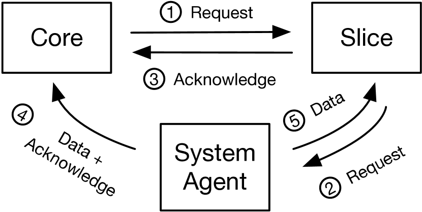
To maintain inclusivity, the SA also sends a separate copy of the data to through the data ring (miss flow 5: SAslice, data). We summarize the five flows discussed in this part in Figure 4.
The existence of miss flow 4 (SAcore, data/acknowledge) is supported by the presence of contention when the receiver’s loads travel from right to left (), with , and share the respective data/acknowledge ring lanes with the sender. For example, there is contention when (), , () and . Recall from Figure 1 that the SA sits on the leftmost ring stop, which implies that traffic injected by the SA always has priority over the receiver’s traffic injected by . To corroborate our hypothesis that the SA serves data/acknowledge traffic directly to (and not through ), we time the load latency of a single LLC miss of the sender with varying and fixed . If our hypothesis held, we would expect a constant latency, because regardless of the transaction would need to travel from to ring stop 7, from ring stop 7 to the SA, and from the SA to , which is the same distance regardless of ; otherwise we would expect to see a decreasing latency as increases. We measure a fixed latency ( cycles), confirming our hypothesis. 12. The system agent supplies data and global observation messages directly to the core that issued the load.
The existence of miss flow 3 (slicecore, acknowledge) is supported by the presence of contention in the cases where we previously observed data/acknowledge ring contention with a sender that hits in the LLC. For example, we observe contention when (), , () and . However, when the sender misses in the LLC, no data traffic is sent by to (since we saw that data is served to the core directly by the SA). The contention we observe must then be due to injecting traffic into the acknowledge ring. Indeed, the amount of contention caused by this acknowledge-only flow is both smaller than the one caused by data/acknowledge flows and equivalent to the one caused by the coreslice request flow, suggesting that, similarly to the request flow, miss flow 3 may occupy a single slot on its ring. An Intel patent suggests that miss flow 3 may consist of an “LLCMiss” message transmitted by to when the request misses in the LLC [100]. The only remaining question (which we currently cannot answer) is when miss flow 3 occurs: when the miss is detected or when the data is refilled—but both options would cause the same contention. 13. In the event of a miss, the LLC slice that misses still sends a response packet through the acknowledge ring back to the requesting core.
Finally, the existence of miss flow 5 (SAslice, data) is supported by the presence of contention when the receiver’s loads travel from right to left (), with , and share the respective lane with the sender. However, we find a subtle difference in the contention rules of the SAslice traffic. Unlike the SAcore case, where receiver and sender contend due to traffic of the same type (data and acknowledge) being destined to agents of the same type (cores), we now have receiver’s and sender’s flows of the same type (data) destined to agents of different types (cores and slices, respectively). In the former case, we saw that the receiver flow and the sender flow share the lane if their destination ring agents are in the same cluster. In the latter case (which occurs only in this scenario), we observe that the two flows share the lane if their destination ring agents are in different clusters. This suggests that, as we summarize in Table 1, the lanes used to communicate to different clusters may be flipped depending on the destination agent type. We make two additional observations about miss flow 5. First, we believe that the SAslice traffic only includes data and no acknowledge traffic because the amount of contention that it causes is slightly smaller than the one caused by the SAcore traffic. Second, we find that the SAslice traffic occurs separately from the SAcore traffic. For example, the contention we observe when (), , , () could not occur if the data from the SA had to stop by first. Also, when the sender contends both on the SAslice and SAcore traffic the contention is larger than the individual contentions, which further supports the independence of the two flows. 14. In the event of a miss, the system agent supplies a separate copy of the data to the missing LLC slice, in order to maintain inclusivity. The ring lane used to send data traffic to an LLC slice of one cluster is the same used to send data traffic to a core of the opposite cluster.
| Destination Ring Agent Type | Destination Ring Agent Cluster | |
| Core | Lane 1 | Lane 2 |
| LLC Slice | Lane 2 | Lane 1 |
To sum up, when the sender misses in the LLC, new ring contention cases occur compared to Equation 1 due to the extra flows required to handle an LLC miss transaction. Formally, contention happens iff:
| (2) | ||||
Additional Considerations
We now provide additional observations on our results. First, the amount of contention is not proportional to length of the overlapping segment between the sender and the receiver. This is because, as we saw, contention depends on the presence of full “boxcars” passing by the receiver’s ring stops when they are trying to inject new traffic, and not on how far away the destination of these boxcars is.
Second, the amount of contention grows when multiple senders contend with the receiver’s traffic simultaneously. This is because multiple senders fill up more slots on the ring, further delaying the receiver’s ring stops from injecting their traffic. For example, when and , running one sender with and and one with and creates more contention than running either sender alone.
Third, enabling the hardware prefetchers both amplifies contention in some cases, and causes contention in some new cases (with senders that would not contend with the receiver if the prefetchers were off). This is because prefetchers cause the LLC or the SA to transfer additional cache lines to the core (possibly mapped to other LLC slices than the one of the requested line), thus filling up more ring slots potentially on multiple lanes. Intel itself notes that prefetchers can interfere with normal loads and increase load latency [48]. We leave formally modeling the additional contention patterns caused by the prefetchers for future work.
Finally, we stress that the contention model we constructed is purely based on our observations and hypotheses from the data we collected on our CPUs. It is possible that some of the explanations we provided are incorrect. However, our primary goal is for our model to be useful, and in the next few sections we will demonstrate that it is useful enough to build attacks.
Security Implications
The results we present bring with them some important takeaways. First, they suggest an affirmative answer to our question on whether the ring interconnect is susceptible to contention. Second, they teach us what type of information a receiver process monitoring contention on the ring interconnect can learn about a separate sender process running on the same host. By pinning itself to different cores and loading from different slices, a receiver may distinguish between the cases when the sender is idle and when it is executing loads that miss in its private caches and are served by a particular LLC slice. Learning what LLC slice another process is loading from may also reveal some information about the physical address of a load, since the LLC slice an address maps to is a function of its physical address [107, 68, 60]. Further, although we only considered these scenarios, ring contention may be used to distinguish other types on sender behavior, such as communication between the cores and other CPU components (e.g., the graphics unit and the peripherals). Importantly, however, for any of these tasks the receiver would need to set itself up so that contention with the sender is expected to occur. Equations 1 and 2 make this possible by revealing the necessary and sufficient conditions under which traffic can contend on the ring interconnect.
4 Cross-core Covert Channel
We use the findings of Section 3 to build the first cross-core covert channel to exploit contention on the ring interconnect. Our covert channel protocol resembles conventional cache-based covert channels (e.g., [65, 109]), but in our case the sender and the receiver do not need to share the cache. The basic idea of the sender is to transmit a bit “1” by creating contention on the ring interconnect and a bit “0” by idling, thus creating no ring contention. Simultaneously, the receiver times loads (using the code of Listing 9) that travel through a segment of the ring interconnect susceptible to contention due to the sender’s loads (this step requires using our results from Section 3). Therefore, when the sender is sending a “1”, the receiver experiences delays in its load latency. To distinguish a “0” from a “1” the receiver can then simply use the mean load latency: smaller load latencies are assigned to a “0”, and larger load latencies are assigned to a “1”. To synchronize sender and receiver we use the shared timestamp counter, but our channel could also be extended to use other techniques that do not rely on a common clock (e.g., [83, 70, 108, 46]).
To make the covert channel fast, we leverage insights from Section 3. First, we configure the receiver to use a short segment of the ring interconnect. This allows the receiver to issue more loads per unit time due to the smaller load latency, without affecting the sender’s ability to create contention. Second, we set up the sender to hit in the LLC and use a configuration of and where, based on Equation 1, it is guaranteed to contend with the receiver both on its coreslice traffic and on its slicecore one. Contending on both flows allows the sender to amplify the difference between a 0 (no contention) and a 1 (contention). Third, we leave the prefetchers on, as we saw that they enable the sender to create more contention.
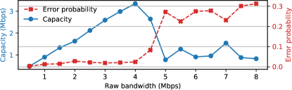
We create a proof-of-concept implementation of our covert channel, where the sender and the receiver are single-threaded and agree on a fixed bit transmission interval. Figure 5 shows the load latency measured by the receiver on our Coffee Lake 3.00 GHz CPU, given receiver and sender configurations , and , , respectively. For this experiment, the sender transmits a sequence of alternating ones and zeros with a transmission interval of 3,000 cycles (equivalent to a raw bandwidth of 1 Mbps). The results show that ones (hills) and zeros (valleys) are clearly distinguishable. To evaluate the performance and robustness of our implementation with varying transmission intervals, we use the channel capacity metric (as in [83, 75]). This metric is computed by multiplying the raw bandwidth with , where is the probability of a bit error and is the binary entropy function. Figure 6 shows the results on our Coffee Lake CPU, with a channel capacity that peaks at 3.35 Mbps (418 KBps) given a transmission interval of 750 cycles (equivalent to a raw bandwidth of 4 Mbps). To our knowledge, this is the largest covert channel capacity of all existing cross-core covert channels that do not rely on shared memory to date (e.g., [83, 108]). We achieve an even higher capacity of 4.14 Mbps (518 KBps) on our Skylake 4.00 GHz CPU by using a transmission interval of 727 cycles, and show the results in Appendix A.2.
Finally, we remark that while our numbers represent a real, reproducible end-to-end capacity, they were collected in the absence of background noise. Noisy environments may reduce the covert channel performance and require including in the transmission additional error correction codes (as in, e.g., [25, 70, 41]), that we do not take into account.
5 Cross-core Side Channels
In this section, we present two examples of side channel attacks that exploit contention on the ring interconnect.
Basic Idea
In both our attacks, we implement the attacker using the technique described in Section 3 (cf. Listing 9). The attacker (receiver) issues loads that travel over a fixed segment of the ring interconnect and measures their latency. We will refer to each measured load latency as a sample, and to a collection of many samples (i.e., one run of the attacker/receiver) as a trace. If during an attack the victim (sender) performs memory accesses that satisfy the conditions of Equations 1 and 2 to contend with the attacker’s loads, the attacker will measure longer load latencies. Generally, the slices accessed by an unwitting victim will be uniformly distributed across the LLC [50]. Therefore, it is likely that some of the victim’s accesses will contend with the attacker’s loads. If the delays measured by the attacker can be attributed to a victim’s secret, the attacker can use them as a side channel.
Threat Model and Assumptions
We assume that SMT is off [67, 10, 19] and that multicore cache-based attacks are not possible (e.g., due to partitioning the LLC [74, 64, 92] and disabling shared memory across security domains [118, 102]). For our attack on cryptographic code, we also assume that i) the administrator has configured the system to cleanse the victim’s cache footprint on context switches (to block cache-based preemptive scheduling attacks [92, 37, 117, 99, 34, 44, 17, 78, 43, 35, 32, 81]) and ii) the attacker can observe multiple runs of the victim. We assume an attacker who has knowledge of the contention model (Section 3) for the victim’s machine and can run unprivileged code on the victim’s machine itself.
5.1 Side Channel Attack On Cryptographic Code
Our first attack targets a victim that follows the pseudocode of Algorithm 1, where E1 and E2 are separate functions executing different operations on some user input (e.g., a ciphertext). This is a common pattern in efficient implementations of cryptographic primitives that is exploited in many existing side channel attacks against, e.g., RSA [81, 111, 38, 109], ElGamal [65, 115], DSA [82], ECDSA [15] and EdDSA [39, 38].
Let us consider the first iteration of the victim’s loop, and, for now, assume that the victim starts from a cold cache, meaning that its code and data are uncached (no prior executions). When the victim executes E1 for the first time, it has to load code and data words used by E1 into its private caches, through the ring interconnect. Then, there are 2 cases: when the first key bit is 0 and when it is 1. When the first bit is , the victim’s code skips the call to E2 after E1 and jumps to the next loop iteration by calling E1 again. At this second E1 call, the words of E1 are already in the private caches of the victim, since they were just accessed. Therefore, the victim does not send traffic onto the ring interconnect during the second call to E1. In contrast, when the first bit is , the victim’s code calls E2 immediately after the first E1. When E2 is called for the first time, its code and data words miss in the cache and loading them needs to use the ring interconnect. The attacker can then infer whether the first bit was or by detecting whether E2 executed after E1. Contention peaks following E1’s execution imply that E2 executed and that the first secret bit was , while no contention peaks following E1’s execution imply that the call to E1 was followed by another call to E1 and that the first secret bit was .
We can generalize this approach to leaking multiple key bits by having the attacker interrupt/resume the victim using preemptive scheduling techniques [44, 115, 73, 78, 11, 43, 18, 28, 103, 27, 2, 86]. Let be the median time that the victim takes to execute E1 starting from a cold cache and be the median time that the victim takes to execute E1 followed by E2 starting from a cold cache. The complete attack works as follows: the attacker starts the victim and lets it run for cycles while concurrently monitoring the ring interconnect. After cycles, the attacker interrupts the victim and analyzes the collected trace to infer the first secret bit with the technique described above. Interrupting the victim causes a context switch during which the victim’s cache is cleansed before yielding control to the attacker (cf. Threat Model). As a side effect, this brings the victim back to a cold cache state. If the trace reveals that the first secret bit was 1, the attacker resumes the victim (that is now at the beginning of the second iteration) and lets it run for more cycles, repeating the above procedure to leak the second bit. If the trace reveals that the first secret bit was 0, the attacker stops the victim (or it lets it finish the current run), starts it again from the beginning, lets it run for cycles, and then interrupts it. The victim will now be at the beginning of the second iteration, and the attacker can repeat the above procedure to leak the second bit. The attacker repeats this operation until all the key bits are leaked. In the worst case, if all the key bits are zeros, our attack requires as many runs of the victim as the number of bits of the key. In the best case, if all the key bits are ones, it requires only one run of the victim.
Implementation
We implement a proof-of-concept (POC) of our attack against RSA and EdDSA. Like prior work [43, 18, 28, 103, 27, 2, 5], our POC simulates the preemptive scheduling attack by allowing the attacker to be synchronized with the target iteration of the victim’s loop.777 Practical implementations of preemptive scheduling techniques (e.g., [44, 86, 11, 73]) are orthogonal to this paper and discussed in Section 6. Further, our POC simulates cache cleansing by flushing the victim’s memory before executing the target iteration. It does this by calling clflush on each cache line making up the victim’s mapped pages (available in /proc/[pid]/maps).888 We consider other cache cleansing approaches in Appendix A.3, and discuss the implications of this requirement in Section 6. Our POC considers the worst-case scenario described above and leaks one key bit per run of the victim. To simplify the process of inferring a key bit from each resulting trace, our POC uses a Support Vector Machine classifier (SVC). Note that while the RSA and EdDSA implementations we consider are already known to be vulnerable to side channels, we are the first to show that they leak over the ring interconnect channel specifically.
Results for RSA
We target the RSA decryption code of libgcrypt 1.5.2 which uses the secret-dependent square-and-multiply method in its modular exponentiation function _gcry_mpi_powm. This pattern matches the one of Algorithm 1, with E1 representing the squaring phase, executed unconditionally, and E2 representing the multiplication phase, executed conditionally only on 1-valued bits of the key.
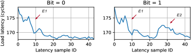
We configure the attacker (receiver) on core , timing loads from , and experiment with different victim (sender) cores . Figure 10 shows traces collected by the attacker to leak one key bit of the victim, when . To better visualize the difference between a 0 bit and a 1 bit, the traces are averaged over 100 runs of the victim.131313Note that, however, our classifier uses a single raw trace as input. As expected, we observe that both traces start with peaks, corresponding to the first call to E1 loading its code and data words from the memory controller through the ring interconnect. However, only when the secret bit is 1 do we observe an additional peak on the right-hand side of the plot. This additional peak corresponds to the call to E2. We get equally distinguishable patterns when we run the victim on other cores, as well as on our Skylake machine (cf. Appendix A.3).
To train our classifier, we collect a set of 5000 traces, half of which with the victim operating on a 0 bit and the other half with it operating on a 1 bit. We use the first 43 samples from each trace as input vectors, and the respective 0 or 1 bits as labels. We then randomly split the set of vectors into 75% training set and 25% testing set, and train our classifier to distinguish between the two classes. Our classifier achieves an accuracy of 90% with prefetchers on and 86% with prefetchers off, demonstrating that a single trace of load latencies measured by the attacker during a victim’s iteration can leak that iteration’s secret key bit with high accuracy.
Results for EdDSA
We target the EdDSA Curve25519 signing code of libgcrypt 1.6.3, which includes a secret-dependent code path in its elliptic curve point-scalar multiplication function _gcry_mpi_ec_mul_point. In this function, the doubling phase represents E1, executed unconditionally, and the addition phase represents E2, executed conditionally only on 1-valued bits of the key (i.e., the scalar).
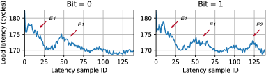
We report in Figure 12 the results of leaking a bit using the same setup as in the RSA attack. Both traces start with peaks corresponding to the first call to E1. However, only when the secret bit is 1 do we observe an additional peak on the right-hand side of the plot. This additional peak corresponds to the call to E2. We get similar patterns with the victim on other cores, as well as on our Skylake machine (cf. Appendix A.3). We train our classifier like we did for the RSA attack, except that the individual vectors now contain 140 samples. Our classifier achieves an accuracy of 94% with prefetchers on and 90% with prefetchers off.
5.2 Keystroke Timing Attacks
Our second side channel attack leaks the timing of keystrokes typed by a user. That is, like prior work [85, 52, 61, 59, 114, 83, 41, 101], the goal of the attacker is to detect when keystrokes occur and extract precise inter-keystroke timings. This information is sensitive because it can be used to reconstruct typed words (e.g., passwords) [114, 91, 59]. To our knowledge, this is the first time a contention-based microarchitectural channel (cf. Section 2.1) has been used for keystroke timing attacks.
Our attack builds on the observation that handling a keystroke is an involved process that requires interaction of multiple layers of the hardware and software stack, including the southbridge, various CPU components, kernel drivers, character devices, shared libraries, and user space processes [31, 84, 9, 55, 88, 71]. Prior work has shown that terminal emulators alone incur keystroke processing latencies that are in the order of milliseconds [14, 66] (i.e., millions of cycles). Moreover, handling even a single keystroke involves executing and accessing large amounts of code and data [88]. Thus, we hypothesize that, on an otherwise idle server, keystroke processing may cause detectable peaks in ring contention.
Implementation
To validate our hypothesis, we develop a simple console application that calls getchar() in a loop and records the time when each key press occurs, to serve as the ground truth (as in [114]). We consider two scenarios: i) typing on a local terminal (with physical keyboard input [31, 84]), and ii) typing over an interactive SSH session (with remote input [55, 13]).
Results
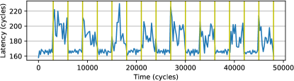
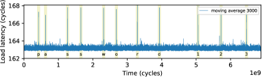
Figure 8 shows a trace collected by the attacker on our Coffee Lake machine in the SSH typing scenario, after applying a moving average with a window of 3000 samples. We report a zoomed-in version of the trace for a single keystroke in Figure 16(a). Our first observation is that when a keystroke occurs, we observe a very distinguishable pattern of ring contention. Running our attack while typing the first 100 characters of the “To be, or not to be” soliloquy, we observed this pattern upon all keystroke events with zero false negatives and zero false positives. Further, ring contention peaks were always observed well within 1 ms ( cycles) of recording a keystroke, which is the precision required by the inference algorithms used by prior work to differentiate the keys pressed. We got similar results when we typed keystrokes on a local terminal as well as on our Skylake machine (cf. Appendix A.3). Moreover, we tested our attack while running stress -m N in the background, which spawns N threads generating synthetic memory load on the system. The results, reported in Appendix A.3, show that the temporal patterns of ring contention on keystrokes were still easily distinguishable from background noise when . However, as the load increased (with ), keystrokes started to become harder to identify by simply using the moving average of Figure 8, and with , they started to become almost entirely indistinguishable from background noise.
We believe that the latency peaks we observe on keystrokes are caused by ring contention (and not, e.g., cache evictions or interrupts) for several reasons. First, the latency differences caused by contention on keystrokes are in the same range of the ones we measured in Section 3. Second, we observed that, although keystroke processing creates contention on all slices, latency peaks are more pronounced when the attacker monitors ring segments that incur more contention (i.e., the tables with the most gray cells in Figures 3 and 13). For example, when and the peaks upon keystrokes are smaller than in most other configurations. This is because in this configuration the attacker always has priority on both the request ring (there is no core upstream of whose request traffic can delay ’s one) and the data/acknowledge rings (there is no slice/SA upstream of whose data/acknowledge traffic can delay ’s one). Hence, we believe the only contention that occurs in this case is slice contention. Third, when we tried to repeat our experiments with the attacker timing L1 hits instead of LLC hits, we did not see latency peaks upon keystrokes.
6 Discussion and Future Work
Attack Requirements
Our attack on cryptographic code (cf. Section 5.1) requires the victim’s cache to be cleansed on context switches. On the one hand, this requirement limits the applicability of the attack, considering that cache cleansing is not currently done by major OSs. On the other hand, however, cache cleansing is often recommended [92, 37, 117, 99, 34, 44, 17, 78, 43, 35, 32, 81] as a defense against cache-based preemptive scheduling attacks, and may be deployed in the future if temporal isolation starts getting added to OSs. If so, defenders would be in a lose-lose situation: either they i) do not cleanse and get attacked through preemptive scheduling attacks or ii) cleanse and get attacked through our attack. These results highlight that side channel mitigations still need more study.
Moreover, our attack POC assumes (like prior work [78, 43, 18, 28, 103, 27, 2, 5]) the availability of preemptive scheduling techniques. A real attack, however, would include an implementation of such techniques. High-precision variants of these have been demonstrated for non-virtualized settings in [44, 86, 11, 73], and shown to be practical in virtualized settings in [115].141414 These techniques exploit the designs of the Linux/Xen CPU schedulers. The attacker spawns multiple threads, some of which run on the same CPU as the victim. The threads running on the victim’s CPU sleep most of the time. However, at carefully chosen times the attacker wakes them up, causing the scheduler to interrupt the victim to run the attacker. Preemptive scheduling is also practical against trusted execution environments such as Intel SGX [98]. Yet, future work is needed to assess the practicality of preemptive scheduling in more restricted environments such as browsers.
Mitigations
Intel classifies our attack as a “traditional side channel” because it takes advantage of architecturally committed operations [47]. The recommended line of defense against this class of attacks is to rely on software mitigations, and particularly on following constant-time programming principles. The attacks we demonstrate on RSA and EdDSA rely on code that is not constant time; in principle, this mitigation should be effective in blocking them. However, a more comprehensive understanding of hardware optimizations is needed before we can have truly constant-time code. For example, it was recently reported that Intel CPUs perform hardware store elimination between the private caches and ring interconnect [24]. This optimization may break constant-time programming by making ring contention a function of cache line contents.
Further, additional mitigations are needed to block our covert channel and our keystroke timing attack. Among hardware-only mitigations, designs based on spatial partitioning and statically-scheduled arbitration policies (e.g., [106]) could ensure that no ring contention can occur between processes from different security domains. However, they would need additional mechanisms to mitigate slice contention. Alternatively, less invasive hardware-software co-designs could be studied that allow “trusted” and “untrusted” code to only run on cores of different clusters (cf. Table 1), and only access slices of different clusters. However, such approaches would require careful consideration to account for LLC misses, which may create traffic that crosses clusters.
Finally, since our attacks rely on a receiver constantly missing in its private caches and performing loads from a target LLC slice, it may be possible to develop software-only anomaly detection techniques that use hardware performance counters to monitor bursts of load requests traveling to a single LLC slice. However, these techniques would only be useful if they had small false positive rates.
Applicability to Other CPUs
It should be possible to port our attacks on other CPUs using a ring interconnect. For example, we were able to replicate our methodology on a server-class Xeon Broadwell CPU, finding that the distributed (“boxcar”-based) arbitration policy is the same that we observed on our client-class CPUs (more details are in Appendix A.4). An open question is whether our attacks can be generalized to CPUs that do not use a ring interconnect. For example, recent server-class Intel CPUs utilize mesh interconnects [58], which consist of a 2-dimensional array of half rings. Traffic on this grid-like structure is always routed vertically first and then horizontally. More wires may make it harder for an attacker to contend with a victim. At the same time, however, they may provide the attacker with more fine-grained visibility onto what segments a victim is using, but this topic merits further investigation. Finally, AMD CPUs utilize other proprietary technologies known as Infinity Fabric/Architecture for their on-chip interconnect [96, 20]. Investigating the feasibility of our attack on these platforms requires future work. However, the techniques we use to build our contention model can be applied on these platforms too.
7 Conclusion
In this paper, we introduced side channel attacks on the ring interconnect. We reverse engineered the ring interconnect’s protocols to reveal the conditions for two processes to incur ring contention. We used these findings to build a covert channel with a capacity of over 4 Mbps, the largest to date for cross-core channels not relying on shared memory. We also showed that the temporal trends of ring contention can be used to leak key bits from vulnerable EdDSA/RSA implementations as well as the timing of keystrokes typed by a user. We have disclosed our results to Intel.
Acknowledgments
This work was partially supported by NSF grants 1954521 and 1942888 as well as by an Intel ISRA center. We thank our shepherd Yossi Oren and the anonymous reviewers for their valuable feedback. We also thank Gang Wang for his valuable suggestions on early drafts of this paper, and Ben Gras for the helpful discussions on the first side channel POC.
Availability
We have open sourced the code of all the experiments of this paper at https://github.com/FPSG-UIUC/lotr.
References
- [1] DoD 5200.28-STD. Department of Defense Trusted Computer System Evaluation Criteria, 1985.
- [2] Onur Aciiçmez. Yet another microarchitectural attack: Exploiting i-cache. In CSAW, 2007.
- [3] Onur Acıiçmez, Çetin Kaya Koç, and Jean-Pierre Seifert. On the power of simple branch prediction analysis. In CCS, 2007.
- [4] Onur Acıiçmez, Çetin Kaya Koç, and Jean-Pierre Seifert. Predicting secret keys via branch prediction. In CT-RSA, 2007.
- [5] Onur Acıiçmez and Werner Schindler. A vulnerability in RSA implementations due to instruction cache analysis and its demonstration on OpenSSL. In CT-RSA, 2008.
- [6] Onur Acıiçmez and Jean-Pierre Seifert. Cheap hardware parallelism implies cheap security. In FDTC, 2007.
- [7] Linus Åkesson. The TTY demystified. http://www.linusakesson.net/programming/tty/. Accessed on 17.06.2020.
- [8] Alejandro Cabrera Aldaya, Billy Bob Brumley, Sohaib ul Hassan, Cesar Pereida García, and Nicola Tuveri. Port contention for fun and profit. In S&P, 2019.
- [9] Nicola Apicella. Linux terminals, tty, pty and shell. https://dev.to/napicella/linux-terminals-tty-pty-and-shell-192e. Accessed on 17.06.2020.
- [10] Lucian Armasu. OpenBSD will disable Intel Hyper-Threading to avoid spectre-like exploits (updated). https://www.tomshardware.com/news/openbsd-disables-intel-hyper-threading-spectre,37332.html. Accessed on 17.06.2020.
- [11] C Ashokkumar, Ravi Prakash Giri, and Bernard Menezes. Highly efficient algorithms for AES key retrieval in cache access attacks. In EuroS&P, 2016.
- [12] Rachata Ausavarungnirun, Chris Fallin, Xiangyao Yu, Kevin Chang, Greg Nazario, Reetuparna Das, Gabriel Loh, and Onur Mutlu. Design and evaluation of hierarchical rings with deflection routing. In SBAC-PAD, 2014.
- [13] Daniel J Barrett, Richard E Silverman, and Robert G Byrnes. SSH, The Secure Shell: The Definitive Guide. O’Reilly Media, Inc, 2005.
- [14] Antoine Beauprè. A look at terminal emulators, part 2. https://lwn.net/Articles/751763/. Accessed on 17.06.2020.
- [15] Naomi Benger, Joop Van de Pol, Nigel P Smart, and Yuval Yarom. “Ooh aah… just a little bit”: A small amount of side channel can go a long way. In CHES, 2014.
- [16] Atri Bhattacharyya, Alexandra Sandulescu, Matthias Neugschwandtner, Alessandro Sorniotti, Babak Falsafi, Mathias Payer, and Anil Kurmus. SMoTherSpectre: Exploiting speculative execution through port contention. In CCS, 2019.
- [17] Benjamin A Braun, Suman Jana, and Dan Boneh. Robust and efficient elimination of cache and timing side channels. Preprint, arXiv:1506.00189 [cs.CR], 2015.
- [18] Leon Groot Bruinderink, Andreas Hülsing, Tanja Lange, and Yuval Yarom. Flush, gauss, and reload – a cache attack on the BLISS lattice-based signature scheme. In CHES, 2016.
- [19] Thomas Claburn. RIP Hyper-Threading? ChromeOS axes key Intel CPU feature over data-leak flaws – Microsoft, Apple suggest snub. https://www.theregister.co.uk/2019/05/14/intel_hyper_threading_mitigations/. Accessed on 17.06.2020.
- [20] Ian Cutress. AMD moves from infinity fabric to infinity architecture: Connecting everything to everything. https://www.anandtech.com/show/15596/amd-moves-from-infinity-fabric-to-infinity-architecture-connecting-everything-to-everything. Accessed on 17.06.2020.
- [21] Frank Denneman. NUMA deep dive part 2: System architecture. https://frankdenneman.nl/2016/07/08/numa-deep-dive-part-2-system-architecture/. Accessed on 17.06.2020.
- [22] Craig Disselkoen, David Kohlbrenner, Leo Porter, and Dean Tullsen. Prime+abort: A timer-free high-precision L3 cache attack using intel TSX. In USENIX Security, 2017.
- [23] Jack Doweck, Wen-Fu Kao, Allen Kuan yu Lu, Julius Mandelblat, Anirudha Rahatekar, Lihu Rappoport, Efraim Rotem, Ahmad Yasin, and Adi Yoaz. Inside 6th-generation Intel Core: New microarchitecture code-named Skylake. IEEE Micro, 37(2), 2017.
- [24] Travis Downs. Hardware store elimination. https://travisdowns.github.io/blog/2020/05/13/intel-zero-opt.html, 2020. Accessed on 17.06.2020.
- [25] Dmitry Evtyushkin and Dmitry Ponomarev. Covert channels through random number generator: Mechanisms, capacity estimation and mitigations. In CCS, 2016.
- [26] Dmitry Evtyushkin, Dmitry Ponomarev, and Nael Abu-Ghazaleh. Jump over ASLR: Attacking branch predictors to bypass ASLR. In MICRO, 2016.
- [27] Dmitry Evtyushkin, Dmitry Ponomarev, and Nael Abu-Ghazaleh. Understanding and mitigating covert channels through branch predictors. TACO, 13(1), 2016.
- [28] Dmitry Evtyushkin, Ryan Riley, Nael Abu-Ghazaleh, and Dmitry Ponomarev. BranchScope: A new side-channel attack on directional branch predictor. In ASPLOS, 2018.
- [29] Chris Fallin, Xiangyao Yu, Gregory Nazario, and Onur Mutlu. A high-performance hierarchical ring on-chip interconnect with low-cost routers. Technical report, Carnegie Mellon University, 2011.
- [30] Alireza Farshin, Amir Roozbeh, Gerald Q. Maguire Jr., and Dejan Kostić. Make the most out of last level cache in Intel processors. In EuroSys, 2019.
- [31] Pavel Fatin. Typing with pleasure. https://pavelfatin.com/typing-with-pleasure/. Accessed on 17.06.2020.
- [32] Andrew Ferraiuolo, Mark Zhao, Andrew C Myers, and G Edward Suh. HyperFlow: A processor architecture for nonmalleable, timing-safe information flow security. In CCS, 2018.
- [33] Qian Ge, Yuval Yarom, Tom Chothia, and Gernot Heiser. Time protection: The missing OS abstraction. In EuroSys, 2019.
- [34] Qian Ge, Yuval Yarom, David Cock, and Gernot Heiser. A survey of microarchitectural timing attacks and countermeasures on contemporary hardware. JCEN, 8(1), 2018.
- [35] Qian Ge, Yuval Yarom, and Gernot Heiser. No security without time protection: We need a new hardware-software contract. In APSys, 2018.
- [36] Daniel Genkin, Luke Valenta, and Yuval Yarom. May the fourth be with you: A microarchitectural side channel attack on several real-world applications of Curve25519. In CCS, 2017.
- [37] Michael Godfrey and Mohammad Zulkernine. A server-side solution to cache-based side-channel attacks in the cloud. In CLOUD, 2013.
- [38] Ben Gras, Cristiano Giuffrida, Michael Kurth, Herbert Bos, and Kaveh Razavi. ABSynthe: Automatic blackbox side-channel synthesis on commodity microarchitectures. In NDSS, 2020.
- [39] Ben Gras, Kaveh Razavi, Herbert Bos, and Cristiano Giuffrida. Translation leak-aside buffer: Defeating cache side-channel protections with TLB attacks. In USENIX Security, 2018.
- [40] Ben Gras, Kaveh Razavi, Erik Bosman, Herbert Bos, and Cristiano Giuffrida. ASLR on the line: Practical cache attacks on the MMU. In NDSS, 2017.
- [41] Daniel Gruss, Clémentine Maurice, Klaus Wagner, and Stefan Mangard. Flush+flush: A fast and stealthy cache attack. In DIMVA, 2016.
- [42] Daniel Gruss, Raphael Spreitzer, and Stefan Mangard. Cache template attacks: Automating attacks on inclusive last-level caches. In USENIX Security, 2015.
- [43] Roberto Guanciale, Hamed Nemati, Christoph Baumann, and Mads Dam. Cache storage channels: Alias-driven attacks and verified countermeasures. In S&P, 2016.
- [44] David Gullasch, Endre Bangerter, and Stephan Krenn. Cache games - bringing access-based cache attacks on aes to practice. In S&P, 2011.
- [45] Daniel E Holcomb and Sanjit A Seshia. Compositional performance verification of network-on-chip designs. IEEE TCAD, 33(9), 2014.
- [46] Casen Hunger, Mikhail Kazdagli, Ankit Rawat, Alex Dimakis, Sriram Vishwanath, and Mohit Tiwari. Understanding contention-based channels and using them for defense. In HPCA, 2015.
- [47] Intel. Guidelines for mitigating timing side channels against cryptographic implementations. https://software.intel.com/security-software-guidance/insights/guidelines-mitigating-timing-side-channels-against-cryptographic-implementations. Accessed on 17.06.2020.
- [48] Intel. Intel VTune profiler user guide–LLC hit. https://software.intel.com/content/www/us/en/develop/documentation/vtune-help/top/reference/cpu-metrics-reference/l3-bound/llc-hit.html. Accessed on 17.06.2020.
- [49] Intel. Intel Xeon processor E5 and E7 v4 families uncore performance monitoring, April 2016.
- [50] Intel. Intel 64 and IA-32 Architectures Optimization Reference Manual, September 2019.
- [51] Gorka Irazoqui, Thomas Eisenbarth, and Berk Sunar. S$A: A shared cache attack that works across cores and defies VM sandboxing – and its application to AES. In S&P, 2015.
- [52] Suman Jana and Vitaly Shmatikov. Memento: Learning secrets from process footprints. In S&P, 2012.
- [53] David Kanter. Intel’s Sandy Bridge microarchitecture. https://www.realworldtech.com/sandy-bridge/8/. Accessed on 17.06.2020.
- [54] Mehmet Kayaalp, Nael Abu-Ghazaleh, Dmitry Ponomarev, and Aamer Jaleel. A high-resolution side-channel attack on the last level cache. In DAC, 2016.
- [55] Michael Kerrisk. The Linux Programming Interface: A Linux and UNIX System Programming Handbook. No Starch Press, 2010.
- [56] Taesoo Kim, Marcus Peinado, and Gloria Mainar-Ruiz. StealthMem: System-level protection against cache-based side channel attacks in the cloud. In USENIX Security, 2012.
- [57] Sailesh Kottapalli and Jeff Baxter. Nahalem-EX CPU architecture. In HCS, 2009.
- [58] Akhilesh Kumar. New Intel mesh architecture: The “superhighway” of the data center. Technical report, Intel, 2017.
- [59] Michael Kurth, Ben Gras, Dennis Andriesse, Cristiano Giuffrida, Herbert Bos, and Kaveh Razavi. NetCAT: Practical cache attacks from the network. In S&P, 2020.
- [60] Oded Lempel. 2nd generation Intel Core processor family: Intel Core i7, i5 and i3. In HCS, 2011.
- [61] Moritz Lipp, Daniel Gruss, Michael Schwarz, David Bidner, Clémentine Maurice, and Stefan Mangard. Practical keystroke timing attacks in sandboxed JavaScript. In ESORICS, 2017.
- [62] Moritz Lipp, Daniel Gruss, Raphael Spreitzer, Clémentine Maurice, and Stefan Mangard. ARMageddon: Cache attacks on mobile devices. In USENIX Security, 2016.
- [63] Moritz Lipp, Vedad Hadžić, Michael Schwarz, Arthur Perais, Clémentine Maurice, and Daniel Gruss. Take a way: Exploring the security implications of AMD’s cache way predictors. In ASIACCS, 2020.
- [64] Fangfei Liu, Qian Ge, Yuval Yarom, Frank Mckeen, Carlos Rozas, Gernot Heiser, and Ruby B Lee. CATalyst: Defeating last-level cache side channel attacks in cloud computing. In HPCA, 2016.
- [65] Fangfei Liu, Yuval Yarom, Qian Ge, Gernot Heiser, and Ruby B Lee. Last-level cache side-channel attacks are practical. In S&P, 2015.
- [66] Dan Luu. Terminal latency. https://danluu.com/term-latency/. Accessed on 17.06.2020.
- [67] Andrew Marshall, Michael Howard, Grant Bugher, and Brian Harden. Security Best Practices For Developing Windows Azure Applications. Microsoft, June 2010.
- [68] Clémentine Maurice, Nicolas Le Scouarnec, Christoph Neumann, Olivier Heen, and Aurélien Francillon. Reverse engineering Intel last-level cache complex addressing using performance counters. In RAID, 2015.
- [69] Clémentine Maurice, Christoph Neumann, Olivier Heen, and Aurélien Francillon. C5: Cross-cores cache covert channel. In DIMVA, 2015.
- [70] Clémentine Maurice, Manuel Weber, Michael Schwarz, Lukas Giner, Daniel Gruss, Carlo Alberto Boano, Stefan Mangard, and Kay Römer. Hello from the other side: SSH over robust cache covert channels in the cloud. In NDSS, 2017.
- [71] John V Monaco. SoK: Keylogging side channels. In S&P, 2018.
- [72] Rik Myslewski. Intel Sandy Bridge many-core secret sauce. https://www.theregister.com/2010/09/16/sandy_bridge_ring_interconnect?page=1. Accessed on 17.06.2020.
- [73] Michael Neve and Jean-Pierre Seifert. Advances on access-driven cache attacks on AES. In SAC, 2006.
- [74] Khang T Nguyen. Introduction to cache allocation technology in the Intel Xeon processor E5 v4 family. https://software.intel.com/content/www/us/en/develop/articles/introduction-to-cache-allocation-technology.html. Accessed on 17.06.2020.
- [75] Hamed Okhravi, Stanley Bak, and Samuel T King. Design, implementation and evaluation of covert channel attacks. In HST, 2010.
- [76] Oleksii Oleksenko, Bohdan Trach, Robert Krahn, Mark Silberstein, and Christof Fetzer. Varys: Protecting SGX enclaves from practical side-channel attacks. In ATC, 2018.
- [77] Yossef Oren, Vasileios P Kemerlis, Simha Sethumadhavan, and Angelos D Keromytis. The spy in the sandbox: Practical cache attacks in JavaScript and their implications. In CCS, 2015.
- [78] Dag Arne Osvik, Adi Shamir, and Eran Tromer. Cache attacks and countermeasures: the case of AES. In CT-RSA, 2006.
- [79] Rahul Pal and Ishwar Agarwal. Method and apparatus to build a monolithic mesh interconnect with structurally heterogenous tiles, Patent US20180189232, 2018.
- [80] Priyadarsan Patra and Chinna Prudvi. Fabrics on die: Where function, debug and test meet. In NOCS, 2015.
- [81] Colin Percival. Cache missing for fun and profit. In BSDCan, 2005.
- [82] Cesar Pereida García, Billy Bob Brumley, and Yuval Yarom. Make sure DSA signing exponentiations really are constant-time. In CCS, 2016.
- [83] Peter Pessl, Daniel Gruss, Clémentine Maurice, Michael Schwarz, and Stefan Mangard. DRAMA: Exploiting DRAM addressing for cross-CPU attacks. In USENIX Security, 2016.
- [84] Raspberry Pi Foundation. Pressing a key - understanding computer systems. https://www.futurelearn.com/courses/computer-systems/0/steps/53503. Accessed on 17.06.2020.
- [85] Thomas Ristenpart, Eran Tromer, Hovav Shacham, and Stefan Savage. Hey, you, get off of my cloud: Exploring information leakage in third-party compute clouds. In CCS, 2009.
- [86] Bholanath Roy, Ravi Prakash Giri, C Ashokkumar, and Bernard Menezes. Design and implementation of an espionage network for cache-based side channel attacks on AES. In ICETE, 2015.
- [87] Subhash Saini, Johnny Chang, and Haoqiang Jin. Performance evaluation of the Intel Sandy Bridge based NASA Pleiades using scientific and engineering applications. In PMBS, 2013.
- [88] Michael Schwarz, Moritz Lipp, Daniel Gruss, Samuel Weiser, Clémentine Maurice, Raphael Spreitzer, and Stefan Mangard. Keydrown: Eliminating software-based keystroke timing side-channel attacks. In NDSS, 2018.
- [89] Michael Schwarz, Clémentine Maurice, Daniel Gruss, and Stefan Mangard. Fantastic timers and where to find them: High-resolution microarchitectural attacks in JavaScript. In FC, 2017.
- [90] Anand Lal Shimpi. Intel’s sandy bridge architecture exposed. https://www.anandtech.com/show/3922/intels-sandy-bridge-architecture-exposed/4, 2010. Accessed on 17.06.2020.
- [91] Dawn Xiaodong Song, David A Wagner, and Xuqing Tian. Timing analysis of keystrokes and timing attacks on SSH. In USENIX Security, 2001.
- [92] Read Sprabery, Konstantin Evchenko, Abhilash Raj, Rakesh B Bobba, Sibin Mohan, and Roy Campbell. Scheduling, isolation, and cache allocation: A side-channel defense. In IC2E, 2018.
- [93] Raphael Spreitzer, Veelasha Moonsamy, Thomas Korak, and Stefan Mangard. Systematic classification of side-channel attacks: A case study for mobile devices. IEEE Commun. Surv. Tutor., 20(1), 2017.
- [94] Dean Sullivan, Orlando Arias, Travis Meade, and Yier Jin. Microarchitectural minefields: 4K-aliasing covert channel and multi-tenant detection in iaas clouds. In NDSS, 2018.
- [95] Ramacharan Sundararaman, Tracey L Gustafson, and Robert J Safranek. Cross-die interface snoop or global observation message ordering, Patent US9785556B2, 2017.
- [96] Paul Teich. The heart of AMD’s epyc comeback is Infinity Fabric. https://www.nextplatform.com/2017/07/12/heart-amds-epyc-comeback-infinity-fabric/. Accessed on 17.06.2020.
- [97] Eran Tromer, Dag Arne Osvik, and Adi Shamir. Efficient cache attacks on aes, and countermeasures. Journal of Cryptology, 23(1), 2010.
- [98] Jo Van Bulck, Frank Piessens, and Raoul Strackx. SGX-step: A practical attack framework for precise enclave execution control. In SysTEX, 2017.
- [99] Venkatanathan Varadarajan, Thomas Ristenpart, and Michael Swift. Scheduler-based defenses against cross-VM side-channels. In USENIX Security, 2014.
- [100] James R. Vash, Bongjin Jung, and Rishan Tan. System-wide quiescence and per-thread transaction fence in a distributed caching agent, Patent US8443148B2, 2013.
- [101] Pepe Vila and Boris Köpf. Loophole: Timing attacks on shared event loops in chrome. In USENIX Security, 2017.
- [102] VMware Knowledge Base. Security considerations and disallowing inter-virtual machine transparent page sharing (2080735). https://kb.vmware.com/s/article/2080735. Accessed on 17.06.2020.
- [103] Daimeng Wang, Zhiyun Qian, Nael Abu-Ghazaleh, and Srikanth V Krishnamurthy. PAPP: Prefetcher-aware prime and probe side-channel attack. In DAC, 2019.
- [104] Yao Wang, Andrew Ferraiuolo, and G Edward Suh. Timing channel protection for a shared memory controller. In HPCA, 2014.
- [105] Zhenghong Wang and Ruby B Lee. Covert and side channels due to processor architecture. In ACSAC, 2006.
- [106] Hassan MG Wassel, Ying Gao, Jason K Oberg, Ted Huffmire, Ryan Kastner, Frederic T Chong, and Timothy Sherwood. SurfNoC: A low latency and provably non-interfering approach to secure networks-on-chip. ACM SIGARCH Computer Architecture News, 41(3), 2013.
- [107] WikiChip. Sandy bridge (client) - microarchitectures - Intel. https://en.wikichip.org/wiki/intel/microarchitectures/sandy_bridge_(client). Accessed on 17.06.2020.
- [108] Zhenyu Wu, Zhang Xu, and Haining Wang. Whispers in the hyper-space: High-speed covert channel attacks in the cloud. In USENIX Security, 2012.
- [109] Mengjia Yan, Read Sprabery, Bhargava Gopireddy, Christopher Fletcher, Roy Campbell, and Josep Torrellas. Attack directories, not caches: Side channel attacks in a non-inclusive world. In S&P, 2019.
- [110] Fan Yao, Milos Doroslovacki, and Guru Venkataramani. Are coherence protocol states vulnerable to information leakage? In HPCA, 2018.
- [111] Yuval Yarom and Katrina Falkner. Flush+Reload: a high resolution, low noise, L3 cache side-channel attack. In USENIX Security, 2014.
- [112] Yuval Yarom, Qian Ge, Fangfei Liu, Ruby B. Lee, and Gernot Heiser. Mapping the intel last-level cache. Cryptology ePrint Archive, Report 2015/905, 2015. https://eprint.iacr.org/2015/905.
- [113] Yuval Yarom, Daniel Genkin, and Nadia Heninger. CacheBleed: A timing attack on OpenSSL constant time RSA. JCEN, 7(2), 2017.
- [114] Kehuan Zhang and XiaoFeng Wang. Peeping Tom in the neighborhood: Keystroke eavesdropping on multi-user systems. In USENIX Security, 2009.
- [115] Yinqian Zhang, Ari Juels, Michael K Reiter, and Thomas Ristenpart. Cross-VM side channels and their use to extract private keys. In CCS, 2012.
- [116] Yinqian Zhang, Ari Juels, Michael K Reiter, and Thomas Ristenpart. Cross-tenant side-channel attacks in PaaS clouds. In CCS, 2014.
- [117] Yinqian Zhang and Michael K Reiter. Düppel: Retrofitting commodity operating systems to mitigate cache side channels in the cloud. In CCS, 2013.
- [118] Ziqiao Zhou, Michael K Reiter, and Yinqian Zhang. A software approach to defeating side channels in last-level caches. In CCS, 2016.
- [119] Georg Zitzlsberger. Intel architecture for HPC developers. https://indico.cern.ch/event/403113/contributions/1847268/attachments/1123555/1603259/01_Intel_Architecture_for_HPC_Developers.pdf, 2015. Accessed on 17.06.2020.
Appendix A Additional Data
lstlisting
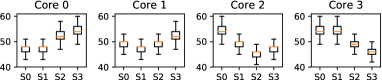
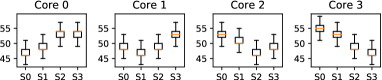
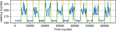
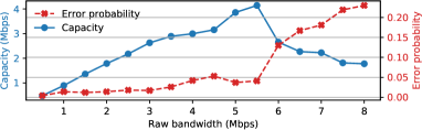
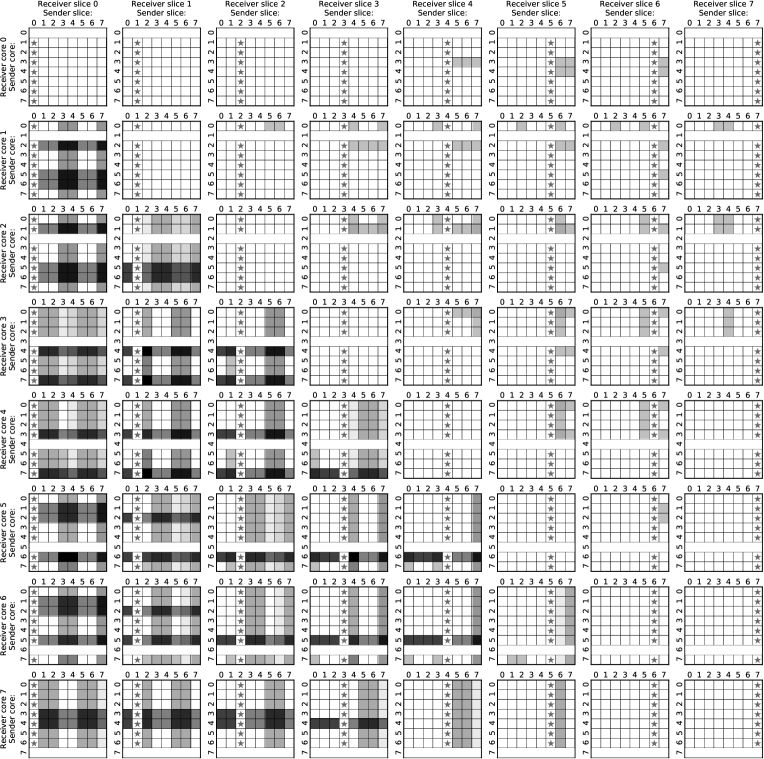
A.1 Reverse Engineering
Figure 10 shows the load latency on our Skylake CPU for all core-slice combinations and with two different target cache sets. These results, similarly to the ones for our Coffee Lake CPU that were shown in Figure 2, confirm that the load latency grows when the loads have to travel a longer distance on the ring, which matches the logical ring topology of Figure 1. We report an additional observation that we made while analyzing these results. Only on our Skylake CPU, the load latency from a target slice sometimes also depends on the parity of the target cache set. For example, the latency for core to perform a load from slice is smaller when the cache set is odd than when it is even. In the slice-core combinations where this behavior occurs, we observe it systematically for any odd or even set. This behavior does not affect our ring contention model. We hypothesize that it may be due to some LLC cache banking within individual LLC slices.
A.2 Covert Channel
Figures 11 and 12 show the results of the covert channel on our Skylake machine. In particular, Figure 11 reports a sample trace collected when the sender is transmitting a sequence of ones (peaks) and zeros (valleys) with a transmission interval of 4,000 cycles, showing that the two are visibly distinguishable. Observe that the configuration we picked this time (, , , ) is an example of a configuration that sees contention only when the prefetchers are turned on, which would normally not be subject to contention if the prefetchers were off (cf. Equation 1). Figure 12 reports the performance of our covert channel on Skylake, which reaches a maximum capacity of 4.14 Mbps (518 KBps) given a transmission interval of 727 cycles.
A.3 Side Channels


Attack on Cryptographic Code
Figures 14(a) and 14(b) show traces (averaged over 100 runs) from our attack on RSA and EdDSA on our Skylake machine. Both experiments are run with the attacker on core , timing loads from , and the victim on core . The general trends resemble the ones of our Coffee Lake results (cf. Section 5.1). For the attack against RSA, our classifier achieves an accuracy of 90% with prefetchers on and 87% with prefetchers off. For the attack against EdDSA, it achieves an accuracy of 95% with prefetchers on and 92% with prefetchers off.
Cache Cleansing
In our evaluation against cryptographic code, we implemented cache cleansing (to defend against preemptive scheduling attacks) by flushing the victim’s cache lines with clflush during context switches. Using clflush on every victim’s cache line is the best we can do on current hardware (the only secure alternative would be to use wbinvd that invalidates all caches, as in [35]). However, one may argue that with certain types of LLC partitioning (ensuring that victim and attacker do not share partitions even when time-sharing the same core), cleansing the LLC could be avoided. In this section, we show that even if only the L1/L2 caches needed to be cleansed on context switches, our attack would still go through. To this end, we repeat the attacks against RSA and EdDSA using an eviction-based L1/L2-only cleansing technique. To cleanse the L1d/L2, we iteratively access an eviction set with addresses for each cache set of the victim’s L2. To cleanse the L1i, we execute a sequence of jmp instructions over a 32 KB region (as in [76, 33]).151515This L1/L2 flushing approach may be incomplete as it makes assumptions on the replacement policy. Intel does not currently provide an instruction to reliably remove a cache line from the L1d, L1i and L2 caches only.
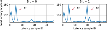
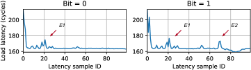
Figure 15(a) and 15(b) show traces collected by the attacker to leak one key bit of each victim (averaged over 100 runs). Because the victim only misses in the L1 and L2 but hits in the LLC, single iterations take less time than the ones we showed in Section 5.1, However, we can still see distinguishable ring contention patterns to recognize whether the secret bit was 0 or 1. For example, when we train our classifier with , , and (on Coffee Lake, with prefetchers on), we achieve an accuracy of 93% on RSA and 96% on EdDSA.
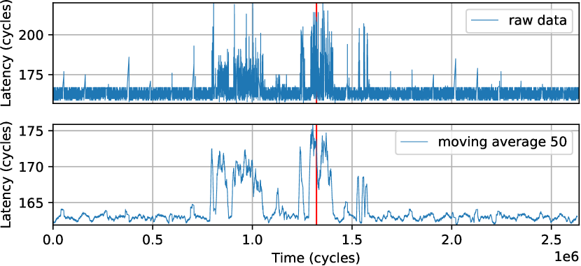
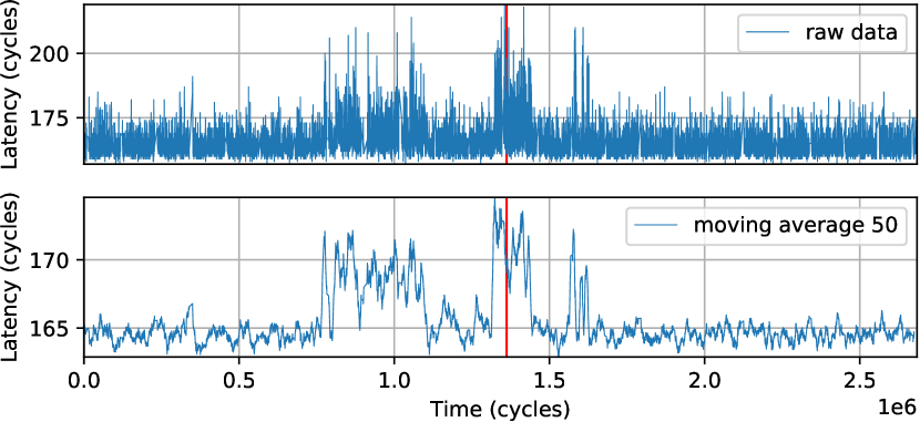
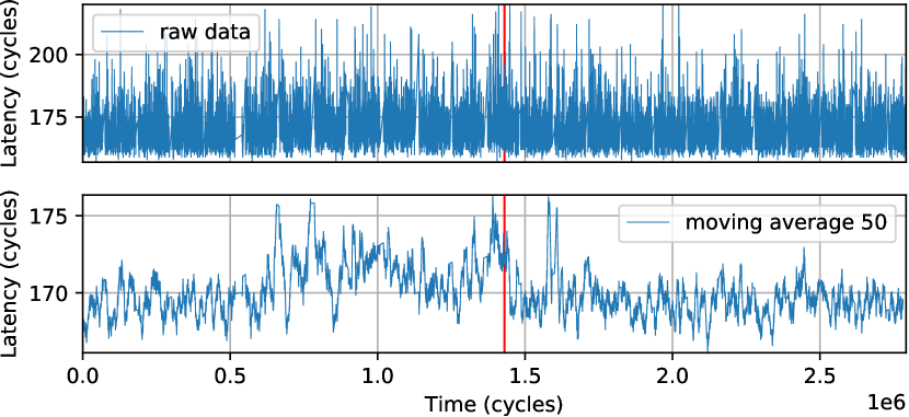
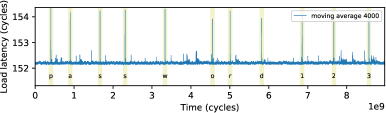
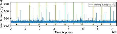
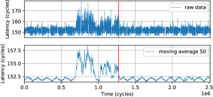
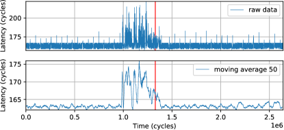
Keystroke Timing Attack
Figure 16(a) is a version of Figure 8 zoomed-in to show the precise contention pattern that occurs upon keystroke events. Figure 16(b) shows a trace collected while running stress -m N, with in the background. Observe that keystroke events are still easily distinguishable from the background noise. We get similar results when we run (Figure 16(c)). However, as the noise grows, with , we observe that keystroke events become harder to identify using a simple moving average (Figure 16(d)). Further, with , we observe that the keystroke events become almost entirely indistinguishable from noise.
Figures 17 and 19(a) show the results of the keystroke timing attack on our Skylake machine. Similarly to Coffee Lake, we observe distinguishable contention patterns in the absence of noise. We also repeat the experiments with background noise like above. We observe that with , keystrokes are still easily distinguishable from noise, but with they get harder to identify using a simple moving average.
Figures 18 and 19(b) show the results of the attack when keystrokes are typed on a local terminal (with physical keyboard input161616We tested the local typing scenario both on a tty and on a pty. We report results for the tty (Linux console) case, which is the harder case to attack (less code is executed to handle a keystroke on a tty than on a pty [7]). However, we were able to successfully run the attack in the pty case too.) on Coffee Lake. We observe that keystrokes are still easily distinguishable, albeit the precise contention patterns look different than the ones of the SSH typing scenario. One additional observation is that each keystroke-related peak in Figure 18 is followed by a second, smaller peak: we hypothesize that this second peak may be due to the processing of the key release event.171717In contrast, key release events are not transmitted over SSH. We also run the attack with background noise and observe results analogous to the ones above. We get similar results on our Skylake machine too.
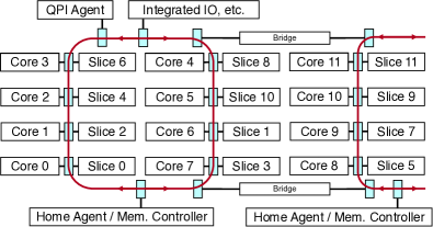
A.4 Results from a Server-class CPU
We now discuss preliminary results on a 12-core Intel Xeon E5-2687W v4 (Broadwell) CPU at 3.00 GHz. Figure 20 shows the ring topology we inferred from our analysis on such server-class CPU. This topology is different than the linear one of client-class CPUs (cf. Figure 1) in that it may include two rings (connected by bridges) instead of one. In particular, the CPU we tested featured one and a half rings, matching the high-level diagram reported in official sources [50, 119, 49] for a “Medium Core Count (MCC)” configuration. Despite the topological differences, however, the distributed (“boxcar” based) arbitration policy is the same. As a result, we were still able to launch our attacks. For example, with , , and , we were able to successfully run our covert channel. Similarly, with , and , we were able to replicate our side channel attack on cryptographic code, and with , we were able to replicate our keystroke timing attack. We found other sender/receiver configurations that lead to successful attacks too. However, we leave it to future work to exhaustively reverse engineer the ring agent clustering rules and derive the equivalents of Equations 1 and 2 for server-class CPUs. Finally, we made an additional observation on our Xeon CPU: under certain receiver configurations, the collected traces (including the effects of contention) sometimes scale up or down by constant offsets. We hypothesize that this behavior may be due to Uncore Frequency Scaling (UFS), which was added to Xeon CPUs with the Haswell microarchitecture [21]. However, this scaling is easy to account for due to its constant offset nature (when it kicks in, it looks like a step function).