Also at ]Dept. of Mechanical and Materials Engineering, Florida International University, Miami, FL33174, United States
Also at ]Nanoelectronics Integrated Systems Center (NISC), Nile University, Cairo, Egypt and ]Dept. of Electrical and Computer Engineering, University of Calgary, Calgary, Canada
Information Encoding/Decoding using the Memory Effect in Fractional-order Capacitive Devices
Abstract
In this study, we show that the discharge voltage pattern of a fractional-order supercapacitor from the same initial steady-state voltage into a constant resistor is dependent on the past charging voltage profile. The charging voltage was designed to follow a power-law function, i.e. , in which (charging time duration between zero voltage to the terminal voltage ) and () act as two variable parameters. We used this history-dependence of the dynamic behavior of the device to uniquely retrieve information pre-coded in the charging waveform pattern. Furthermore, we provide an analytical model based on fractional calculus that explains phenomenologically the information storage mechanism. The use of this intrinsic material memory effect may lead to new types of methods for information storage and retrieval.
Keywords : Fractional-order capacitors; Memory; Fractional calculus; Constant-phase element
Introduction
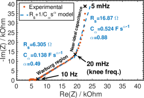
Many systems and processes in nature exhibit fractional-order behavior, such as vestibulo-ocular reflex Anastasio (1994), neuronal activity Teka, Marinov, and Santamaria (2014), ion channel gating Goychuk and Hänggi (2004), viscoelasticity Mainardi and Spada (2011), and disordered semiconductors Scher and Montroll (1975), which are models known to capture the existing short/long-term memory effects in these systems Sabatier and Farges (2014); Teka, Upadhyay, and Mondal (2017); Yuan, Fu, and Liu (2014); Ventosa-Santaulària, Heres, and Martínez-Hernández (2014). Supercapacitors are well-established types of electrochemical capacitive energy storage devices, but are also known to exhibit non-ideal, time-fractional-order electric behavior when charged by a power supply and discharged into a load Kant and Singh (2015); Allagui et al. (2016a); Allagui, Elwakil, and Freeborn (2017); Fouda et al. (2016); Allagui et al. (2018a, 2017). Their electric impedance can be modeled as a series resistance () with a fractional-order capacitor (also known as constant-phase element, CPE) over a certain frequency range; the reduced impedance of such a model is with , is a fractional-order capacitance in units of F sα-1, () is a dimensionless fractional exponent, and is the applied angular frequency in units of s-1 (see Nyquist plot of a commercially-available NEC/TOKIN supercapacitor in Fig. 1). In the time-domain, the current-voltage relationship of an -CPE-equivalent supercapacitor is expressed by the fractional-order differential equation Allagui et al. (2016b, 2018b):
| (1) |
where is the voltage across the CPE part ( for ), is the current flowing through the CPE, and is the applied charging voltage. The differentiation of non-integer order in equation 1 is defined as Podlubny (1999):
| (2) |
which can be viewed as a convolution with a hyperbolic function of frequency, and therefore contains a memory that progressively increases as the fractional order decreases Westerlund and Ekstam (1994); Westerlund (1991); Du, Wang, and Hu (2013). The physical interpretation of such fractional-order electric behavior of supercapacitors is still under debate, nonetheless, it has been widely attributed to the surface chemistry and morphological structure of the electrodes, which are usually composed of high-surface area and porous materials separated by an ionic conductor Córdoba-Torres, Mesquita, and Nogueira (2015); Alexander, Tribollet, and Orazem (2015, 2016); Alexander et al. (2017).
Despite the fact that fractional-order models involve hereditary effects, very few robust experimental proofs of this memory have been reported and investigated Westerlund (1991); Westerlund and Ekstam (1994); Uchaikin et al. (2016); Uchaikin, Sibatov, and Uchaikin (2009); Allagui, Zhang, and Elwakil (2018); Allagui et al. (2020). This Letter illustrates the memory effect in supercapacitors by sequentially encoding information into the charging pattern of the device, and then uniquely retrieving this code from the discharge pattern. The purpose here is to investigate this effect experimentally and mathematically using fractional-order models, which means that we are leaving the physical interpretation and potential applications of this effect to another study. The results are obtained on state-of-the-art, commercially-available devices which offer excellent stability, and relatively high-voltage ratings which facilitate repeatability and precise measurements.
Methods
We applied different charging voltage waveforms to a NEC/TOKIN supercapacitor (part #FGR0H105ZF, 5.5 V, 1 F111This device consists of six 0.917 V-aqueous electrolytic cells stacked in series; each cell is composed of two symmetric activated carbon + dilute sulfuric acid electrodes separated by a porous organic film) following the power-law function:
| (3) |
where is an exponent taking values between 0 (step voltage) and 1 (linear ramp), and is the rise time from 0 V to the steady-state value ( for this device), after which the charging voltage is turned off. The rise time is pre-defined so that the device will operate either in the capacitive tail from 20 mHz to 5 mHz, or in the Warburg region from 10 Hz to 20 mHz (see the two quasi-linear regions in Fig. 1). Prior to each applied charging voltage waveform, the supercapacitor was fully discharged into a constant 100 resistor () until its voltage was equal to 1 mV. Depending on the values of and , the charge waveforms used for information storage and the discharge waveforms used for information retrieval are given by the letter/number codes in Table 1. All charging/discharging experiments of the supercapacitor were programmed and executed sequentially on a Bio-logic VSP-300 electrochemical station using the EC-Lab control software. The time step for collecting data in all measurements was set to 10 ms.
| \ | 550 s | 275 s | 110 s | 55 s | 27 s |
|---|---|---|---|---|---|
| 1.0 | |||||
| 0.7 | |||||
| 0.4 | |||||
| 0.2 | |||||
| 0.1 |
Results
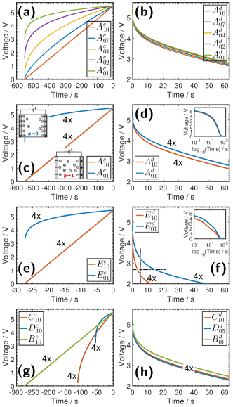
The experimental results are shown in Fig. 2. In the first column of the figure, we show several combinations of the charging voltage waveforms applied to the supercapacitor by varying the values of and (see Table 1). The time scale is shifted by to represent past events. The second column of the figure shows the first 60 s of the resulting voltage discharge waveforms into the same 100 resistor. Here the potentiostat acts as a constant resistance by controlling the current to maintain the ratio voltage/current constant. Fig. 2(b) shows five different voltage discharge profiles (, , , , ) after the device was charged with five different voltage waveforms (, , , , ) (Fig. 2(a)). The value of is made long enough so that the device will operate within its low frequency capacitive tail (Fig. 1). All discharging waveforms show first a quick voltage drop of ca. 0.5 V from the initial voltage into the internal series resistance of the device (), followed by a non-Debye inverse power law profile (i.e. Jonscher (1977); Westerlund and Ekstam (1994); Westerlund (1991); Jonscher (1999)). In Fig. 2(d), we show the discharge profiles of the device for four consecutive cycles (4x) alternating between code and code (Fig. 2(c)). The corresponding discharge waveform codes and are perfectly superimposed on each other demonstrating the repeatability of the charge/discharge process and the good stability of the device between one sequence to another. The results in Figs 2(a)-(d) show that the supercapacitor voltage discharge profile into the same constant resistance depends on the exponent in the charging voltage profile, and thus on its prehistory. This would not be the case for an ideal capacitor for which the exponential decaying voltage depends on the initial voltage , but not on how this voltage has been reached.. In other words, information can be encoded in the exponent being for example or (Figs. 2(c) and 2(d)) which can be used to encode a binary data sequence, or in multi-level logic using multiple values of (Figs. 2(a) and 2(b)).
The effect of the parameter is examined in Figs. 2(e) and 2(f), which depict the voltage profiles that were obtained in a similar way to the results shown in Figs. 2(c) and 2(d), respectively, but with a faster charging rate (). This value of corresponds to about 37 mHz frequency which belongs to the Warburg region and not the capacitive tail anymore (see Fig. 1). It is clear from Fig. 2(f) that the superposition of the code plots ( and ) obtained in response to the charging voltage codes and is again impeccable. Additionally, the difference between the discharge waveforms is more pronounced than when was set to (Fig. 2(d)) at which point the supercapacitor behaved as a near-ideal capacitor. Although the values of and are not same for these two cases, the correlation between the discharging and the charging voltage waveforms is stronger as decreases (equations 1 and 2) which makes another possible information coding dimension.
As for the decoding of the discharge pattern corresponding to a specific charge pattern, this can be carried out by a simple adaptive thresholding method either for a fixed time or fixed voltage. For example, as shown in Fig. 2(f), the thresholding can be performed at 5 seconds from the beginning of the discharge giving the two voltage values of 2.441 and 3.238 V for and (i.e. a difference of 0.797 V), respectively. Alternatively, it can be performed at a fixed voltage value of 2.7 V for example, leading to decoded time intervals of 3.109 and 14.31 s for and , respectively. It is important to note that decoding from the discharging waveform should be carried out way before the device is fully discharged, as shown in decimal algorithm scale in the insets in Figs. 2(d) and 2(f) depicting the quick convergence of the voltage-time profiles. The reason is that fractional-order behavior is space- and time-dependent; i.e. only in the transient time does the order of the state-space (represented by the values of ) manifest itself leading to the memory effect Allagui, Zhang, and Elwakil (2018); Allagui et al. (2020). In the steady-state time, fractional-order behavior becomes space-order independent.
Discussion
Analytically, the memory effect can be explained as follows. The voltage discharge response of the supercapacitor, modeled as an -CPE equivalent circuit, into a parallel resistance is given by Freeborn, Maundy, and Elwakil (2013):
| (4) |
where , , with (, ) is the two-parameter Mittag-Leffler function, and the initial voltage is given by where is the charging current obtained as (see equation 7). For , equation 4 can be rewritten in a dimensionless form as follows:
| (5) |
where , and . The Mittag-Leffler function in equation 5 depends on the CPE parameters and (and on ), whereas the parametric function is dependent also on how the device has been charged via the selection of one or both of the applied waveform parameters and . For an ideal capacitor, i.e. with and , we verify that equation 5 simplifies to which does not depend on its charge prehistory, as expected.
Now, to show the memory relationship, we derive the expression for the electrical charge stored in the device subjected to the charging waveform as follows Allagui, Zhang, and Elwakil (2018):
| (6) |
from which the current is found to be:
| (7) |
[Note that Equation 6 is obtained by equating with where is the solution of the fractional-order differential equation obtained using the inverse Laplace transform identity with (, , ) Podlubny (1999)]. At , the steady-state charge is a function of both parameters of the charge waveform ( and ) and those of the supercapacitor. [Equation 6 simplifies to for an ideal capacitance ( and ) using the identity which applies when . If (step voltage), the charge , otherwise is a function of ]. This is in line with our recent findings in which we highlighted that charging a supercapacitor with a voltage input results in a device and waveform-dependent accumulated electric charge Allagui, Elwakil, and Freeborn (2017); Allagui, Zhang, and Elwakil (2018); Allagui et al. (2020). In a dimensionless form, equation 6 looks like this:
| (8) |
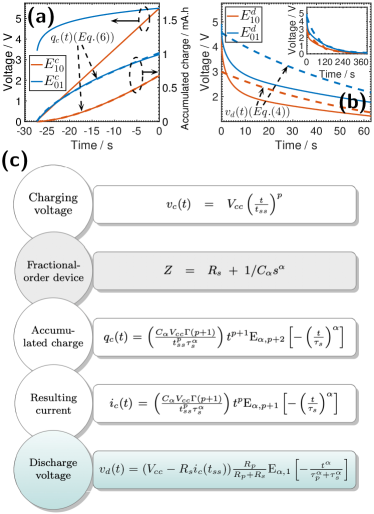
where . In Fig. 3(a), we show the measured and simulated (using equation 6) charge function for a fixed value of equal to 27 s, and steady-value voltage of 5.5 V. Two values of the parameter (i.e. 1.0 and 0.1) are selected. Equation 6 is in excellent agreement with the experiment using the values () equal to () for , and equal to () for obtained using least-squares fitting. Experimentally, the accumulated charge at time is found to be 0.68 and 0.99 mA h-1 for and , respectively. Given that all parameters in equation 6 are fixed apart from , it is evident that the information encoded in the value of is stored as . In Fig. 3(b), we show the resulting discharge voltage along with simulation using equation 4. The best fit is found using the values () equal to () for , and equal to () for , which can be improved if a sliding mode fitting is adopted instead. Note that the increase of the values of and towards those of a near-ideal capacitance is the result of the slow discharge rate.
Conclusion
We have shown that the voltage discharge of a supercapacitor that exhibits fractional-order temporal dynamics depends uniquely on the way by which it was charged. Figure 3(c) recapitulates the process from charging the device by an external power supply, to the accumulation of charge and the creation of current, and their relationship with the discharge voltage function which depends on the voltage charging parameters and . In other words, the supercapacitor remembers the pattern by which it was charged, and as a result, discharges accordingly.
The experimental results reported here were obtained on a commercial, high-capacitance supercapacitor which resulted in slow information storage and retrieval. Higher read-write rates should be possible in principle by using low-capacitance, fractional-order devices Agambayev et al. (2017). However, it is important in this case to ensure stability over a large number of cycles, as well as to reduce the effect of any parasitic capacitance for properly assessing the memory effect.
References
References
- Anastasio (1994) T. J. Anastasio, “The fractional-order dynamics of brainstem vestibulo-oculomotor neurons,” Biol. Cybern. 72, 69–79 (1994).
- Teka, Marinov, and Santamaria (2014) W. Teka, T. M. Marinov, and F. Santamaria, “Neuronal spike timing adaptation described with a fractional leaky integrate-and-fire model,” PLOS Comput. Biol. 10, e1003526 (2014).
- Goychuk and Hänggi (2004) I. Goychuk and P. Hänggi, “Fractional diffusion modeling of ion channel gating,” Phys. Rev. E 70, 051915 (2004).
- Mainardi and Spada (2011) F. Mainardi and G. Spada, “Creep, relaxation and viscosity properties for basic fractional models in rheology,” Eur. Phys. J. Spec. Top. 193, 133–160 (2011).
- Scher and Montroll (1975) H. Scher and E. W. Montroll, “Anomalous transit-time dispersion in amorphous solids,” Phys. Rev. B 12, 2455 (1975).
- Sabatier and Farges (2014) J. Sabatier and C. Farges, “Long memory models: a first solution to the infinite energy storage ability of linear time-invariant fractional models,” IFAC Proceedings Volumes 47, 2884–2890 (2014).
- Teka, Upadhyay, and Mondal (2017) W. W. Teka, R. K. Upadhyay, and A. Mondal, “Fractional-order leaky integrate-and-fire model with long-term memory and power law dynamics,” Neural Networks 93, 110–125 (2017).
- Yuan, Fu, and Liu (2014) N. Yuan, Z. Fu, and S. Liu, “Extracting climate memory using fractional integrated statistical model: A new perspective on climate prediction,” Sci. Rep. 4, 6577 (2014).
- Ventosa-Santaulària, Heres, and Martínez-Hernández (2014) D. Ventosa-Santaulària, D. R. Heres, and L. C. Martínez-Hernández, “Long-memory and the sea level-temperature relationship: a fractional cointegration approach,” PloS one 9, e113439 (2014).
- Kant and Singh (2015) R. Kant and M. B. Singh, “Generalization of Randles-Ershler admittance for an arbitrary topography electrode: application to random finite fractal roughness,” Electrochim. Acta 163, 310–322 (2015).
- Allagui et al. (2016a) A. Allagui, A. S. Elwakil, B. J. Maundy, and T. J. Freeborn, “Spectral capacitance of series and parallel combinations of supercapacitors,” ChemElectroChem 3, 1429–1436 (2016a).
- Allagui, Elwakil, and Freeborn (2017) A. Allagui, A. S. Elwakil, and T. J. Freeborn, “Supercapacitor reciprocity and response to linear current and voltage ramps,” Electrochim. Acta 258, 1081–1085 (2017).
- Fouda et al. (2016) M. E. Fouda, A. S. Elwakil, A. G. Radwan, and A. Allagui, “Power and energy analysis of fractional-order electrical energy storage devices,” Energy 111, 785–792 (2016).
- Allagui et al. (2018a) A. Allagui, A. S. Elwakil, M. Fouda, and A. G. Radwan, “Capacitive behavior and stored energy in supercapacitors at power line frequencies,” J. Power Sources 390, 142–147 (2018a).
- Allagui et al. (2017) A. Allagui, Z. Said, M. A. Abdelkareem, A. S. Elwakil, M. Yang, and H. Alawadhi, “DC and AC performance of graphite films supercapacitors prepared by contact glow discharge electrolysis,” J. Electrochem. Soc. 164, A2539–A2546 (2017).
- Allagui et al. (2016b) A. Allagui, T. J. Freeborn, A. S. Elwakil, and B. J. Maundy, “Reevaluation of performance of electric double-layer capacitors from constant-current charge/discharge and cyclic voltammetry,” Sci. Rep. 6, 38568 (2016b).
- Allagui et al. (2018b) A. Allagui, T. J. Freeborn, A. S. Elwakil, M. E. Fouda, B. J. Maundy, A. G. Radwanh, Z. Said, and M. A. Abdelkareem, “Review of fractional-order electrical characterization of supercapacitors,” J. Power Sources 400, 457–467 (2018b).
- Podlubny (1999) I. Podlubny, Fractional differential equations (Academic Press, 1999).
- Westerlund and Ekstam (1994) S. Westerlund and L. Ekstam, “Capacitor theory,” IEEE Trans. Dielectr. Electr. Insul. 1, 826–839 (1994).
- Westerlund (1991) S. Westerlund, “Dead matter has memory!” Phys. Scr. 43, 174 (1991).
- Du, Wang, and Hu (2013) M. Du, Z. Wang, and H. Hu, “Measuring memory with the order of fractional derivative,” Sci. Rep. 3, 3431 (2013).
- Córdoba-Torres, Mesquita, and Nogueira (2015) P. Córdoba-Torres, T. J. Mesquita, and R. P. Nogueira, “Relationship between the origin of constant-phase element behavior in electrochemical impedance spectroscopy and electrode surface structure,” J. Phys. Chem. C 119, 4136–4147 (2015).
- Alexander, Tribollet, and Orazem (2015) C. L. Alexander, B. Tribollet, and M. E. Orazem, “Contribution of surface distributions to constant-phase-element (cpe) behavior: 1. influence of roughness,” Electrochim. Acta 173, 416–424 (2015).
- Alexander, Tribollet, and Orazem (2016) C. L. Alexander, B. Tribollet, and M. E. Orazem, “Contribution of surface distributions to constant-phase-element (cpe) behavior: 2. capacitance,” Electrochim. Acta 188, 566–573 (2016).
- Alexander et al. (2017) C. L. Alexander, B. Tribollet, V. Vivier, and M. E. Orazem, “Contribution of surface distributions to constant-phase-element (cpe) behavior: 3. adsorbed intermediates,” Electrochim. Acta 251, 99–108 (2017).
- Uchaikin et al. (2016) V. Uchaikin, A. Ambrozevich, R. Sibatov, S. Ambrozevich, and E. Morozova, “Memory and nonlinear transport effects in charging–discharging of a supercapacitor,” Tech. Phys. 61, 250–259 (2016).
- Uchaikin, Sibatov, and Uchaikin (2009) V. Uchaikin, R. Sibatov, and D. Uchaikin, “Memory regeneration phenomenon in dielectrics: the fractional derivative approach,” Phys. Scr. 2009, 014002 (2009).
- Allagui, Zhang, and Elwakil (2018) A. Allagui, D. Zhang, and A. S. Elwakil, “Short-term memory in electric double-layer capacitors,” Appl. Phys. Lett. 113, 253901–5 (2018).
- Allagui et al. (2020) A. Allagui, D. Zhang, I. Khakpour, A. S. Elwakil, and C. Wang, “Quantification of memory in fractional-order capacitors,” J. Phys. D 53 (2020).
- Note (1) This device consists of six 0.917\tmspace+.1667emV-aqueous electrolytic cells stacked in series; each cell is composed of two symmetric activated carbon + dilute sulfuric acid electrodes separated by a porous organic film.
- Jonscher (1977) A. K. Jonscher, “The ’universal’ dielectric response,” Nature 267, 673–679 (1977).
- Jonscher (1999) A. K. Jonscher, “Dielectric relaxation in solids,” J. Phys. D: Appl. Phys. 32, R57 (1999).
- Freeborn, Maundy, and Elwakil (2013) T. J. Freeborn, B. Maundy, and A. S. Elwakil, “Measurement of supercapacitor fractional-order model parameters from voltage-excited step response.” IEEE J. Emerg. Sel. Topics Circuits Syst. 3, 367–376 (2013).
- Agambayev et al. (2017) A. Agambayev, S. P. Patole, M. Farhat, A. Elwakil, H. Bagci, and K. N. Salama, “Ferroelectric fractional-order capacitors,” ChemElectroChem 4, 2807–2813 (2017).