Reinforcement Learning Trajectory Generation and Control for Aggressive Perching on Vertical Walls with Quadrotors
Abstract
Micro aerial vehicles are widely being researched and employed due to their relative low operation costs and high flexibility in various applications. We study the under-actuated quadrotor perching problem, designing a trajectory planner and controller which generates feasible trajectories and drives quadrotors to desired state in state space. This paper proposes a trajectory generating and tracking method for quadrotor perching that takes the advantages of reinforcement learning controller and traditional controller. The trained low-level reinforcement learning controller would manipulate quadrotor toward the perching point in simulation environment. Once the simulated quadrotor has successfully perched, the relative trajectory information in simulation will be sent to tracking controller on real quadrotor and start the actual perching task. Generating feasible trajectories via the trained reinforcement learning controller requires less time, and the traditional trajectory tracking controller could easily be modified to control the quadrotor and mathematically analysis its stability and robustness. We show that this approach permits the control structure of trajectories and controllers enabling such aggressive maneuvers perching on vertical surfaces with high precision.
Index Terms:
Aggressive flight, reinforcement learning, quadrotorI Introduction
Micro Aircraft Vehicles (MAVs) are widely being researched and employed due to their relative low operation costs and high flexibility in various applications. The applications include search and rescue [2], wind turbine inspection [13, 8], reconnaissance and mapping [3], target tracking, environmental monitoring, etc.
Most of the quadrotor is powered by battery for motor driving and generate lift, which gives a limited time for quadrotor tasks performing. Flying with a power cable connected to power supply on ground [5, 1, 9] can solve the problem but the quadrotor can only be operated in a specific and relative open area. If the quadrotor can perch on arbitrary angle surface such as vertical wall to reduce its battery consumption while keeping environment monitoring using on-board camera or even for battery charging. The mission time can be extended with a great amount of time.
The quadrotor is an under-actuated system, meaning it cannot control its position while maintaining arbitrary attitude. To successfully perch on the wall, quadrotors using gripper mechanism [16, 18, 7] to perch on vertical walls had been proposed. However, the perching device would cost additional energy consumption. Another approach for perching is using aggressive maneuver to land without adding mechanism on quadrotor.
There are a few other researches discussing perching of traditional quadrotors. To land a traditional quadrotor, the process can be separated into two different parts, 1) Trajectory planning to the target landing point. 2) Track the designed trajectory and land. To generate a feasible trajectory, Quadratic Program problem were formulated under the dynamics constrain of quadrotor [17, 11].
Using Reinforcement Learning (RL) for low-level quadrotor control has been proposed and shown its implementation result in real world quadrotor to stabilize and hover or fly on a specific trajectory [6, 12]. The advantage of using RL controller is due to its nonlinearity and fast computation. However, there exist a gap showing on the tracking result while transferring the RL controller on quadrotors from simulation to real world experiment. In reality condition, the quadrotor hovering and tracking results didn’t perform as same as the results in simulation. The reason is that the RL-based controller is sensitive to the deviation of model physical parameters such as take-off weight or motor characteristic. This situation can be harsher when considering aggressive maneuver using RL controlling the motors directly.
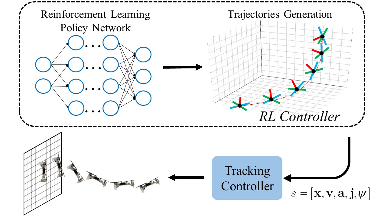
To fix this problem, we propose a method that takes the advantages of RL controller and traditional controller illustrated in Fig. 1. First, we train a RL controller to learn how to perch the quadrotor to the set point by directly command the thrust force of each motor. Second, we create a simulated quadrotor which has the same initial states as the real quadrotor. The trained low-level RL controller would manipulate quadrotor toward the landing point in simulation environment. Third, we extract the trajectory information in simulation and send it to traditional controller on real quadrotor. Generating feasible trajectories via the trained RL controller would require less time, and the traditional trajectory tracking controller could easily be modified to control the quadrotor and mathematically analysis its stability and robustness. Moreover, this combined structure of controller can be implement to different physical parameters or different type of vehicle.
In Section II, the dynamics of quadrotor and reinforcement learning algorithm were presented. Section III and Section IV describes the RL perching training for trajectory generating and the traditional controller design to perform perching task. Section V shows the successful application of the combined structure to the quadrotor, and Section VI conclude the paper.
II Methodology
The first challenge of planning is that since the quadrotor is an under-actuated system, the designed trajectory needs to be feasible with respect to the system dynamic constrains. A possible technique is to solve a constrained optimization, for example:
| (1) |
where is run time cost, terminal cost, system dynamic, input action, and is the initial state. With this scheme, we can obtain a suitable trajectory with respect to time.
In this paper, we assuming dynamic trajectory planning problem can be described by a Markov decision processes (MDP), with this property the best decisions are independent to the history. Next, we utilize reinforcement learning to search the feasible solutions in (1) while the searching results were memorized by an artificial neural network. With this scheme, the searching cost passes through the training phase.
II-A Reinforcement Learning
Reinforcement learning (RL) is one of basic machine learning paradigms, aim to solve MDP through learning processes. In this section, we provide a short introduction to reinforcement learning.
A Markov decision processes is described by a 4-tuple where is the state space, is action space, is transition probability and is the reward function. The goal of MDPs is to find a policy
| (2) |
that maximize cumulative discounted reward
| (3) |
where is discounting factor. To connect (1), we write MDP statement as follow:
| (4) |
where , is the initial state distribution. For a given policy , the following recurrent relation hold
| (5) |
where
| (6) |
The quantity
| (7) |
can be used for determine that which action is good with respect to policy . In fact, we can guarantee [12] that a policy is better than policy if
| (8a) | |||
| or | |||
| (8b) | |||
Therefore, for a policy search iteration, Equation (8) provides an improvement guideline to distinguish whatever an action should be memorized or not.
II-B Quadrotor Dynamics
The simplest way to modeling a multi-rotor is considered as a rigid body dynamics
| (9) |
where is rotation matrix, is angular velocity on body frame, and the hat map is defined as the condition [10]. The , , and are position, velocity, acceleration with respect to inertia frame, is the momentum of inertia, is the mass of rigid body. is the gravity acceleration. The force and moment model of each quadrotor motor can be simplified as
| (10) |
where is the rotation speed of motors and . , are the coefficient of lift and moment. The relation between moment , force of quadrotor and motor speed can be written as
| (11) |
where is the physical dimension of quadrotor.
II-C Training and Inference
Integrating (9), (11) and Euler method, we can obtain the discrete time transfer function of a quadrotor
| (12) |
where and . We change our objective in terms of deterministic transition and the main objective become
| (13) |
in practice.
Actor-Critic architecture is used in this paper. The value network (Critic), was trained by a V-trace method [4], which is a modified temporal difference (TD) learning [14]. The policy network (Actor), was trained according to (8) through hinge loss. In addition, since (8) can be satisfied by adjusting the likelihood per pair of state and action , we replace the likelihoods by its log of likelihood for simplifying the complexity in gradient calculation. The summarized objective is listed as follows
| (14) |
where is the margin to make the samples that already satisfied (8) not to provide losses for policy improvement [12].
Notice that since the simplified rigid body dynamic is independent to the rotor number. The different physical configurations are only effect on and , the trained RL policy could be implemented directly on to quadrotors. Unfortunately, training RL controller on simplified ideal environment and transfer to real world still exists system uncertainty and system response latency. These factors may lead to the quadrotor become unstable especially under aggressive maneuver situation. To overcome this problem, we consider a hybrid control strategy and introduce a tracking algorithm in next section.
III Simulation Environment and Trajectory Generating Result
In this section, we used the aforementioned dynamic equations and reinforcement algorithms to train a quadrotor perching policy controlling the four motors output directly which can successfully landing on the vertical wall. The reward function for RL training is designed as follows
| (15) |
where , , and are angle error, position error, and action output. to are the weights of the error, and is the distance between quadrotor to the perching point on -axis. For RL value and policy neural network construction, 3-layer with 32 and 128 nodes were used. The policy network outputs four motors thrust command to control the quadrotor perching task.
Once the quadrotor lands successfully in the simulator controlled by RL policy neural network, we extract the trained controller for generating feasible trajectory. The trajectory contains position, velocity, acceleration, jerk, and yaw angle information and use designed traditional controller to track along the planned path.
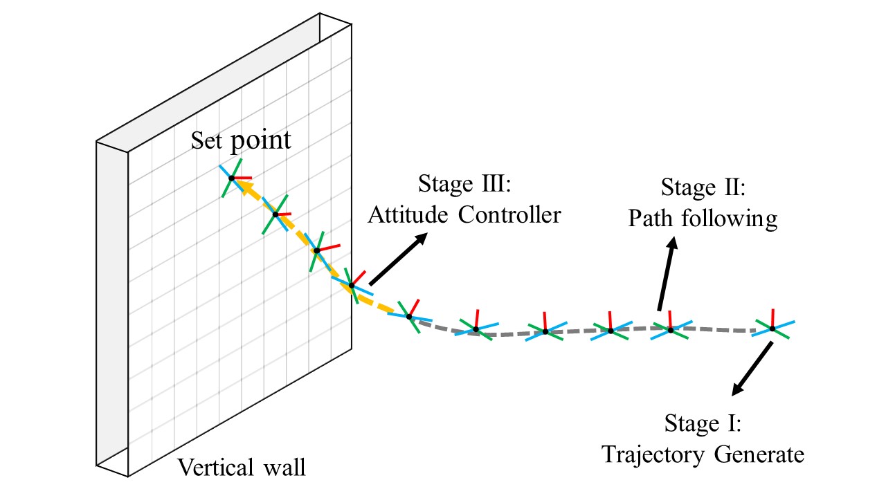
We design a sequence for controlling the quadrotor during operating the mission and can be separated into following three stages and shown in Fig.3:
-
•
Stage I: Trajectories generation
-
•
Stage II: Path following
-
•
Stage III: Attitude control
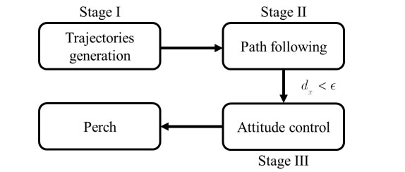
In stage I, feasible trajectory would be generated from the current state of quadrotor and can successfully perch to desired point eventually. During the path following stage, the controller keeps tracking on the desired path with the information of position, velocity, acceleration, jerk, and yaw angle until the quadrotor approaches the launch point. As the distance is shorter than designed threshold , quadrotor switch to stage III and attitude control would be triggered. During the attitude control stage, the controller attempt to stable the quadrotor to final pose and perch on the set point of a vertical plane. While the quadrotor reaching the original point with pitch angle of , it would be considered to be a successful cases to landing onto the vertical surface.
IV Controller Design
In this section, we introduce our controller for trajectory tracking along perching neural network behavior. The tracking and perching consist of two controllers as follows,
1. Trajectory Tracking Control: controlling the quadrotor center of mass to follow the three-dimensional path including position, velocity, acceleration, and jerk information from RL trajectory generator.
2. Attitude Control: controlling the quadrotor to desired roll, pitch and yaw angle from trajectory tracking controller command.
IV-A Trajectory Tracking Control
The tracking controller is based on proportional-derivative (PD) controller and can be written as following expression,
| (16) |
where is the desired acceleration vector of quadrotor, are the control references from trajectory generator, , and are the feedback, and are the gains of each component. The total thrust and desired attitude expressed in rotation matrix form can be derived as
| (17) | ||||
where
| (18) | ||||
is the desired heading angle, and is always greater than 0 because the quadrotor would not operate upside down in trajectory tracking control.
IV-B Attitude Control
The attitude controller not only receive the command from trajectory tracking control but also switch to final perching attitude . The controller consists of dual-loop control structure. The outer loop P control in (21) determines the desired angular velocity of quadrotor, where switches according to the distance of quadrotor to perching point on -axis .
| (19) |
The error of rotational angle between and measurement feedback is given by
| (20) |
where the vee map is the mapping [10], and the desired angular velocity is derived as
| (21) |
The is the feed-forward term given from trajectory tracking controller, which use the jerk of the trajectory to compensate angular velocity command of the quadrotor [15].
The inner loop uses a PID controller for desired angular acceleration shown in (22).
| (22) | ||||
where is the feedback of quadrotor angular velocity.
V Simulation Results
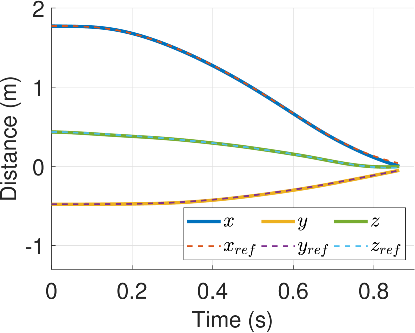
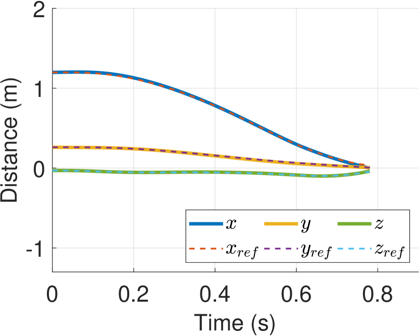
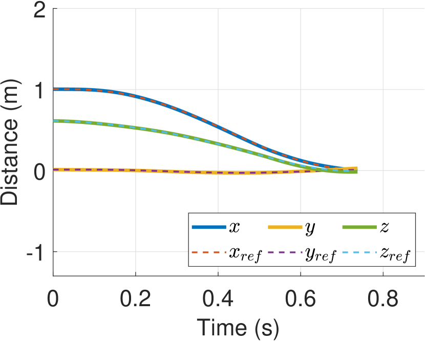
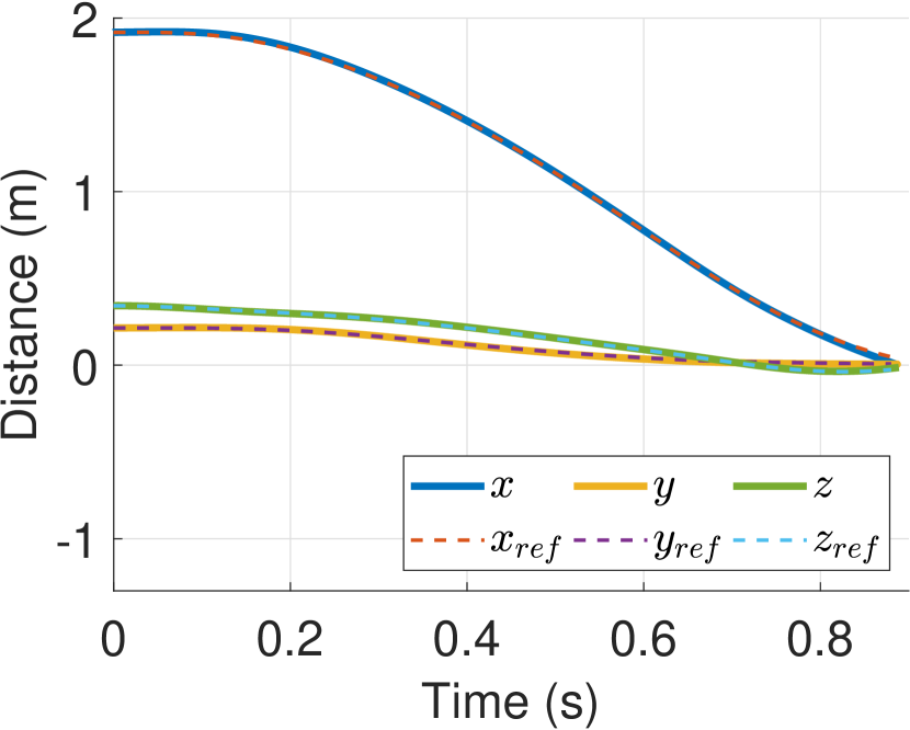
To verify that our proposed perching trajectory generating and tracking structure could successfully landing on the wall, we conduct 50 flight tests starting from arbitrary initial position and velocity in a space in front of the perching point in the simulation environment illustrates in Fig. 2. All trails perch to the set position successfully. Fig. 4 shows four flight results start from different initial condition. Table. I shows the mean and standard deviation (SD) of the distance error and pitch angle while the The vehicles touch the wall. The simulation experiment shows while the quadrotor reach to , the mean distance error to the landing point on and is cm and cm. The mean pitch angle is .
| Mean | SD | |
| -axis | cm | 0.2 cm |
| -axis | cm | 0.21 cm |
| pitch angle |
VI Conclusion
In this paper, we present a quadrotor perching control structure which combining RL trajectory planning and traditional tracking controller. The complex nonlinear dynamic constrain optimization problem can be solved by using trained RL trajectory planner to find a feasible path rapidly. A well designed traditional controller can guarantee the stability of quadrotor. The control structure can make up the uncertainty using RL control policy output directly to motors when it has disturbance in operation or modeling imperfection in RL training process. The perching simulation in Section V demonstrates the quadrotor follows the trajectory generated by RL control policy and perches to designed point with standard deviation cm on -axis and pitch angle in average on the wall.
Future work will focus on the real-world implementation, verify the overall control structure perching performance, and observing the robustness while facing disturbance and model uncertainties. However, the long term goal is to perform tasks physical contact such as battery charging or environment monitoring.
References
- [1] Michele Bolognini and L. Fagiano. Lidar-based navigation of tethered drone formations in an unknown environment. ArXiv, abs/2003.12981, 2020.
- [2] K. Choutri, M. Lagha, and L. Dala. A fully autonomous search and rescue system using quadrotor uav. 2020.
- [3] P. Durdevic, D. Ortiz-Arroyo, and Z. Yang. Lidar assisted camera inspection of wind turbines: Experimental study. 2019 1st International Conference on Electrical, Control and Instrumentation Engineering (ICECIE), pages 1–7, 2019.
- [4] Lasse Espeholt, Hubert Soyer, R. Munos, K. Simonyan, V. Mnih, Tom Ward, Yotam Doron, Vlad Firoiu, T. Harley, Iain Dunning, S. Legg, and K. Kavukcuoglu. Impala: Scalable distributed deep-rl with importance weighted actor-learner architectures. ArXiv, abs/1802.01561, 2018.
- [5] L. Fagiano. Systems of tethered multicopters: Modeling and control design. IFAC-PapersOnLine, 50:4610–4615, 2017.
- [6] J. Hwangbo, I. Sa, R. Siegwart, and M. Hutter. Control of a quadrotor with reinforcement learning. IEEE Robotics and Automation Letters, 2:2096–2103, 2017.
- [7] A. Kalantari, Karan Mahajan, D. Ruffatto, and M. Spenko. Autonomous perching and take-off on vertical walls for a quadrotor micro air vehicle. 2015 IEEE International Conference on Robotics and Automation (ICRA), pages 4669–4674, 2015.
- [8] Evan Kaufman, Kuya Takami, Zhuming Ai, and Taeyoung Lee. Autonomous quadrotor 3d mapping and exploration using exact occupancy probabilities. 2018 Second IEEE International Conference on Robotic Computing (IRC), pages 49–55, 2018.
- [9] Taeyoung Lee. Geometric controls for a tethered quadrotor uav. 2015 54th IEEE Conference on Decision and Control (CDC), pages 2749–2754, 2015.
- [10] Taeyoung Lee, M. Leok, and N. McClamroch. Geometric tracking control of a quadrotor uav on se(3). 49th IEEE Conference on Decision and Control (CDC), pages 5420–5425, 2010.
- [11] Daniel Mellinger, Nathan Michael, and Vijay Kumar. Trajectory generation and control for precise aggressive maneuvers with quadrotors. The International Journal of Robotics Research, 31:664 – 674, 2012.
- [12] Chen-Huan Pi, Kai-Chun Hu, Stone Cheng, and I-Chen Wu. Low-level autonomous control and tracking of quadrotor using reinforcement learning. Control Engineering Practice, 95:104222, 2020.
- [13] Bjorn E. Schafer, D. Picchi, T. Engelhardt, and D. Abel. Multicopter unmanned aerial vehicle for automated inspection of wind turbines. 2016 24th Mediterranean Conference on Control and Automation (MED), pages 244–249, 2016.
- [14] R. Sutton. Learning to predict by the methods of temporal difference learning. 1988.
- [15] Ezra Tal and Sertac Karaman. Accurate tracking of aggressive quadrotor trajectories using incremental nonlinear dynamic inversion and differential flatness. 2018 IEEE Conference on Decision and Control (CDC), pages 4282–4288, 2018.
- [16] Justin Thomas. Grasping, perching, and visual servoing for micro aerial vehicles. 2017.
- [17] Justin Thomas, M. Pope, Giuseppe Loianno, E. Hawkes, M. A. Estrada, Hao Jiang, M. Cutkosky, and V. Kumar. Aggressive flight with quadrotors for perching on inclined surfaces. Journal of Mechanisms and Robotics, 8:051007, 2016.
- [18] Haijie Zhang, Jiefeng Sun, and Jianguo Zhao. Compliant bistable gripper for aerial perching and grasping. 2019 International Conference on Robotics and Automation (ICRA), pages 1248–1253, 2019.