Arraymetrics: Authentication Through Chaotic Antenna Array Geometries
Abstract
Advances in computing have resulted in an emerging need for multi-factor authentication using an amalgamation of cryptographic and physical keys. This letter presents a novel authentication approach using a combination of signal and antenna activation sequences, and most importantly, perturbed antenna array geometries. Possible degrees of freedom in perturbing antenna array geometries affected physical properties and their detection are presented. Channel estimation for the plurality of validly authorized arrays is discussed. Accuracy is investigated as a function of signal-to-noise ratio (SNR) and number of authorized arrays. It is observed that the proposed authentication scheme can provide 1% false authentication rate at SNR, while it is achieving less than 1% missed authentication rates.
Index Terms:
antenna arrays, authentication, chaotic communication, communication system security, MIMO communication.I Introduction
The emergence of quantum computing has recently shown that currently used conventional encryption techniques can be cracked with ease in the near future [1]. This pushed researchers to finding new horizons that satisfy security requirements through the use of non-cryptographic approaches [2], such as utilizing the PHY properties of the system [3] or machine learning (ML) techniques [4] to infer presence of adversaries and defend accordingly. Quantum password cracking aside, PHY authentication becomes critical in authenticating simplex broadcasts in which cryptographic approaches cannot be utilized, such as spoofed global positioning system (GPS) signals as in [5]. In [6], layered security approaches were investigated in detail, and were shown to be redundant and inflexible for future network structures [7].
Authenticating user equipments (UEs) using their PHY characteristics in developing a PHY security (PLS) approach have been gaining traction[8]. The idea of extracting artifacts caused by imperfections in the source network interface card (NIC) to authenticate devices have been around for more than a decade [9]. Channel similarities in addition to the RF fingerprint of the device, of which recent extraction advances is detailed in [10], are also utilized in the control-layer based authenticator designed in [11], that aims to replace high-latency connections to remotely located authentication servers with local verification among fifth generation (5G) heterogeneous network (HetNet) access points (APs).
Antenna array geometry optimization literature has historically focused on designing "smart" [12] or adaptive antenna arrays with improved far- or near-field spatiospectral localization[13]; and is rich in this context. Although PLS using multiple antennas was also introduced more than a decade ago when signals received from MIMO transmitters are authenticated using the spatiospectrotemporal correlation of the wireless channel in [14]. However, due to the randomness of the channel this method can provide limited control on spatiospectrotemporal signatures. Despite the further studies of PHY security of MIMO systems in [15, 16], the literature for PHY authentication for this systems remains underdeveloped to date.
Physical layer security aspect of multiple antenna configurations were most recently evaluated to the extent of passive confidentiality and active availability attacks using MaMIMO systems [17]. Recent developments in signals intelligence (SIGINT) techniques for MIMO wireless communications are surveyed in [18]. A secure receive spatial modulation scheme that randomizes precoders but not antenna arrays is proposed in [19].
In this work, we propose a novel authentication scheme that combines chaotic antenna array geometries with pseudorandom pilot sequences and antenna array activation sequences. This novel approach combining all three allows unclonable authentication devices, even if the adversaries eavesdrop the message exchange or figure out the unique antenna array geometry by x-ray radiography. The accuracy and scalability of the approach is investigated. It is observed that the proposed authentication scheme can provide 1% false authentication rate at SNR, while it is achieving less than 1% missed authentication rates.
The rest of this paper is organized as follows: Section II provides the adopted system model. Section III introduces the proposed chaotic and pseudorandom designs and briefly presents their effects on the detection metrics. The detection performance results are shown in Section IV. Finally, the paper is concluded in Section V.
Notation: Throughout this paper, vectors are represented using lowercase bold-face letters, matrices are uppercase bold-face letters, and non-bold letters are used for scalars. The superscripts stands for the conjugate-transpose operation. , and represent the complex, integer and real number domains, respectively. corresponds to complex Gaussian distributed random variable with mean and variance , and corresponds to the uniformly distributed random variable between and . corresponds to the Euclidean norm, and correspond to the Hadamard multiplication of matrices and and division of matrix to , respectively.
The authenticating device and the device being authenticated will hereinafter be referred to as "Seraph" and "Neo", respectively, with subscripts and used to describe their respective attributes.
II System Model
The working principle of this system is similar to that of an active RF identification (RFID) tag. However, instead of the device-specific variation of binary load state or load impedance as a function of time, it is assumed that upon their first encounter which takes place in a controlled environment, Seraph characterizes and saves the following identifying information about Neo in an allowlist:
-
•
The chaotic antenna array geometry equipped by Neo, as exemplified in Fig. 1,
-
•
The particular antenna activation sequence used by Neo,
-
•
The particular pilot sequence transmitted by Neo.
This section contains technical definitions for these information sources. This section and subsequent sections investigate ensuing encounters, during which Seraph authenticates Neo’s identity by simultaneously verifying all abovementioned attributes of Neo real-time in uncontrolled environments. The analysis further assumes that, as is the case with RFID tags, Seraph and Neo are synchronized; and the wireless propagation channel between each antenna of Seraph and Neo is representable in the form of a single tap over the utilized bandwidth without loss of generality, is also time-invariant throughout the transmission interval, and is known by Seraph through readily available techniques.
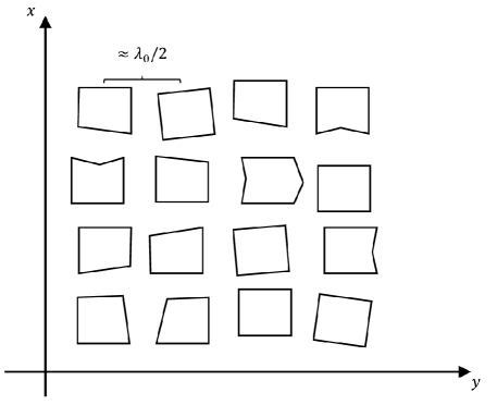
Neo is equipped with antennae wherein and correspond to the number of antennae on the horizontal and vertical edges of Neo’s 2D antenna array. Neo’s 2D antenna array starts off as a standard spaced uniform linear antenna array (ULAA), where is the free space wavelength at the center carrier frequency. Each antenna element starts off as square patch of edge length , where is the guided wavelength at the center carrier frequency, and each vertex of each antenna element is translated from its original location as , where is the final coordinate of the th the vertex of the th antenna element, is the original coordinate thereof, and are both and denote the horizontal and vertical displacement of the aforementioned vertex from its original location, respectively, and and are the horizontal and vertical unit length vectors, respectively. Furthermore, the joint probability density function (PDF) for any two displacement satisfies . Note that by independently displacing all vertices in two dimensions, each antenna element is translated, rotated, scaled or skewed chaotically from the ULAA design as illustrated in Fig. 1. As a result, it is assumed that complex noise is introduced to Neo’s spatial signature in the transmit direction of [20] as
| (1) |
wherein is the spatial signature of Neo’s nonmodified ULAA in the transmit direction of as described in [20, Eq. (7.24)] of which construction is not recited here due to space constraints, is the standard deviation thereof and corresponds to the positive square root of the channel gain, is Neo’s nonmodified ULAA s unit spatial signature in the transmit direction of as described in [20, Eq. (7.25)], and is the introduced chaotic noise of which each element is independent from others. Accordingly, we will refer to Neo’s final ULAA s unit spatial signature in the transmit direction of as
| (2) |
Each antenna is connected to an independent RF chain that is capable of carrying a complex (IQ modulated) sinusoid pulse uncorrelated to those of other antennae. The reciprocal of the duration of each pulse is analogous to widely known "baud rate" and is assumed constant, at least for Neo, to ease practical aspects concerning transceiver implementation. Neo may also utilize nonsinusoidal wavelets, or, further utilize plurality of wavelets wherein each signal element utilizes a different wavelet for further scalability and security, but these are beyond the scope of this art and will be considered in future works to maintain the work in hand concise. Neo transmits the pilot sequence over baud intervals, and the pilot symbol modulating the sinusoid transmitted from the th antenna during the th baud interval is given in the th row and th column of the pilot matrix and denoted by , wherein and
| (3) |
where is a random variable that determines whether Neo’s th antenna during the th baud interval and is Neo’s activation threshold that determines the antenna activation probability; furthermore . A zero entry in implies that no transmission occurs from that antenna during that baud interval. Therefore, describes the particular antenna activation sequence used by Neo in its columns, and the particular pilot sequence transmitted by Neo in its elements.
Seraph is equipped with antennae that is formed in a nonmodified 2D ULAA, and has the default spatial signature thereof. Accordingly, the channel matrix is composed as done in [20, Eq. (7.56)], with the difference being the unit spatial signature in the transmit direction of term denoted by is replaced with derived in (2). The signal received at Seraph’s th antenna at the end of the th baud interval is given on the th row and th column of , where
| (4) |
where is the additive white Gaussian noise (AWGN) matrix comprising independent elements identically distributed with wherein is Neo’s SNR.
III Proposed Receiver
Since Seraph relies on random deviations of spatial signature, a detection algorithm for Neo’s spatial signature deviation can be implemented to decide if the received signal is coming from Neo or not. The detection algorithm can be derived by correlating Neo’s expected received signal over . The correlation is calculated using
| (5) |
Noise or signal emitted by intruders may also cause high correlation and can cause false positives if solely this measurement is considered. To distinguish Neo’s signal both from noise and signals emitted by intruders, its strength must be compared to that of noise. The noise variance, , is estimated by similarly correlating with any signature orthogonal to that of Neo and all other possible authorized users. The detection metric is then given by
| (6) |
The detection metric is then compared to a threshold value (). To minimize the error, one threshold can be selected as half of the distance between two states as
| (7) |
However, is not a good threshold for low SNR scenarios, which results in high false alarm (FA) rates. To prevent that, a threshold () can be precalculated to fix the FA probability to a designed value. FA probability can be represented as
| (8) |
which is . The final threshold is found as the combination of both thresholds as
| (9) |
to improve the performance of the system. Performance analysis for a variety of false alarm thresholds is presented in Sec. IV.
IV Performance Analysis
To evaluate the proposed authentication method, link level simulations have been performed under highly scattering Rayleigh channel. Seraph is assumed to have 512 antennas at all times, while Neo may have different number of active antennas depending on .
In Fig. 2, missed detection rate of Neo’s signature is presented against SNR. The proposed method fails to authenticate Neo with less than 1% probability at most at SNR if antennas are activated while . It is also seen that 1% misdetection probability can be achieved when SNR for both and active antennas with relaxed FA requirement of . Lower rates are possible as the number of active antennas are increased or FA probability requirement is relaxed.
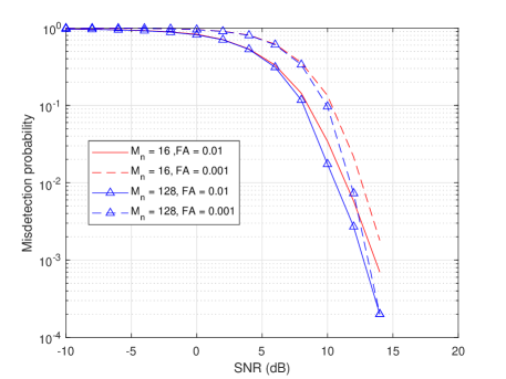
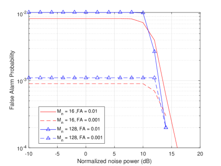
Fig. 3 shows FA rates of Neo’s signature when Seraph is only receiving noise. As it is seen from the figure, the desired FA rates of and are closely achieved for SNR values up to , respectively. After that, SNR values the secondary threshold of becomes effective and improves the FA performance for Neo’s signature detection algorithm. The authors note that, due to the designed threshold calculation based on the desired false detection rate, both results are expected to be as close as possible to or depending on the threshold. Since higher number of antennas provide better diversity against fading and noise, increasing the number of antennas provides more consistent behaviour that yield results closer to expected. Lower number of antennas may result in reduced false alarm rates due to the way the detector is structured, but increasing number of antennas results in more consistent overall detection performance also considering the misdetection rates shown in Fig. 2.
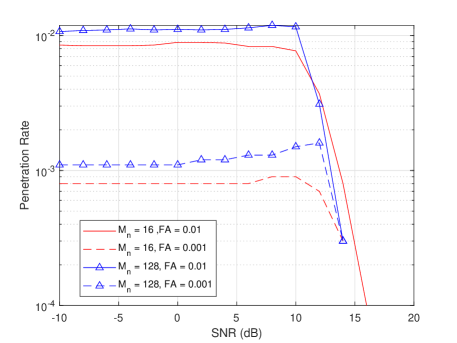
The penetration rate of a random signature intruder is presented in Fig. 4. In this scenario, Seraph receives a random signal from a transmitter which has a random signature that is different than Neo’s signature. As seen in Fig. 4, penetration test performance shows similar behaviour to the noise-only scenario presented in Fig. 3. Due to increased signal power and FA rates being fixed for noise only scenario, FA rates slightly increases at around SNR. Then similar to previous case, after SNR values of and for and , respectively, the secondary threshold of becomes effective and improves the FA performance.
V Concluding Remarks
A novel authentication approach combining chaotic antenna array geometries with signal and antenna activation sequences has been presented. Possible degrees of freedom in perturbing antenna array geometries, affected physical properties and their detection are presented. While enforcing false alarm rate to be less than 1%, the proposed authentication method is able to provide less than 1% missed detection rates above It is observed that the proposed authentication scheme can provide 1% false authentication rate at SNR. Practical approached to randomized chaotic antenna array manufacturing and statistical signature distribution of the manufactured arrays can be investigated as a future study.
References
- [1] P. W. Shor, “Algorithms for quantum computation: discrete logarithms and factoring,” in Proceedings 35th Annual Symposium on Foundations of Computer Science, 1994, pp. 124–134.
- [2] C. H. Bennett and P. W. Shor, “Privacy in a quantum world,” Science, vol. 284, no. 5415, pp. 747–748, 1999.
- [3] W. Trappe, “The challenges facing physical layer security,” IEEE CommunicationsMagazine, vol. 53, no. 6, pp. 16–20, 2015.
- [4] J. Qadir, A. Al-Fuqaha, and M. Shafique, “Adversarial ML for vehicular networks: Strategies for attack and defense,” in Proceedings of the IEEE Vehicular Technology Conference-Spring, 04 2019, pp. 1–150.
- [5] A. Ranganathan, H. Ólafsdóttir, and S. Capkun, “SPREE: A spoofing resistant GPS receiver,” in Proceedings of the 22nd Annual International Conference on Mobile Computing and Networking, ser. MobiCom ’16. New York, NY, USA: Association for Computing Machinery, 2016, p. 348–360.
- [6] S. Sharma, R. Mishra, and K. Singh, “A survey on cross layer security,” IJCA Proc. on National Conference on Innovative Paradigms Engineering Technology (NCIPET2012), no. 5, pp. 10–14, March 2012.
- [7] K. Sharma and M. Ghose, “Cross layer security framework for wireless sensor networks,” International J. Security ItsApplications, vol. 5, pp. 39–52, 01 2011.
- [8] X. Wang, P. Hao, and L. Hanzo, “Physical-layer authentication for wireless security enhancement: current challenges and future developments,” IEEE CommunicationsMagazine, vol. 54, no. 6, pp. 152–158, 2016.
- [9] V. Brik, S. Banerjee, M. Gruteser, and S. Oh, “Wireless device identification with radiometric signatures,” in Proceedings of the 14th ACM International Conference on Mobile Computing and Networking, ser. MobiCom ’08. New York, NY, USA: Association for Computing Machinery, 2008, p. 116–127.
- [10] Q. Xu, R. Zheng, W. Saad, and Z. Han, “Device fingerprinting in wireless networks: Challenges and opportunities,” IEEE Communications SurveysTutorials, vol. 18, no. 1, pp. 94–104, 2016.
- [11] X. Duan and X. Wang, “Authentication handover and privacy protection in 5G HetNets using software-defined networking,” IEEE CommunicationsMagazine, vol. 53, no. 4, pp. 28–35, 2015.
- [12] R. B. Ertel, P. Cardieri, K. W. Sowerby, T. S. Rappaport, and J. H. Reed, “Overview of spatial channel models for antenna array communication systems,” IEEE PersonalCommunications, vol. 5, no. 1, pp. 10–22, Feb 1998.
- [13] H. Lebret and S. Boyd, “Antenna array pattern synthesis via convex optimization,” IEEE Transactions on SignalProcessing, vol. 45, no. 3, pp. 526–532, March 1997.
- [14] L. Xiao, L. J. Greenstein, N. B. Mandayam, and W. Trappe, “Using the physical layer for wireless authentication in time-variant channels,” IEEE Transactions on Wirel.Communications, vol. 7, no. 7, pp. 2571–2579, 2008.
- [15] M. Hafez, M. Yusuf, T. Khattab, T. Elfouly, and H. Arslan, “Secure spatial multiple access using directional modulation,” IEEE Transactions on Wirel.Communications, vol. 17, no. 1, pp. 563–573, 2018.
- [16] B. Peköz, M. Hafez, S. Köse, and H. Arslan, “Reducing precoder/channel mismatch and enhancing secrecy in practical MIMO systems using artificial signals,” IEEE CommunicationsLetters, vol. 24, no. 6, pp. 1347–1350, 2020.
- [17] D. Kapetanovic, G. Zheng, and F. Rusek, “Physical layer security for massive MIMO: An overview on passive eavesdropping and active attacks,” IEEE CommunicationsMagazine, vol. 53, no. 6, pp. 21–27, June 2015.
- [18] Y. A. Eldemerdash, O. A. Dobre, and M. Öner, “Signal identification for multiple-antenna wireless systems: Achievements and challenges,” IEEE Communications SurveysTutorials, vol. 18, no. 3, pp. 1524–1551, 2016.
- [19] L. Zhang, M. Sun, Z. Ou, C. Ouyang, and H. Yang, “A secure receive spatial modulation scheme based on random precoding,” IEEEAccess, vol. 7, pp. 122 367–122 377, 2019.
- [20] D. Tse and P. Viswanath, “MIMO I: spatial multiplexing and channel modeling,” in Fundamentals of Wireless Communication. Cambridge University Press, 2005, p. 290–331.