Geometry-Based Grasping of Vine Tomatoes
Abstract
We propose a geometry-based grasping method for vine tomatoes. It relies on a computer-vision pipeline to identify the required geometric features of the tomatoes and of the truss stem. The grasping method then uses a geometric model of the robotic hand and the truss to determine a suitable grasping location on the stem. This approach allows for grasping tomato trusses without requiring delicate contact sensors or complex mechanistic models and under minimal risk of damaging the tomatoes. Lab experiments were conducted to validate the proposed methods, using an RGB-D camera and a low-cost robotic manipulator. The success rate was 83% to 92%, depending on the type of truss. The codebase222https://github.com/padmaja-kulkarni/taeke_msc and the videos of the experiments333https://youtu.be/SEW5gtK6E0I are available online.
I Introduction
Mechanization and automation have tremendously increased crop production over the course of history. Further automation of harvesting and food processing will diminish the impact of labor shortage, reduce the financial risk for farmers and increase agricultural efficiency [1, 2]. One of the main challenges is the handling of fragile and deformable organic objects without damaging them [3]. Tomato is an example of such a product. According to the Food and Agriculture Organization of the United Nations Statistics Database (FAOSTAT),444Public database http://www.fao.org/faostat/en/#compare tomato is the second most-produced vegetable crop, after potato. This paper focuses on vine tomatoes, also called truss or clustered tomatoes, which are marketing terms for tomatoes kept attached to the fruiting stem after the harvest. Currently, harvesting, weighing, and packaging of vine tomatoes rely solely on manual work.
When applying robotic technology, one can prevent damaging deformable objects by using touch and force sensors or precise mechanistic models of the objects [4], [5]. However, sensors are fragile, expensive, and complicate the cleaning and disinfection of the gripper. Obtaining and simulating mechanistic models for deformable and fragile objects is challenging and no readily applicable methods are available [6].
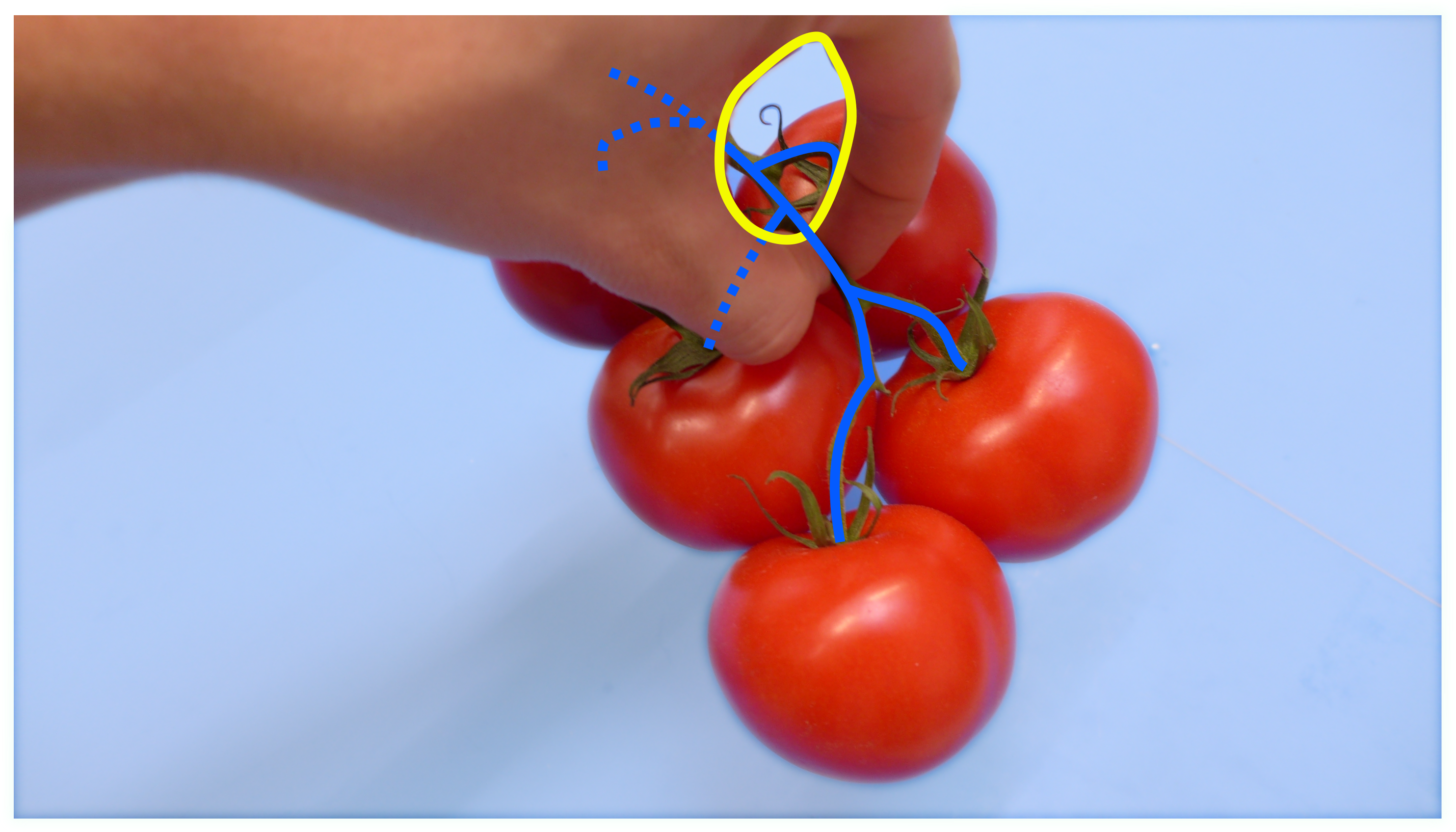
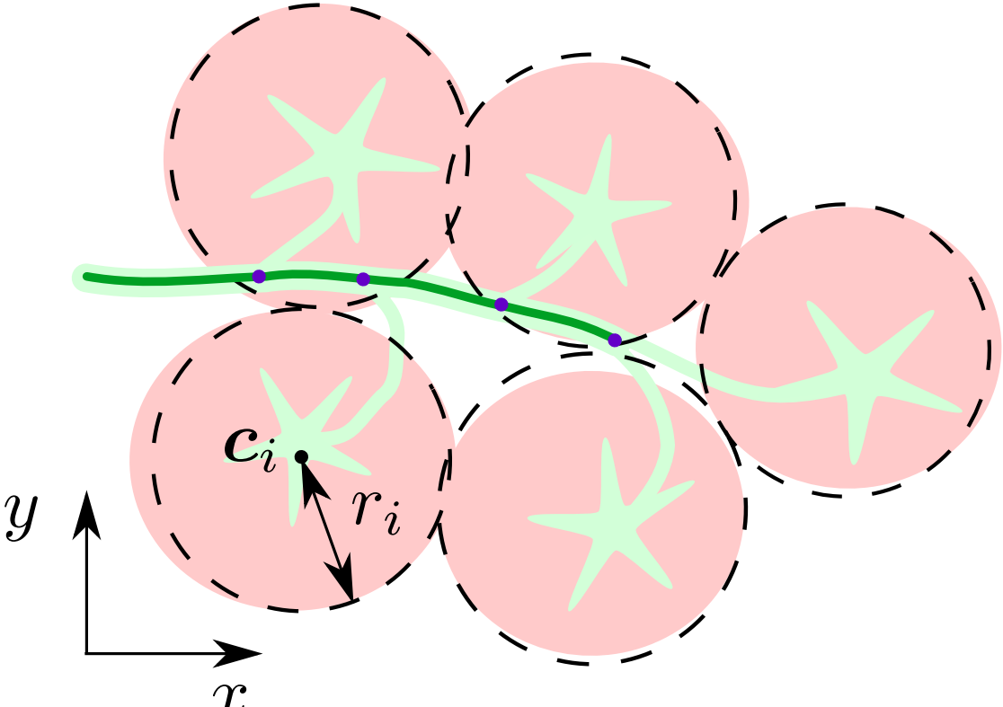
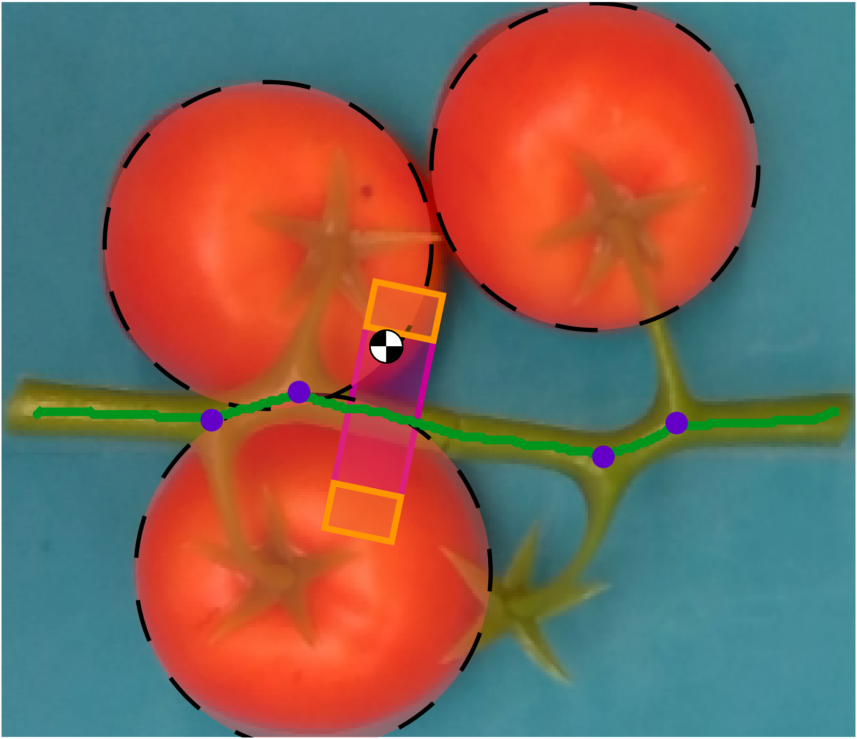
This paper aims to overcome the above limitations by developing a novel geometry-based grasping method for vine tomatoes. We use caging as a grasp method that bounds the target without requiring tight contact between the object and end effector [7]. The general benefits of caging are low mechanical stress applied to the target object, robustness to minor control errors, and no need for force feedback or a mechanistic object model. We apply caging to the stem, using the specific features of its geometry, as illustrated in Fig. 1 and detailed in the sequel.
This work’s main contribution is the development of a vision pipeline to identify a suitable grasping location on the peduncle of vine tomatoes and the subsequent geometry-based grasping approach. We validate the methods by means of lab experiments performed with a low-cost manipulator and an RGB-D camera.
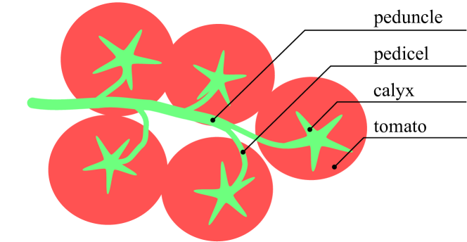
In the sequel, we use the terminology according to Fig. 2. The tomatoes are attached to the stem at the calyx, which is the flower-like structure. They are connected via fruit stalks, called pedicels, to the larger truss stalk called the peduncle. The pedicels are attached to the peduncle at locations which we refer to as junctions.
The rest of this paper is organized as follows: Section II reviews the related work on grasping and peduncle detection of vine tomatoes. Section III presents the computer vision pipeline with the novel peduncle detection method that extracts the required geometric features of the tomato truss. Section IV describes the geometry-based grasping method. Vision and grasping lab experiments and their results are given in Section V and VI, respectively. These results are further discussed in Section VII. Finally, Section VIII concludes this paper.
II Related Work
While significant research has been done on the detection and harvesting of tomatoes [9], only a few works focus on vine tomatoes. Vine tomato trusses cannot be grasped in the same way as single tomatoes, as grasping an entire truss by a single fruit would damage the tomato or detach it from the truss.
II-A Vine Tomato Grasping
The PicknPack project developed a robotized production line to assess the product quality and pack fresh food products such as vine tomatoes [10]. A tomato truss is moved to a location in the harvest crate where the end effector has enough space to apply a pinch grasp on the fruit flesh. However, this way of grasping proved unsuitable, as it causes damage to the tomato skin. Ji et al. [11] designed a harvesting robot for vine tomatoes in a greenhouse environment. After cutting, the truss is pinch-grasped with two rubber-plated fingers at the end of the peduncle. As a result, the grasped truss hangs almost vertically downwards, making accurate placement difficult. Kondo et al. [12] used a similar approach for grasping vine tomatoes.
As an alternative to the pinch-grasp methods, caging can be applied. Varava et al. [8] determined sufficient caging conditions for rigid and partially deformable objects. Caging cannot guarantee a unique pose of the object and can only be used to manipulate objects without stringent precision requirements. To this end, Maeda et al. [13] equipped the end effector with soft pads that deform and apply a small reaction force to the object. Egawa et al. [14] and Kim et al. [15] analytically computed the required gripper distance to cage various rigid and deformable objects, such as two cubes connected via a rope, geometrically resembling a tomato truss.
II-B Stem Detection
Kondo et al. [12] used the HSI (hue, saturation, intensity) color model to detect the connection of a truss to the tomato plant. Yoshida et al. [16] trained a support vector machine on RGB data to separate tomatoes from the background. Individual clusters and a cutting point on the peduncle were identified based on the geometry of the point cloud. Benavides et al. [17] combine edge detection with color-based segmentation to identify both the fruit and truss stem. The PicknPack project developed a vision system to detect vine tomatoes placed in a single non-overlapping layer in blue harvest crates [18]. Tomato trusses are segmented into stem and tomato flesh based on principle component analysis. The peduncle is identified using a random sample consensus (RANSAC) regressor based on the assumption that the peduncle is the longest pixel area present in the stem segment. This assumption does not always hold, causing the peduncle classification to fail.
Recently, deep learning methods have been applied to tomato detection [19]. However, no such methods have been developed for peduncle detection, perhaps because peduncle labeling is much more involved and no suitable data set is readily available for training. Hence, a traditional approach will be followed based on handcrafted features which gives more insight into the problem and allows for tuning by means of easy to interpret parameters.
III Computer Vision Pipeline
The computer vision pipeline extracts the geometric features of the tomato truss from RGB images. A setting is assumed, where a single truss is placed on a blue background with the stem upward. This particular lab setup is chosen to mimic the tomato packaging in a factory setting, where tomato trusses are first singulated and placed on a blue belt. These singulated trusses are later packaged manually. The pipeline steps are image processing, and tomato and peduncle detection, as further detailed below.
III-A Image Processing
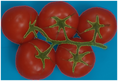
Image processing consists of image segmentation, filtering, and cropping. First, the image is color-segmented such that each pixel is assigned to the background, stem (peduncle, pedicels, and calyxes), or tomato class. The a* color component from the L*a*b* color space and hue color component are computed for an image. The segmentation thresholds have been determined via k-means clustering. Subsequently, small pixel blobs and thin parts are removed using morphological opening and closing. Finally, the image is cropped using a rotated rectangle. The result is illustrated in Fig. 3.
III-B Tomato Detection
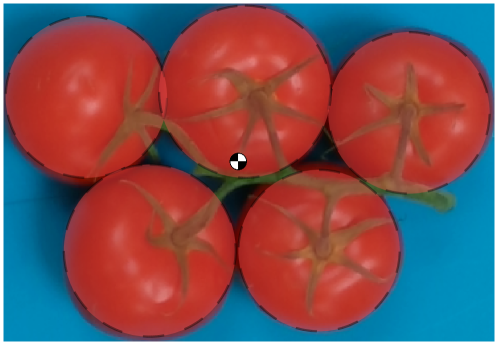
Tomatoes are modeled as circles, whose centers and radii need to be determined. First, the tomato segment edge is determined with the Canny algorithm. Than the circle Hough transform is used to fit circles to these edges. Several parameters are specified, such as the minimum and maximum tomato radius, minimum tomato center distance, resolution of the parameter space for the Hough transform, and sensitivities. False positives are removed by discarding all circles which do not overlap the tomato segment by at least 50%. For each tomato, its center of mass is estimated by assuming that the stem mass is negligible compared to the tomato mass, and that the tomato mass scales with the volume of a sphere with an identical radius [20]. Consider a truss with tomatoes. If the tomato has a center and a radius , then the center of mass of the truss is computed as:
| (1) |
The computed center of mass of the entire truss is later used to determine a suitable grasping point. The result is illustrated in Fig. 4.
III-C Peduncle Detection
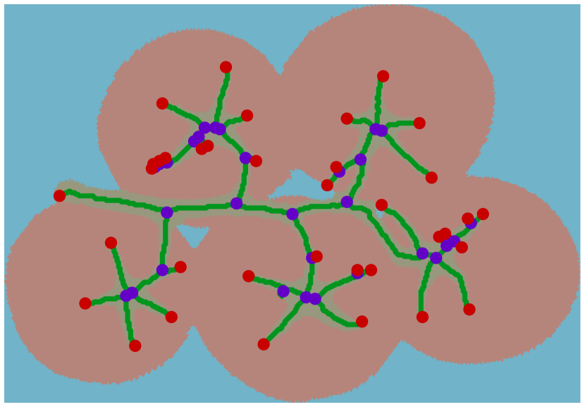
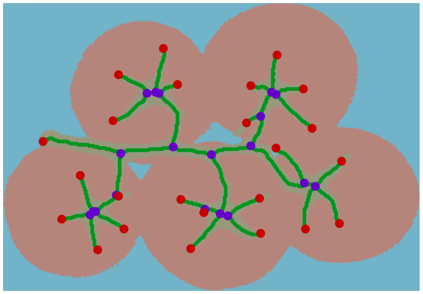
To distinguish the peduncle from the other stem components, a graph-based method is employed. First, a single-pixel-wide representation of the stem segment is computed and then it is converted to a graph. The different stem branches are represented as edges interconnected via vertices. Each vertex is represented by its 2D location on the image. Each edge is associated with a real-valued weight that represents the length measured along the edge. The degree of a vertex is the number of edges incident with this vertex. A vertex is either called a tail when its degree is one, or a junction when its degree is three or more. A truss overlaid with its graph is shown in Fig. 5a. Spurious short edges can result from the stem skeletonization. These are removed by thresholding the junction-tail type edges at a minimum length of 10 mm, as shown in Fig. 5b.
To find the peduncle, we determine the longest path on the graph with a limited curvature. A path is a sequence of alternating vertices and edges, all distinct, and its length is given by the sum of its edges’ lengths. The orientation of an edge is computed using the edge’s source vertex , and the destination vertex as:
| (2) |
Similarly, the orientation of an entire path is computed using the origin and terminus vertex of the path. The curvature between an edge and the path is the absolute difference between their orientations: .
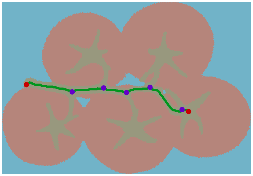
To find the peduncle, the graph is traversed starting from any arbitrary tail vertex towards any other tail vertex. Each newly generated path is compared to the longest path seen so far. If the length of the new path exceeds the length of the longest path, then the longest path is updated. When, at a certain vertex, the orientation between the path traversed so far and the succeeding edge exceeds the threshold of , then the path is split at this vertex. If another succeeding edge that lies within the curvature threshold is found at this vertex, then the original path continues. Otherwise a new path is started from this vertex and the original path is stored if it is longer than the stored longest path. Once this search is performed starting from all tail vertices, the longest path found is the peduncle. The resulting peduncle with junctions and tails is shown in Fig. 5c. Note that a peduncle does not have to be a tail-to-tail path.
IV Geometry-Based Grasping
This section describes a geometry-based grasping method for vine tomatoes. For a successful grasp, we assume that: (i) the truss is placed on a horizontal surface with the peduncle facing upward, (ii) the target truss is separated from other trusses, and (iii) sufficient space is available above the truss for the manipulator to approach it from above.
IV-A Geometric Model of the Vine Tomato
We use a two-dimensional geometric model of the truss and of the end effector to determine a suitable grasp location and gripper orientation. Tomato is modeled as a circle with radius and center , see Fig. 6.
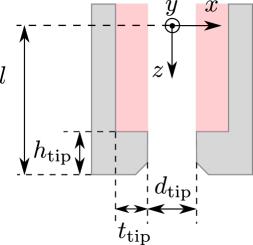
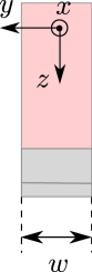
The end effector is a parallel gripper of length and width , see Fig. 7. The fingertips of the L-shaped fingers are of height and thickness . The distance between the finger tips can be controlled. The inner surface of the fingers is covered with soft material to allow for more precise control of the post-grasp truss pose.
IV-B Grasp Constraints
The geometric models are used to derive constraints that represent the caging conditions. Maeda et al. [13] introduced caging-based grasping with deformable parts on the gripper to apply a small reaction force to the object. The following two constraints need to be satisfied for a caging-based grasp:
-
1.
Rigid-part caging condition: the target object is in a complete imprisonment of the rigid parts of the end effector.
-
2.
Soft-part caging condition: assuming that the soft parts of the end effector are rigid, the closed region for caging in the configuration space of the object becomes empty.
The former condition implies that the object cannot escape from the end effector, while the latter condition implies that the soft parts of the gripper deform, and therefore apply a reaction force to the target object. Both conditions can be tested geometrically.
The rigid-part caging condition can be verified by noting that the peduncle exhibits various double fork features, due to the pedicels attached. It is assumed that these features are preserved under deformations of the stem. Therefore, the rigid-part caging condition is met when the end effector encloses a section of the peduncle with junctions on each side. The soft-part deformation condition is satisfied when the diameter of the peduncle is larger than the fingertip distance; this requirement is automatically satisfied when the end effector is fully closed.
To determine a unique target grasp location on the peduncle, we introduce two additional conditions:
-
•
Space condition: the target grasp location lies at least at a distance from the junctions.
-
•
Balance condition: The target grasp location lies as close as possible to the truss’ center of mass.
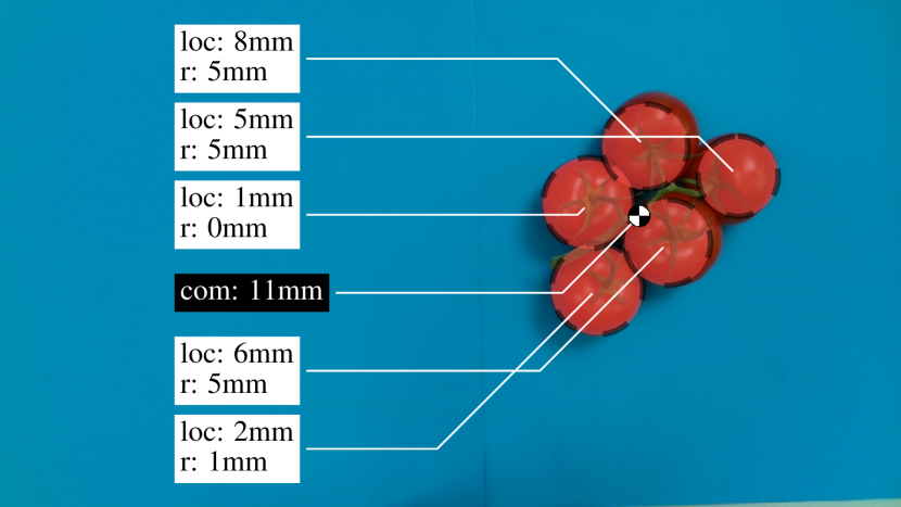
The space condition is introduced such that there is sufficient space for the end effector on the target grasp location. The distance is taken larger than the end effector’s width, to allow for small errors in manipulator control. The balance condition is introduced to prevent undesired tiling of the truss. The selected grasping point is the candidate location which lies closest to the center of mass.
IV-C Grasp Pose
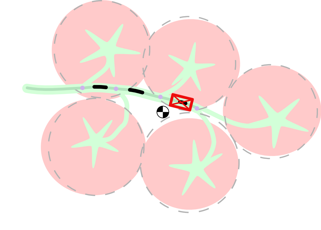
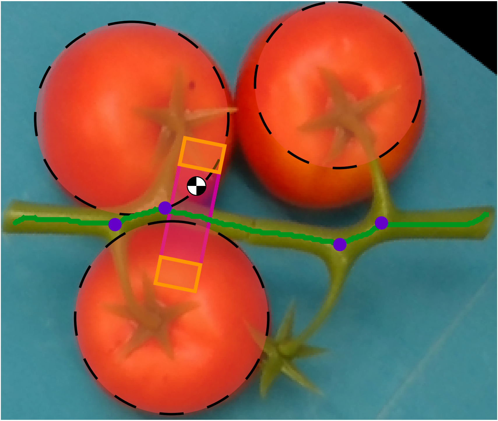
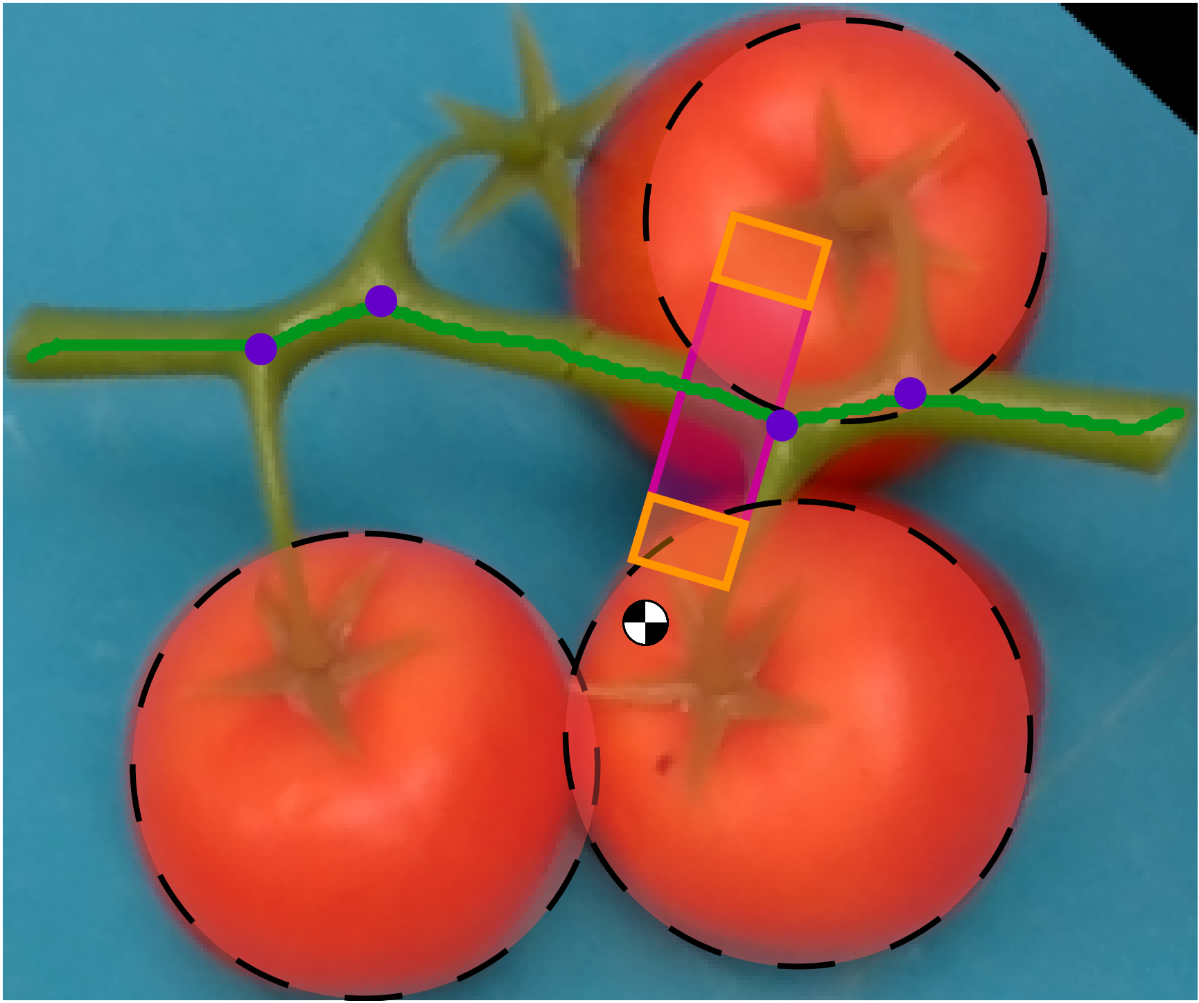
The end effector is aligned with the peduncle. The target grasp pose for the previously discussed truss is shown in Fig. 8. This two dimensional grasp pose is transformed to 3D by adding the grasp height, which is derived from the distance of the peduncle above the surface and the end effector dimensions.
To grasp a truss, the robot’s controller executes the following procedure. First, the manipulator moves to a pre-grasp location which is above the target grasp location. The robot then moves the end effector downward to the grasp pose and closes the gripper. Once the caging-based grasp is accomplished, the robot can lift the truss and place it at a desired location.
V Computer Vision Experiments
The computer vision pipeline was tested on a dataset consisting of 84 labeled images, containing 308 tomatoes and 266 junctions. We counted the number of true positive detections (TP), false positive detections (FP), and false negative detections (FN). The true positive rate (TPR) and false discovery rate (FDR) are computed, which describe the ability of the pipeline to find truss features and its proneness to classify negative examples as positive ones:
| (3) |
Furthermore, the errors of the estimated features are computed and reported as the mean absolute error plus and minus the standard deviation.
V-A Results
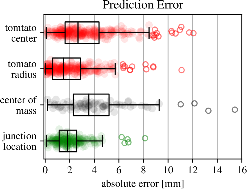
For the tomato detection we obtained a true positive rate of 99.7% (307/308). No false positives were reported. The tomato centers were predicted with an error of 3.58 2.63mm (n=307) and the radii were estimated with an error of 2.43 2.21mm (n=307). As a result, the center of mass is estimated with an error of 5.02 3.26 mm (n=307). For the junction detection, we obtained an overall true positive rate of 86% (229/266) and a false discovery rate of 34% (117/346). The junction locations were predicted with an error of 2.09 1.78mm (n = 229).
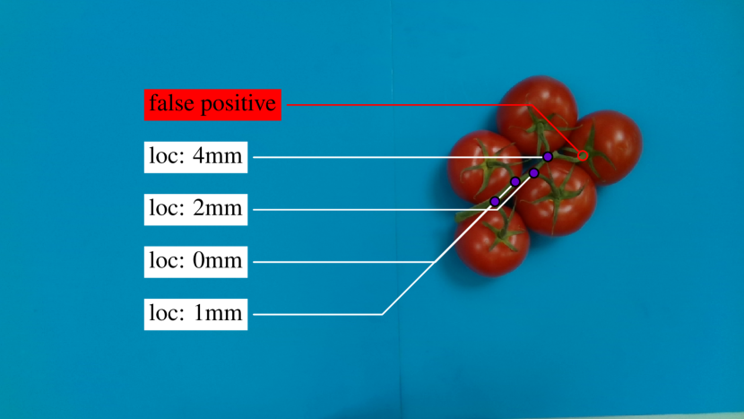
Typical tomato and junction detection results are shown in Fig. 9a and Fig. 9b, respectively. A box plot of the prediction errors for the different truss features is shown in Fig. 10. Based on the obtained features, the algorithm was able to find a target grasp pose on 96% (81/84) of the images. The computer vision pipeline took 1.88 0.83 seconds to execute per image. Peduncle detection, cropping and segmentation take up a significant amount of time.
V-B Discussion
Two factors affect this prediction error. First of all, the tomato features are harder to estimate when a tomato is closely surrounded by other tomatoes or when it is at the edge of the image. For these tomatoes, the circle can only be fitted to a small part of its edge. Secondly, the predictions are affected by the ellipsoidal shape of the tomatoes; sometimes the circle is fitted to a part of the edge which has a smaller or larger radius than the tomato.
The proposed graph-based peduncle search method is able to correctly identify the peduncle in cases where the previously proposed RANSAC regressor fails [18]. The newly developed method works best when the camera is placed directly above the truss, the performance degrades when the object is placed off-center. Many junctions are correctly detected, but also false positives are reported. The junction detection is sensitive to overlapping parts of the stem and to small segmentation errors. Furthermore, the graph-based peduncle search sometimes classifies a pedicel and parts of a calyx as peduncle, resulting in false positives.
VI Robotic Grasping Experiments
We have conducted real-world experiments to validate the proposed geometry-based grasping method for vine tomatoes. These experiments were performed in a lab environment.
VI-A Experimental Setup
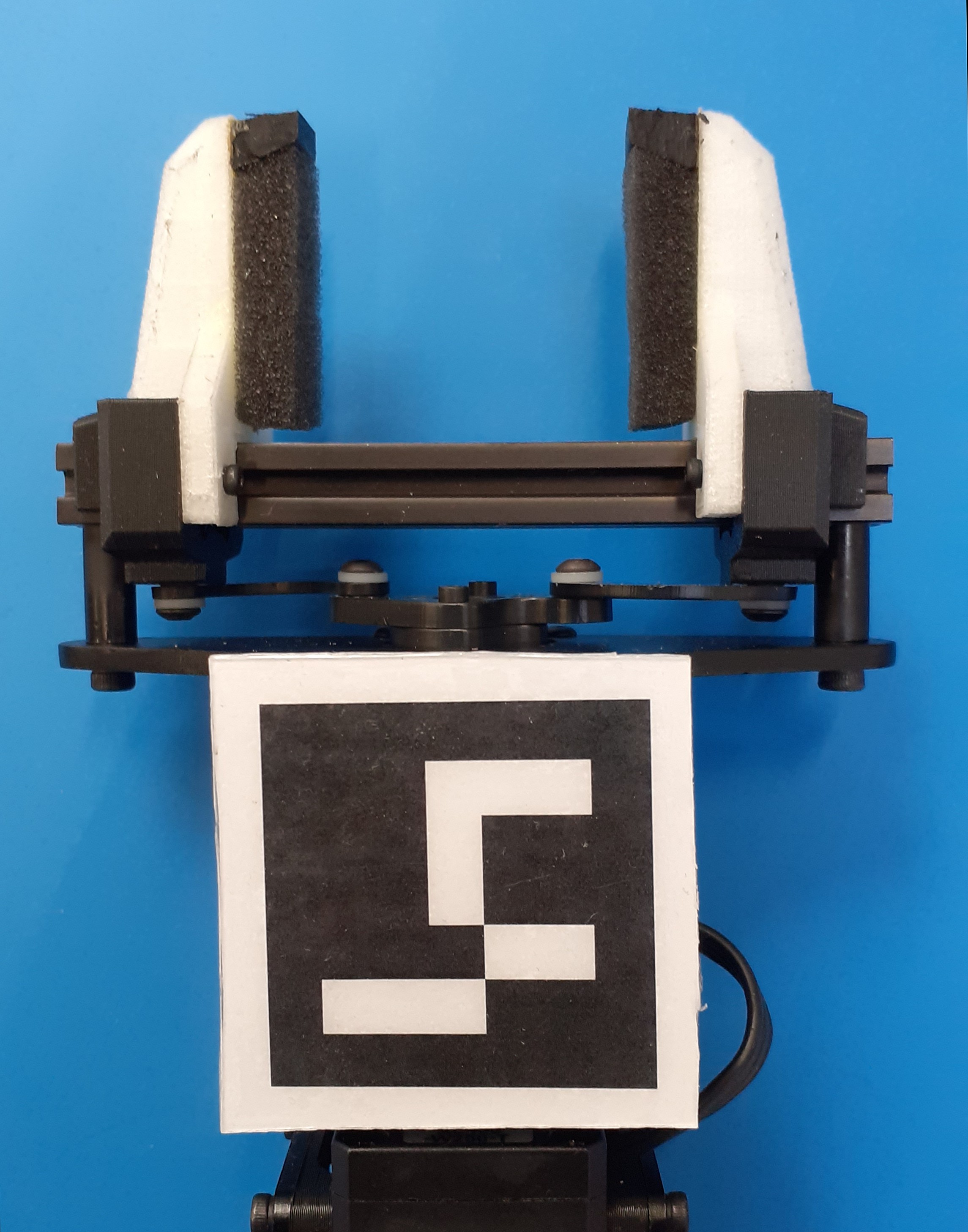
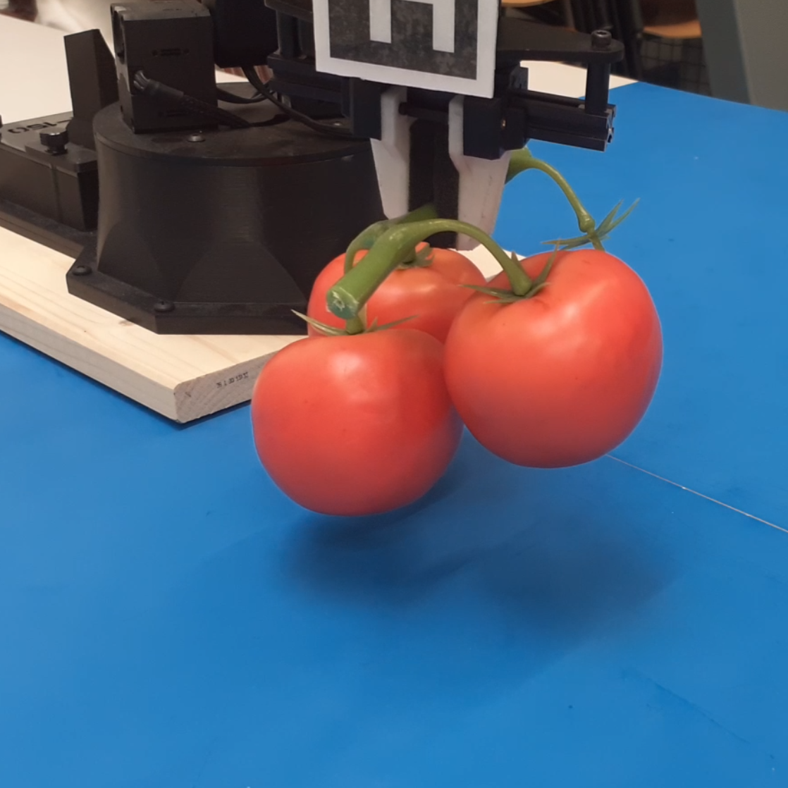
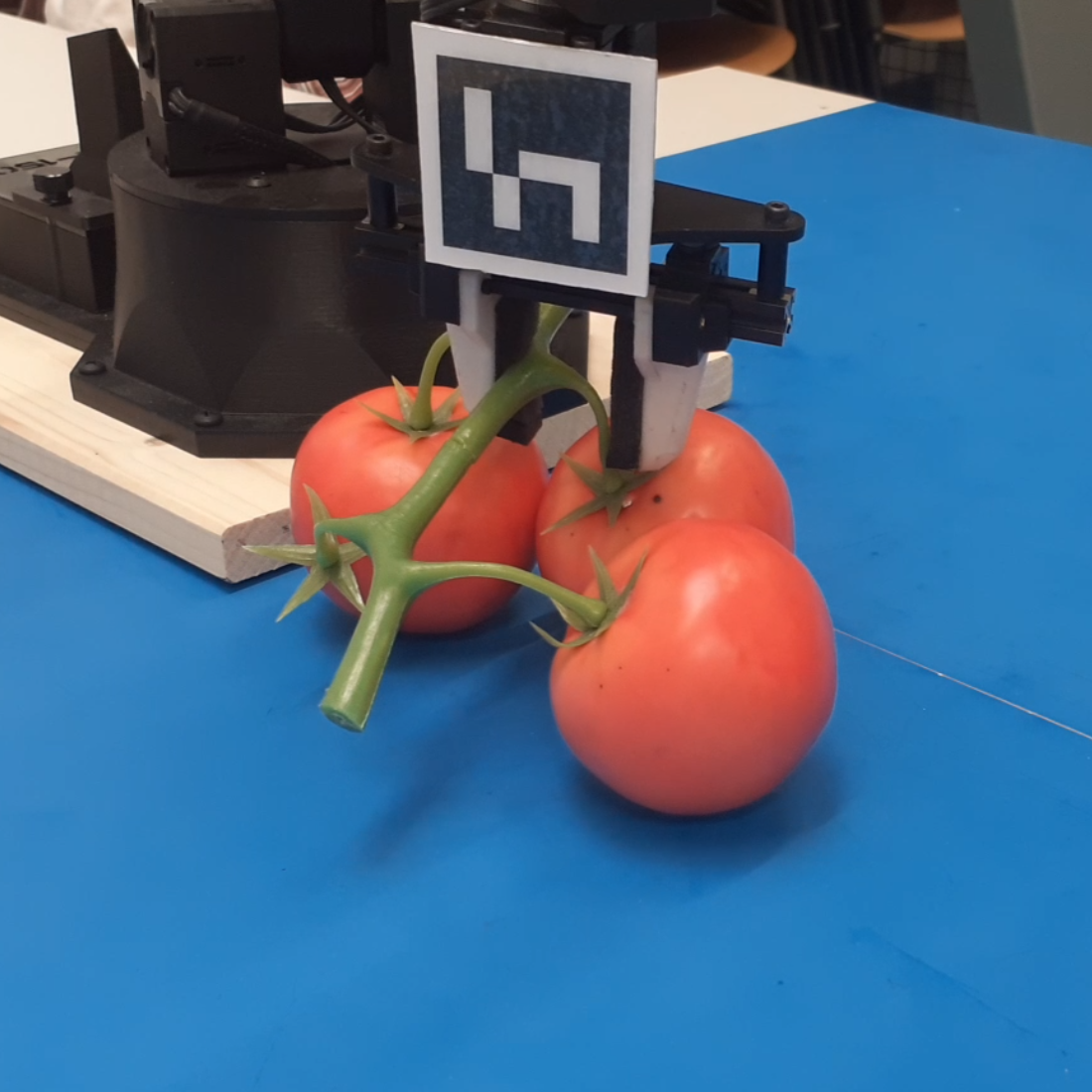
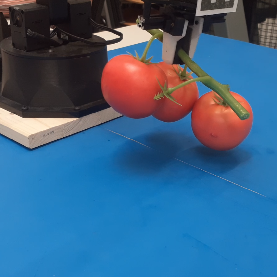
The physical setup consists of a robotic manipulator, an RGB-D vision system and several tomato trusses as shown in Fig. 11a. The Interbotix PincherX 150 Robot Arm has five degrees of freedom555https://www.trossenrobotics.com/pincherx-150-robot-arm.aspx. The gripper fingers are covered with deformable foam as required for the soft-part caging condition. Furthermore, rubber knobs were attached to these fingers such that they can enclose the peduncle. Fig. 11b shows the end effector in its open configuration.
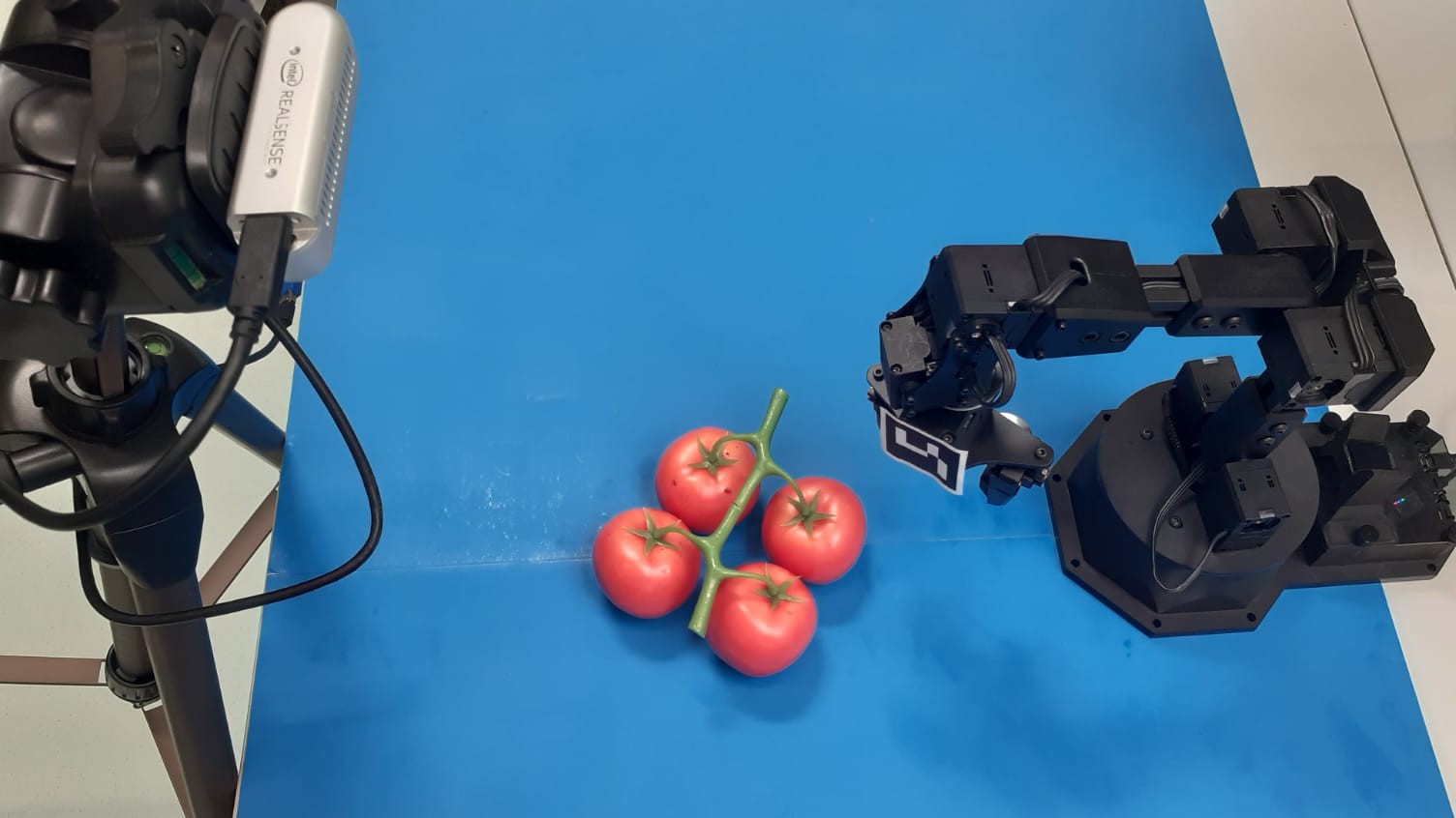
We used the Intel RealSense Depth Camera D435666https://www.intelrealsense.com/depth-camera-d435/ which combines active infra red (IR) stereo technology to measure depth with an RGB sensor for color information. Since a sense-plan-act framework is used, the camera is placed in an eye-on-base configuration. The camera in unable to obtain accurate depth information about the thin peduncle. Hence, the peduncle height is taken as a constant measured before conducting an experiment. Our code is available on GitHub.777https://github.com/padmaja-kulkarni/taeke_msc
Due to the 50g payload limitation of the manipulator, we had to use plastic tomato models. Six trusses of two different categories were created:
-
1.
Simple truss: plastic tomatoes are attached to a plastic peduncle. The peduncle has a relatively large diameter and a simple straight shape.
-
2.
Realistic truss: plastic tomatoes are attached to a real tomato peduncle. Truss stems with sufficient space around the peduncle were selected to accommodate the gripper fingers.
VI-B Task
A pick and place routine is executed to determine the strengths and weaknesses of the method. The task consists of five successive steps: (i) the truss is detected and the relevant features are extracted, (ii) the end effector moves toward the peduncle and grasps it, (iii) the truss is lifted off the supporting surface, (iv) the truss is moved to an arbitrary target pose, and (v) the truss is placed back on the supporting surface. This task is successful if all these parts are completed. The following modes of failure were observed:
-
•
Vision: the vision system fails to identify the key features required for the geometry-based grasping, such as the peduncle, or the junctions.
-
•
Planning: the grasp planning algorithm fails to determine a valid grasp action. For example, it may require a pose that cannot be reached by the end effector due to space constraints. This error indicates weaknesses in the geometry-based grasping method.
-
•
Control: the manipulator fails to execute the planned task. A typical example is the end effector not reaching the target pose. These errors show weaknesses in the hardware, calibration, and control implementation.
-
•
Overload: the hardware fails to execute the task at hand due to overloading or overheating of the servo motors.
In case the task is not successfully executed, the mode of failure will be recorded for later discussion. Since the goal of this experiment is not to test the load capacities of the robot, overload failures will be ignored. When a grasp fails the truss is moved to a new random pose by the human operator such that the next experiment can continue.
VI-C Results
The previously described pick and place routine was executed 20 times per truss, such that the truss is grasped from several different poses. The failure rates are reported in Table I, and typical grasps are illustrated in Fig. 12. Videos taken during the experiment can be found via SurfDrive888https://surfdrive.surf.nl/files/index.php/s/euEKKhtSRqB9mPG and a video attachment is accompanying this paper.
| failure rate (number of failures) | ||||||
|---|---|---|---|---|---|---|
| model id | attempts | all | vision | planning & control | ||
| simple | all |
|
60 | 8% (5) | 3% (2) | 5% (3) |
| 1 |
|
20 | 5% (1) | 5% (1) | 0% (0) | |
| 2 |
|
20 | 20% (4) | 5% (1) | 15% (3) | |
| 3 |
|
20 | 0% (0) | 0% (0) | 0% (0) | |
| realistic | all |
|
60 | 17% (10) | 0% (0) | 17% (10) |
| 1 |
|
20 | 0% (0) | 0% (0) | 0% (0) | |
| 2 |
|
20 | 25% (5) | 0% (0) | 25% (5) | |
| 3 |
|
20 | 25% (5) | 0% (0) | 25% (5) | |
A failure rate of 8% (5/60) was obtained with the simple models. A typical successful grasp is shown in Fig. 12a. From the five failures, two were caused by vision, two by planning, and a single failure was caused by control. For both vision failures, the algorithm was unable to identify the peduncle. In both planning errors, the algorithm did not take into account the surrounding pedicels, causing the end effector to be blocked. An example is shown in Fig. 12b. The last failure was caused by control, where the end effector closed above the peduncle. Most failures occurred on model two, a single failure was made on model one, and no failures were made on model three. Undesired tilting of the second model was frequently observed as shown in Fig. 12c.
On the realistic models, a failure rate of 17% (10/60) was obtained. Twice as many failures were reported compared to the simple models. All ten failures were caused by pedicels blocking the end effector. Four of these cases were caused by planning, and six cases were the result of control. No failures were caused by the computer vision system. All grasp attempts on the first model succeeded, an equal number of failures was observed for models two and three. Most failures on model two were caused by planning, on model three control errors occurred more frequently.
VII Discussion
In the presented experiments, a significant number of errors were caused by the manipulator control. However, not all failures can be attributed to the hardware. For trusses that require more accurate grasping, a significant number of planning errors were made. On the third simple model the center of mass, and thus also the target grasp pose, is close to a pedicel. At such a location small errors in planning result in grasp failure, which explains the lower success rate for this model. The realistic models have less space around the stem, and the pedicels are located closer to each other. This makes the planning and control of a successful grasp more difficult for these models than the simple models.
The grasp pose is determined based on several criteria, among which the space available at the target location on the peduncle. However, it ignores the surrounding stem parts and tomatoes which may block the grasp. The two-dimensional truss model cannot be used to avoid these surrounding objects, as depth information is vital. To make a more appropriate trade-off, the point cloud of the tomato truss should be analyzed instead of computing a target grasp location based on a two-dimensional image. Furthermore, a grasp is always approached in the vertical direction from above as it is assumed that the truss lies on a flat surface. By allowing for different end effector orientations and approach directions, the end effector could grasp the peduncle at previously unreachable locations.
The used experimental method has several limitations. First of all, only a small number of trusses were used. No reliable conclusions can be drawn about the success rate of the proposed method on vine tomatoes in general. Secondly, only truss stems with sufficient space around the peduncle to fit the gripper fingers were used. Trusses exist where the peduncle lies much closer to the tomatoes. For such trusses, the proposed geometry-based method will be much more difficult to apply. Finally, due to hardware limitations, artificial tomatoes were used for the experiments, which may have affected the experimental results.
VIII Conclusion
In this paper, we proposed a geometry-based grasping method for vine tomatoes. This method relies on geometric information and position-based control. A geometric model of the vine tomato and of the end effector was developed. These models were used to verify constraints for a caging-based grasp and to determine a suitable grasp pose. A computer vision pipeline was developed to determine the numerical values of several geometric truss features. Finally, the proposed computer vision pipeline and the geometry-based grasping were tested on a robotic setup.
The computer vision pipeline is able to obtain the key features for trusses of various shapes and sizes. On the test dataset, 99.7% of the tomatoes were correctly detected, without reporting any false negatives. Prediction errors on the tomato locations and dimensions resulted in an error of mm on the truss center of mass. The graph-based peduncle detection method identified the peduncle correctly on trusses for which previously reported methods have failed. The algorithm correctly predicted 86% of the locations where the stem splits, but also 34% false positives were reported. The real-robot experiments show that the newly developed grasping method is capable of grasping vine tomatoes. Experiments were performed on simple trusses with a plastic stem, and on realistic trusses with a real vine tomato stem. On the simple models, 92% of the pick and place attempts succeeded, while on the realistic models, 83% pick and place attempts were successful.
This is a first step in the direction of automating the packaging task of vine tomatoes. Further research is needed to develop extensions required for real-world implementation. Experiments should be performed with high-end hardware and real tomatoes, such that the damage to the crop can be analyzed. The presented method does not take into account the surrounding stem parts or tomatoes when computing a target grasp location. A point cloud of the tomato truss should be used such that these surrounding objects can be avoided. Other extensions are to conduct experiments on a larger batch of trusses and to deal with multiple touching and overlapping trusses.
Acknowledgment
This research is funded by the Netherlands Organization for Scientific Research project Cognitive Robots for Flexible Agro-Food Technology, grant P17-01.
References
- [1] M. Bergerman, J. Billingsley, J. Reid, and E. van Henten, “Robotics in agriculture and forestry,” in Springer handbook of robotics. Springer, 2016, pp. 1463–1492.
- [2] J. A. Foley, N. Ramankutty, K. A. Brauman, E. S. Cassidy, J. S. Gerber, M. Johnston, N. D. Mueller, C. O’Connell, D. K. Ray, P. C. West et al., “Solutions for a cultivated planet,” Nature, vol. 478, no. 7369, p. 337, 2011.
- [3] F. Rodríguez, J. Moreno, J. Sánchez, and M. Berenguel, “Grasping in agriculture: State-of-the-art and main characteristics,” in Grasping in Robotics. Springer, 2013, pp. 385–409.
- [4] H. Lin, F. Guo, F. Wang, and Y.-B. Jia, “Picking up soft 3d objects by feeling when without tactile or force sensing,” 2014.
- [5] L. Zaidi, J. A. Corrales, B. C. Bouzgarrou, Y. Mezouar, and L. Sabourin, “Model-based strategy for grasping 3d deformable objects using a multi-fingered robotic hand,” Robotics and Autonomous Systems, vol. 95, pp. 196–206, 2017.
- [6] J. Sanchez, J.-A. Corrales, B.-C. Bouzgarrou, and Y. Mezouar, “Robotic manipulation and sensing of deformable objects in domestic and industrial applications: a survey,” The International Journal of Robotics Research, vol. 37, no. 7, pp. 688–716, 2018.
- [7] W. Kuperberg, “Problems on polytopes and convex sets,” in DIMACS Workshop on polytopes, 1990, pp. 584–589.
- [8] A. Varava, D. Kragic, and F. T. Pokorny, “Caging grasps of rigid and partially deformable 3-d objects with double fork and neck features,” IEEE Transactions on Robotics, vol. 32, no. 6, pp. 1479–1497, 2016.
- [9] C. W. Bac, E. J. van Henten, J. Hemming, and Y. Edan, “Harvesting robots for high-value crops: State-of-the-art review and challenges ahead,” Journal of Field Robotics, vol. 31, no. 6, pp. 888–911, 2014.
- [10] E. Pekkeriet, “Picknpack; flexible robotic systems for automated adaptive packaging of fresh and processed food products,” European Commission, Tech. Rep., 2016.
- [11] C. Ji, J. Zhang, T. Yuan, and W. Li, “Research on key technology of truss tomato harvesting robot in greenhouse,” in Applied Mechanics and Materials, vol. 442. Trans Tech Publ, 2014, pp. 480–486.
- [12] N. Kondo, K. Yamamoto, H. Shimizu, K. Yata, M. Kurita, T. Shiigi, M. Monta, and T. Nishizu, “A machine vision system for tomato cluster harvesting robot,” Engineering in Agriculture, Environment and Food, vol. 2, no. 2, pp. 60–65, 2009.
- [13] Y. Maeda, N. Kodera, and T. Egawa, “Caging-based grasping by a robot hand with rigid and soft parts,” in 2012 IEEE international conference on robotics and automation. IEEE, 2012, pp. 5150–5155.
- [14] T. Egawa, Y. Maeda, and H. Tsuruga, “Two-and three-dimensional caging-based grasping of objects of various shapes with circular robots and multi-fingered hands,” in IECON 2015-41st Annual Conference of the IEEE Industrial Electronics Society. IEEE, 2015, pp. 000 643–000 648.
- [15] D. Kim, Y. Maeda, and S. Komiyama, “Caging-based grasping of deformable objects for geometry-based robotic manipulation,” ROBOMECH Journal, vol. 6, no. 1, p. 3, 2019.
- [16] T. Yoshida, T. Fukao, and T. Hasegawa, “A tomato recognition method for harvesting with robots using point clouds,” in 2019 IEEE/SICE International Symposium on System Integration (SII). IEEE, 2019, pp. 456–461.
- [17] M. Benavides, M. Cantón-Garbín, J. Sánchez-Molina, and F. Rodríguez, “Automatic tomato and peduncle location system based on computer vision for use in robotized harvesting,” Applied Sciences, vol. 10, no. 17, p. 5887, 2020.
- [18] E. Pekkeriet, “D5. 3 report on robot performance and lab test results,” EU, Tech. Rep., 2015.
- [19] G. Liu, J. C. Nouaze, P. L. Touko Mbouembe, and J. H. Kim, “YOLO-Tomato: A robust algorithm for tomato detection based on YOLOv3,” Sensors, vol. 20, no. 7, 2020. [Online]. Available: https://www.mdpi.com/1424-8220/20/7/2145
- [20] I. Nyalala, C. Okinda, L. Nyalala, N. Makange, Q. Chao, L. Chao, K. Yousaf, and K. Chen, “Tomato volume and mass estimation using computer vision and machine learning algorithms: Cherry tomato model,” Journal of Food Engineering, vol. 263, pp. 288–298, 2019.