44email: lastname@lakeside-labs.com 55institutetext: Gianluca Prato 66institutetext: LINKS Foundation, Turin, Italy
66email: gianluca.prato@linksfoundation.com 77institutetext: Etienne Brosse 88institutetext: Softeam Research and Development Department, Paris, France
etienne.brosse@softeam.fr 99institutetext: Omar Morando 1010institutetext: Digisky, Turin, Italy
1010email: morando@digisky.it
Engineering Swarms of Cyber-Physical Systems with the CPSwarm Workbench
Abstract
Engineering swarms of cyber-physical systems (CPSs) is a complex process. We present the CPSwarm workbench that creates an automated design workflow to ease this process. This formalized workflow guides the user from modeling, to code generation, to deployment, both in simulation and on CPS hardware platforms. The workbench combines existing and emerging tools to solve real-world CPS swarm problems.
As a proof-of-concept, we use the workbench to design a swarm of unmanned aerial vehicles (UAVs) and unmanned ground vehicles (UGVs) for a search and rescue (SAR) use case. We evaluate the resulting swarm behaviors on three levels. First, abstract simulations for rapid prototyping. Second, detailed simulation to test the correctness of the results. Third, deployment on hardware to demonstrate the applicability. We measure the swarm performance in terms of area covered and victims rescued. The results show that the performance of the swarm is proportional to its size. Despite some manual steps, the proposed workbench shows to be well suited to ease the complicated task of deploying a swarm of CPSs.
Keywords:
Cyber-physical system (CPS)behavior engineering swarm modeling code generation swarm intelligence search and rescue (SAR).1 Introduction
Developing software to control an individual cyber-physical system (CPS) or even a system of CPSs is challenging in multiple ways. First, CPS setups typically involve wildly different pieces of hardware running on different platforms (44) with different constraints and requirements. Second, CPSs are equipped with multiple sensors and actuators to link the physical world with a virtual one (43). Third, CPSs are highly connected and thus show a high degree of interaction between individual entities (56) introducing challenges for communication and coordination. Such highly-networked systems become increasingly hard to design which may lead to unpredictable behavior (29).
A possible approach to design and develop such a system of CPSs is to use the inspiration of swarm intelligence (5) where every autonomously acting CPS is a member of a large swarm of CPSs. Each swarm member follows a set of local rules that globally leads to emergent swarm behavior. The concept of swarm intelligence is exemplified by swarm robotics (46) which is a research direction that applies swarm intelligence to groups of robots. In this work we generalize this approach from robotics to CPSs.
Engineering swarm intelligence algorithms for CPSs is very challenging as the desired global swarm behavior is hard to predict from the local rules of the individual CPSs (1). In this work we take a bottom-up approach to iteratively design the CPS controllers that yield the desired swarm behavior. This is achieved through simulation experiments modeled on different levels of abstraction (42). Hence, a well-defined model of the CPSs and the desired local behavior is required that can be scaled to the different abstraction levels (30). Such a multi-scale model needs to take into account the engineering of both hardware and software components of the CPSs as well as the composition of the whole swarm.
Therefore, we propose a model-driven engineering process that starts from modeling the CPS hardware and behavior and results in behavior code that can be deployed to and executed on the CPSs. The process is based on a hierarchically organized set of behaviors that together build the complete controller of a single CPS. Together with a well-defined library of behavior models, an automated code generation process allows to assemble the behavior of the CPSs in the form of executable code. Based on the multi-scale modelling approach, it is possible to validate the swarm behavior. This is achieved by an abstract simulation that is used for rapid prototyping of the CPS behavior resulting in the desired swarm behavior. For verification purposes, it is then qualitatively compared to the behavior resulting from the code generation process using a detailed simulation. These results are used to verify that the model and the generated code yield the behavior previously observed with an abstract simulation. The resulting behavior is demonstrated on hardware in the form of a proof-of-concept.
To prove the practicability of this engineering process, we base our experiments on a search and rescue (SAR) scenario. This use case envisions a heterogeneous swarm of unmanned aerial vehicles (UAVs) and unmanned ground vehicles (UGVs) that is deployed in a highly dynamic disaster environment to support first responders in real-time. Its mission is to collectively search for victims (UAVs), and rescue them (UGVs). Such a mission is well suited for testing swarms of CPSs because it can benefit from several swarm properties. The scalability of a swarm allows to add more CPSs during the mission in case the area to be covered is larger than expected. The robustness of a swarm takes into account challenging environments where individual CPSs can fail. Moreover, in contrast to fully centralized control, such a swarm can still operate even if connectivity is sparse. The swarm operates autonomously as a self-organized mixed team where the decisions to fulfil the mission are made as appropriate and demanded from the dynamic environment.
This work is part of the CPSwarm project (4). It aims at developing a tightly integrated toolchain that covers the whole design process of CPS swarms, starting from modeling and code generation to deployment, running, and monitoring the swarm in simulations and real-world scenarios. This is enabled by the CPSwarm workbench (24), a toolchain that has been established to serve as a glue among the individual components in a CPS design process (20). In this paper we highlight parts of this toolchain including modeling, code generation, and execution of the swarm applied to the SAR use case. For further details on the workflow, the reader is referred to (4).
Our main contributions are:
-
•
We formalize the engineering process of designing a swarm of CPSs.
-
•
We provide a set of tools that are tightly linked to allow CPS software development.
-
•
We provide a library of functions and behaviors to speed up the process of CPS swarm software development.
-
•
We demonstrate the complexity of the engineering process that arises from the deployment onto a swarm of CPS hardware platforms.
After reviewing the state of the art in Section 2, we provide a description of the proposed engineering process in Section 3. We then exemplify this methodology on the SAR use case in Section 4. To complete the process we perform an evaluation of the resulting behavior in Section 5 that is used to validate the process. We conclude the paper in Section 6.
2 Related Work
The CPSwarm toolchain is dedicated to the design process of CPSs with a focus on a swarm applications. A very similar approach taken by the OpenADx working group 111https://wiki.eclipse.org/OpenADx, which aims at developing a toolchain that targets autonomous driving use cases. It is developed as open source project within the scope of the Eclipse Foundation and comprises similar design steps, namely architecture definition, simulation, integration, test drives, and connectivity-based validation. The initiative spans across multiple industries and started in 2019, thus the toolchain is conceptually on a very early stage. To the best of our knowledge, this is the only other toolchain that integrates the complete design cycle of CPS development.
2.1 Hardware Modeling
Modeling CPS hardware allows to focus on the application by reducing complexity. In the scope of this paper, we work with the concepts of model based system engineering (MBSE). Models are created with use-case-specific requirements including functional, performance, and interface requirements (18). This allows to design a system by concentrating knowledge and guiding the implementation process.
The INTO-CPS project focuses on MBSE for CPS (28). It employs several tools to cover the entire modeling life cycle. Besides sensors and actuators, its CPS model consists of the behavior that is modeled as additional “hardware” component. This allows sensors and actuators to directly interact with the core behavior. The OpenMETA project follows a similar approach (55). It provides a model and component-based design toolchain for complex CPSs that supports model, tool, and design process integration. The CERBERO project (32) has a cross-layer model-based approach to describe, optimize, and analyze energy efficient and secure CPSs focusing on adaptivity. It uses data models that allow reconfiguration at runtime. A comprehensive overview of modeling technologies for CPSs is given in (39). Hardware models may also be combined with behavior models as proposed in (16).
Our work applies MBSE approach proposed in the INTO-CPS project. We extend the existing work by allowing to model not only the hardware composition of a CPS, i.e., the sensors, actuators, and controller, but also the composition of a swarm of CPSs. The swarm composition describes the type and cardinality of CPSs included in the swarm.
2.2 Behavior Modeling
The behavior of swarm agents is typically modeled by textual and mathematical formulations (21; 22; 61), pseudo code (35), or diagrams (21). Especially the latter is experiencing a high popularity since diagrams can be represented both visually to be read by humans and formally for automatic processing. A prominent example are finite state machines (FSMs) which have been used to model the behavior of individual robots (7; 2), networked systems (54), multi-robot systems (41), and swarm robotic systems (53). Other approaches go further by defining a new language for specific purposes. For example, Modelica is a language for modeling and simulation of physical systems (19). It has been applied to CPS simulation in (23). The behaviour-data relations modeling language (BDRML) introduced in (38) focuses on modeling the information exchange between robots in a swarm.
More recently, behavior trees (BTs) have been adopted from the game industry and applied to swarm robotics behavior modeling (9; 27). They pick up the idea of the subsumption architecture (7) which proposes several abstraction layers to simplify the design process. This approach is similar to our proposal of hierarchical FSMs with the main difference that behaviors are assembled from tasks rather than states.
A less formal approach are design patterns that have been successfully instrumented for taking design decisions in recurring problems. Design patterns are developed over time by a community of experts. They are usually formulated in prose to avoid specific vocabulary and to keep the formulations understandable for all stakeholders that are involved in the design process. Recent research takes into account semi-formal and formal approaches in order to automate the structuring, retrieval, and selection processes for patterns using specific libraries (11; 13). Similarly, other types of formal behavior models can be placed in libraries (33). This enables their reuse and the creation of new behaviors by combining existing models (12; 15).
However, a common representation for swarms of CPSs is still missing. Therefore, we propose a modeling approach that is flexible enough to feature different complex scenarios using different types of hardware. This approach builds on the well established concepts of unified modeling language (UML), systems modeling language (SysML), and FSMs to increase the acceptance.
2.3 Code Generation
Code generation can be tackled on multiple levels. Most commonly, a template based code generation (25) is used which enables generation of executable code from behavior models based on pre-defined templates. In the domain of CPSs, there are approaches for automated controller synthesis (45; 31) which generate complete CPS controllers from abstract CPS models. Furthermore, there are approaches that provide comprehensive tool chains to integrate the modeling and CPS controller synthesis (8; 28).
The CPSwarm workbench provides a step forward in terms of simplification and correct code generation of CPS behavior, enabling an almost fully automated approach that avoids the introduction of errors in manual implementation of CPS behavior software. The CPSwarm code generator does not aim to substitute developer work but to support the development by simplifying the process of integrating CPS swarm modeling with the deployment of CPS controllers. In particular, this objective is achieved by integrating the template based code generation techniques with an abstraction layer into the CPSwarm workbench.
3 Engineering CPS Swarms
Engineering a swarm of CPSs comes with a number of decisions. This includes (i) deployment specifics such as number, type, and placement of CPSs, (ii) hardware of individual CPSs, e.g., communication interface, on-board sensors, or battery dimensioning, and (iii) required behavior of individual CPSs and the CPS swarm. In this section we describe our engineering process including CPS modeling and automatic CPS code generation for simulation and deployment. This process is visualized by the activity diagram in Figure 1.
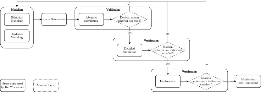
It is supported by the CPSwarm workbench whose architecture is visualized in Figure 2.
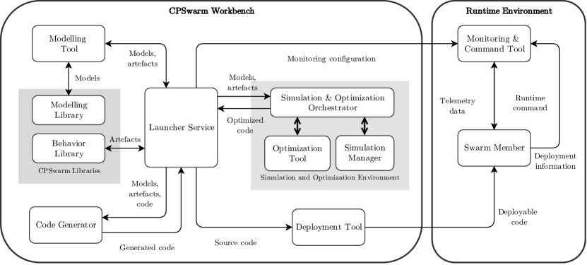
The architecture diagram shows the actual interconnections between the different tools that are used at each step. It can be seen that all data is passed through and handled by the central launcher. All tools of the workbench are released as open source software packages in the CPSwarm GitHub repository 222https://github.com/cpswarm/workbench. In the following we discuss modeling and code generation. The validation and verification process is detailed in Section 5.
3.1 Hardware Modeling
One main aspect of modeling a CPS consists of specifying its architecture in terms of hardware components and their interactions. We build the hardware models using SysML (3). It extends UML by putting a focus on modeling systems with block diagrams. To enable modeling of CPS swarms, we built a CPS swarm profile (48) extending the block definition diagram (BDD) and internal block diagram (IBD). It includes three types of diagrams:
-
•
The swarm composition diagram extends the BDD that allows to model the swarm as a whole. It specifies the types and number of CPSs used in the swarm.
-
•
The hardware composition diagram extends the BDD to model the individual hardware components used by the CPSs. It specifies which types of hardware components exist and defines their parameters such as inputs and outputs.
-
•
The swarm member internal diagram extends the IBD to model the structure of a single CPS. It specifies how the behavior algorithms can interact with the world by defining sensors, actuators, and communication interfaces. Where sensors are inputs to collect information from the environment and actuators are outputs to interact with the environment, a communication interface can be both input and output to the swarm algorithms and enables coordination between CPSs.
3.2 Behavior Modeling
The behavior models define the software components of each CPS. They are modeled to describe how the CPS behaves by interacting with the environment and the other CPSs in the swarm. The behavior is defined in a way that the CPS swarm executes and completes the mission that is intended by the designer of the swarm system. Designing the behavior of individual agents in a swarm is a difficult task because the emergent swarm behavior is not easily predictable (1). Modeling the behavior on an abstract level facilitates the process by allowing to execute it on different levels of realism. This bottom-up approach allows to iteratively refine the individual behaviors until a global swarm behavior is reached. The formal behavior models allow to speed up the design process by automatically generating the code to be executed on the CPSs, either in simulation or in real-world experiments.
3.2.1 Behavior State Machines
A mission for a swarm of CPSs typically requires many different behaviors to be executed by the CPSs to complete the different tasks of the mission. These individual behaviors can be simpler to describe and implement, and are regarded to be atomic during modeling. Combining these simple behaviors into more complex behaviors allows to achieve complex missions. A commonly used approach for this are FSMs, where the states correspond to simple behaviors and the FSM describes a complex behavior. Each CPS can execute an FSM while always being in a defined state which can vary between CPSs. Hence, complex swarm configurations can emerge where CPSs take on different roles based on their interactions.
The transitions between behavior states are triggered by events that can either originate locally, e.g., from sensor readings or behavior rules, or remotely, e.g., from communication between CPSs or commands from a control station. Exchanging events between CPSs enables the coordination of the swarm behaviors. The way events are processed locally is done autonomously by each CPS and defined in the behavior FSMs. This allows CPSs to influence each other’s behavior changes by exchanging events. Events are formalized by a unique identifier (ID), a timestamp, and a unique ID of the sender. Furthermore, events can have data associated with them that is passed among behaviors.
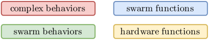
The behavior FSM model is based on the UML behavior FSMs (10). Specifically, the simple behaviors are modeled by simple states and the complex behaviors are modeled using composite or submachine states. Composite states allow a state to be modeled by another FSM whereas submachine states allow to encapsulate generic FSMs that can be reused within more than one state. In the context of CPS swarm behaviors, we propose four different behavior types (the color codes refer to the ones used in Figure 3):
-
•
Complex behaviors (red) are defined by an FSM of simple behaviors, e.g., SAR.
-
•
Swarm behaviors (green) are simple behaviors that execute a specific swarm algorithm exhibiting an emergent swarm behavior, e.g. aggregation or exploration.
-
•
Swarm functions (blue) are simple behaviors that execute a single function including the interaction between CPSs, e.g. task allocation or exchanging position information.
-
•
Hardware functions (yellow) are simple behaviors that execute a single function including hardware interaction, e.g., moving to a given location or controlling an actuator.
The behaviors are formalized by a unique name, a short description of the behavior, the behavior type, and the inputs and outputs of the behavior.
In related literature there typically does not exists such a fine grained distinction between different behavior types. For example, swarm behaviors and swarm functions are termed collective behavior in (6) and basic swarm behavior in (50). In (17), constituent behavior is used as a term for any kind of simple behavior including hardware functions. We deliberately introduce the distinction between the behavior types in order to foster clean and structured design of the behavior FSMs. This is enabled through hierarchically nested states as defined in the UML standard. This allows to abstract behavior details at higher levels. For example, an aggregation behavior can thus be implemented agnostic to the way position information is exchanged between CPSs. Events can either trigger a state change of the sub FSM or force the higher-level behavior itself to terminate and thereby also terminate the currently running sub behavior.
3.2.2 Behavior Libraries
The behaviors are placed in libraries to allow frequently recurring behaviors and functionalities to be defined only once. We propose the library structure shown in Figure 3 where the colors represent the different behavior types previously introduced.
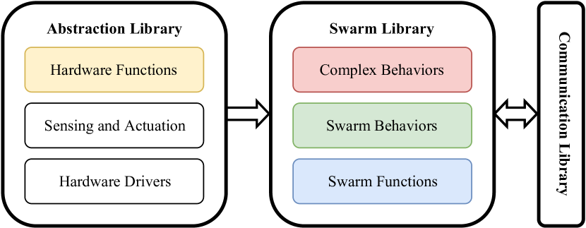
These libraries are structured according to the level of hardware abstraction to enable a separation of concerns. They contain software artifacts that are modeled as states of the FSMs. The Swarm Library works independently of the underlying hardware. It provides the complex behaviors modeled as FSMs together with the swarm behaviors and swarm functions. It makes use of a Communication Library that provides an interface for communication among CPSs. The Abstraction Library abstracts away the hardware specifics. It provides functions that are related to the hardware and functionalities to access sensors and actuators based on hardware specific drivers.
The Swarm Library
contains the swarm behaviors executed by the individual CPSs leading to the global behavior of the swarm. They are platform independent and thus can be reused among different types of CPSs. The Swarm Library is structured into three sub libraries in accordance with the previously introduced swarm behaviors. First, the Complex Behaviors library contains the FSMs that model the complex, high-level mission behaviors such as SAR. They are defined as UML composite or submachine states. Second, the Swarm Behaviors library contains individual swarm algorithms that exhibit an emergent behavior. Typically, such swarm algorithms are handcrafted based on biological inspiration or generated automatically, e.g., using evolutionary optimization. Examples are flocking, phototaxis, or collective transport. They are defined as UML simple states to be used in the complex behavior FSMs. Third, the Swarm Functions library contains simple swarm related tasks. These are tasks that do not lead to an emergent behavior but rather are used to enable the functioning of the swarm behaviors. Examples are exchange of position information, task allocation, or computing the average velocity of the swarm. They are defined as UML simple states to be used in the complex behavior FSMs.
The Communication Library
provides communication services to the swarm that are built on an arbitrary network interface. These services include transmission of telemetry from CPSs to the command and control station, exchange of events between CPSs and between CPSs and the command and control station, and remote access to parameters of the CPSs in the swarm. The Communication Library developed as part of this work is released on GitHub333https://github.com/cpswarm/swarmio.
The Abstraction Library
allows to access the hardware of the CPS. It raises the level of abstraction from a platform-dependent point of view to an application-oriented perspective to facilitate the development of high-level routines. This allows to concentrate on describing how the CPSs should behave in order to complete a high-level task or reach an application-specific goal. This is achieved by providing a set of CPS-specific libraries in order to access platform-specific information of a CPS in a standard and coherent way.
To achieve this, the Abstraction Library is organized as a composition of three layers where each layer adds a level of hardware abstraction. First, the bottom most layer of Hardware Drivers gathers the software libraries that are responsible for enabling the other layers to access the hardware functionalities. This layer constitutes the foundation of the Abstraction Library and includes all the drivers for sensors and actuators that are mounted on the CPSs. Second, the Sensing and Actuation layer is responsible for providing sensor information and for controlling the CPSs using their actuators. While the Hardware Drivers layer has a direct connection with the hardware, this layer purely consists of software that contributes to supply a first degree of abstraction by realizing complex functionalities required by the overlying layer. Finally, the topmost layer of Hardware Functions exhibits a set of high-level functions corresponding to complex routines that a CPS can execute involving a set of sensors and actuators. Each function interacts with the lower layers for sending actuator commands and requesting sensor information. These functions constitute the base building blocks to define the states of the FSMs as UML simple states.
3.3 Code Generation
The code generator is responsible for transforming the FSM models into code that can be deployed and executed on the CPSs. The generation is template-based which is well suited for such schematic and repeatable structures. Template-based generation defines a simple set of target-templates to be filled with data extracted from the algorithm specification.
These templates are text files, composed of a static part that appears one-to-one in the output and a dynamic part replaced by input data, written in a template meta-code. This code contains all the directives that are processed together with the input data by a template engine to produce the final source code. Different templates allow to target different runtime platforms. A set of templates to generate executable code is realized using the velocity template language (VTL).
The data that is processed by the code generator to produce the output are the FSM models of the complex behaviors. When the modeling phase is completed, the resulting FSM is translated to a state chart XML (SCXML) file. The resulting file contains all the information needed by the code generator to complete its task. In particular, it contains the information related to the type of the functionality that is used to select the correct template during the generation process. Furthermore, it contains the definition of the application programming interface (API) of the corresponding functionality that is executed in a specific state.
Using the SCXML file and the set of templates, the code generator can produce Python code, implementing the designed FSM using the SMACH library. SMACH is a Python-based project, that allows easy implementation and execution of FSM-based algorithms. The code generator developed as part of this work is released on GitHub444https://github.com/cpswarm/code-generator.
4 Use Case: Search and Rescue
In this section, we demonstrate the previously proposed formal approaches using a heterogeneous swarm of CPSs. We describe how we model the hardware and software components that are used for the experimental evaluation. The focus is to demonstrate the feasibility of deploying the software onto CPSs from the models. We use the modeling tool Modelio to create these diagrams and then export the data to be further processed by the code generator using the CPSwarm Modeler module555https://github.com/cpswarm/modelio-cpswarm-modeler.
For this demonstration, we choose the use case of SAR. In such missions, CPSs can be used for multiple tasks including creation of a situational overview, logistic support, acting as repeater or surrogate for other CPSs, and removal of rubble (34). As our focus is on the demonstration of the workbench including deployment on hardware platforms, we simplify the SAR scenario in such a way that it can be accomplished with prototype platforms that do not require specialized hardware. Hence, the tasks to be completed by the CPSs is finding human casualties or persons trapped in the disaster site and delivering first aid. We implement the heterogeneous swarm using UAVs and UGVs. The mission of the CPSs swarm can be described as follows: the UAVs cover a defined environment searching for victims while the UGVs stay idle. Once a UAV discovers a victim, it switches from coverage to tracking. It continuously tracks the victim position which it communicates to the UGVs. To select the most appropriate UGV to reach the victim, the UAV starts an arbitration process. The UGV is selected based on a cost value submitted by the UGV, e.g., the distance to the victim. The selected UGV navigates to the victim using the position received from the UAV. After having reached the victim, the victim is assumed to be rescued, the UGV returns to its starting position, and the UAV restarts the coverage process to find a new victim.
In the following we focus exemplarily on modeling the UAVs, i.e., the hardware models and the behavior implementation which is based on robot operating system (ROS) (40). We omit the simpler UGV models for the sake of saving space. We slightly abstract the SAR use case by referring to victims as targets.
4.1 Hardware Models
The hardware platforms used in this work are prototype platforms. The UAV platform is custom made by the authors. The UGV platform is based on an off-the-shelf radio control (RC) truggy. The extended SysML IBD model corresponding to the UAV prototype platform is shown in Figure 4.
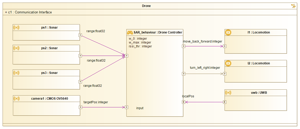
The model specifies inputs (sonar range finders, camera, and ultra-wideband (UWB) localization), outputs for controlling the locomotion, and a communication interface for communication between the CPSs and the command and control station. Details about this modeling process can be found in (47).
4.2 Behavior Implementation
To model the behavior of the UAVs, we use a two-leveled FSM hierarchy . It models the swarm behaviors using a set of swarm and hardware functions from different libraries. The implementation of the behavior libraries is based on ROS which is an open-source framework to ease the development of robot software. It is currently considered a de facto standard in the robotic community because of its great flexibility and support for a wide variety of hardware platforms.
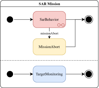
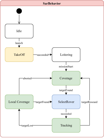
The first level in the hierarchy , describes the set of parallel processes executed on each UAV shown in Figure 5a. The actual SAR behavior to accomplish the mission is modeled by the SarBehavior state. It is a complex behavior modeled as FSM. The missionAbort event allows to directly terminate the execution of the SarBehavior, including any behavior currently running in the corresponding FSM. Hence, an event broadcast by the command and control station to all CPSs allows to completely stop the mission. There are several swarm functions and hardware functions running in parallel. They are detailed in the Tables 1 and 2, respectively.
The second level in the UAV FSM hierarchy describes the SAR behavior executed by each UAV. It is modeled by the FSM shown in Figure 5b. After switching on a UAV, it is in the Idle state. The event launch emitted by the command and control station switches the UAV to the TakeOff state where it lifts off. This function succeeds once the UAV is at the desired altitude transitioning to the Loitering state in which the UAV hovers stationary. The SAR mission itself is started with the missionStart event. The SAR behavior starts with the Coverage state in which the UAV searches for targets. If a target is found, the TargetMonitoring triggers the targetFound event letting the UAV switch to the SelectRover state. The UAV communicates with all available UGVs to select the closest UGV for moving to the target. While the selected UGV moves towards the target, the UAV performs the Tracking behavior to not lose the target until it is reached by the selected UGV. It informs the UGV about changes in position using the targetUpdate event. If the targetRescued event is received from the UGV, the target is safe and the UAV restarts the Coverage behavior to find other targets. If the target is lost before being rescued, the UAV starts a LocalCoverage behavior. It allows the UAV to circle around the last known target position to find the target again. If the target is found again, the UAV again assigns the most suitable UGV. Otherwise the UAV restarts Coverage.
The FSMs use behaviors from the Swarm Library and the Abstraction Library. Tables 3 and 1 list the swarm behaviors and functions used in the SAR mission, respectively. The complete libraries are released as ROS stacks666https://wiki.ros.org/swarm_behaviors777https://wiki.ros.org/swarm_functions. The hardware functions of the Abstraction Library used in the SAR mission are given in Table 2. There are further modules belonging to the different levels of the Abstraction Library released on GitHub. Please refer to the repositories of the Hardware Functions888https://github.com/cpswarm/hardware_functions and Sensing and Actuation999https://github.com/cpswarm/sensing_actuation libraries for further details. The events triggering the behavior state changes are summarized in Table 4.
| Behavior | Input | Output | Description |
|---|---|---|---|
| TargetMonitoring | camera footage | IDs of targets | Manages targets being detected by the swarm. It uses the on-board camera to detect targets and exchanges information about targets with the other CPSs in the swarm. |
| SelectRover | target ID, target position | UGV ID, target ID, target position | Assigns the closest idle UGV for rescuing a target using the targetAssigned event. |
| Behavior | Input | Output | Description |
|---|---|---|---|
| MissionAbort | - | - | Lets a UAV land. |
| TakeOff | altitude | - | Lets a UAV lift off. |
| Behavior | Input | Output | Description |
|---|---|---|---|
| Coverage | coverage area boundaries | target ID, target position | Lets a UAV fly over the mission area in search of targets. It terminates once it finds a target. |
| Tracking | target ID | target position | Lets a UAV keep track of a target that has been found. It informs other CPSs about position changes using the targetUpdate event. |
| LocalCoverage | last known target position | target ID, target position | Lets a UAV search the local neighborhood for a lost target. This exploits the fact that a target has a high probability of being still close to the current position of the UAV. |
| Identifier | Data | Sender |
|---|---|---|
| launch | - | command and control station |
| missionStart | - | command and control station |
| missionAbort | - | command and control station |
| targetFound | target ID, target position | swarm member |
| targetUpdate | target ID, target position | swarm member |
| targetLost | target ID, target position | swarm member |
| targetRescued | target ID | swarm member |
| targetAssigned | target ID, UGV ID | swarm member |
5 Validation and Evaluation
In this section we describe how the previously presented engineering process is validated and verified. Validation aids in creating a behavior model that reflects the desired swarm behavior while the verification process assures the generation of correct behavior code based on the modeled components. We focus on the models and the performance of the resulting implementations using the SAR use case presented in the previous section. We deliberately omit the performance evaluation of every single workbench component taking part in the design process. We assume that during design time there are enough resources to effectively perform steps such as modeling, optimization, or code generation. The generated swarm behavior algorithms, however, must run efficiently on resource-limited hardware. Therefore, we evaluate the performance of the swarm algorithms resulting from the former steps to implicitly measure the effectiveness of the complete workbench. However, we acknowledge that there is the need to evaluate all parts of the workbench in greater detail, e.g., in terms of usability or degree of interoperability between the individual tools. The overall workbench performance could be measured through the speed up of CPS design compared to a scenario without an integrated toolchain. Other performance indicators could be the quality of interaction and handovers between different users of the workbench and their satisfaction. However, this would require a completely new study which is out of the scope of this paper, which focuses only on the steps of modeling, code generation, and execution of the swarm algorithms.
5.1 Validation and Verification Process
In order to effectively perform the validation and verification of a swarm behavior, simulations are required. This is because the emerging behavior of the swarm cannot be predicted reliably using analytic methods.
As a first step, the models that have been created to describe the behavior need to be validated in order to prove that they exhibit the desired behavior of the swarm. As a second step, the code generated from the hardware and behavior models needs to be verified in order to prove that it exhibits the same behavior.
For effective validation and verification, contradicting requirements exist. On the one hand, the validation process should report back any flaws of the model as quickly as possible to avoid a waste of effort while implementing the model. This means that the implementation effort should be low and the run time of the simulation should be short. On the other hand, to get a meaningful verification, the resulting data should be as accurate as possible. This means that the simulation should be as realistic as possible to minimize the problem of the reality gap, i.e., transferability of the generated code from simulation to the real world. These contradicting requirements cannot easily be reconciled using a single simulation, even though some efforts have been done in this direction (37). A common approach is to use a hierarchy of different simulations and real-world experiments adding increasingly more detail (14; 42). An overview of the different levels of realism used during our validation and verification process can be seen in Table 5.
| Abstract | Detailed | Real | |
| Simulation | Simulation | World | |
| Metrics | |||
| Implementation effort | low | high | very high |
| Run time | short | long | real time |
| Accuracy of results | low | high | exact |
| Properties | |||
| World model | abstract | detailed | realistic |
| Hardware model | abstract | detailed | realistic |
| Behavior model | detailed | realistic | realistic |
| Agent communication | shared memory | network socket | wireless network |
| Time | discrete | continuous | continuous |
| Space | discrete | continuous | continuous |
The table classifies each level w.r.t. the metrics implementation effort, run time, and accuracy of results.
In order to demonstrate the need for the multi-leveled evaluation, we record the real time factor (RTF)
| (1) |
which relates the simulated time to the actual computing time . While the former measures the time experienced by the CPSs in the simulation, the latter measures the real, physical time experienced by the human experimenter. Figure 6 shows the real time factor for the detailed simulation. The abstract simulation is not included as the high level of abstraction prevents an exact mapping of the abstract time ticks that simulate seconds. The results naturally depend on the performance of the computer used for the simulations. For our measurements, we used a laptop computer with an Intel Core i7-5500U central processing unit (CPU) 101010https://ark.intel.com/content/www/us/en/ark/products/85214/intel-core-i7-5500u-processor-4m-cache-up-to-3-00-ghz.html with two cores at providing four threads and of memory.
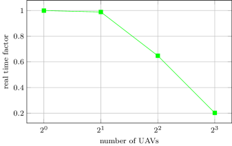
The results show that the RTF is always below one, meaning that the simulation never speeds up the experiments compared to real-world experiments. Furthermore, the performance significantly drops once the number of UAVs exceeds 2. This suggests that the detailed simulation requires one CPU core for each simulated CPS. If this condition is satisfied, the simulation runs nearly in real time.
We can compare the detailed and the abstract simulations through the total simulation time for all experiments. The abstract simulation takes about and to complete a total of 200 simulation runs. The detailed simulation takes about , and to complete a total of 246 simulation runs. The difference of several orders of magnitude shows the importance for the abstract simulation during the engineering process.
5.2 Performance Evaluation
The behavior of the swarm of CPSs that is designed using the process described in Section 3 is evaluated experimentally through simulations. As described in the previous section, we use two different types of simulations to measure the performance of the swarm behavior: first, an abstract simulation that provides results fast but less accurately. By observing the behavior of the simulated CPSs, it is possible to validate that the design process yields the desired results. The performance measures allow to determine whether the emerging swarm behavior meets the requirements. Second, a detailed simulation that provides more realistic results but requires more simulation time. The simulations provide results that allow measuring the performance of the emergent swarm behavior using well defined performance metrics. We qualitatively compare the outcomes of the two simulations in order to verify the outcomes of the design process. The abstract simulation evaluates the complete SAR behavior consisting of coverage, tracking, and reaching the target. The latter will be referred to as rescuing in the following. Because of the high implementation and simulation effort of the detailed simulation, only the coverage behavior is evaluated throughout this paper.
5.2.1 Coverage
Throughout this paper, we evaluate the coverage behavior using both, the abstract and the detailed simulation. It is implemented as a random direction algorithm where the UAVs fly on a straight line until they encounter an obstacle or the area boundary, and then randomly change their direction. While this algorithm is well suited for bounded environments, unbounded environments would require a different algorithm such as random walk (36).The results are then compared qualitatively to verify the outcomes of the design process. We evaluate the coverage efficiency by measuring the time it takes to cover a given percentage of the environment area. We chose the following percentages of interest
| (2) |
where the percentages are more and more fine grained the higher they get. Percentages below are not considered to be effective enough for the scenario. The environment in which the SAR takes place is a bounded, rectangular region without any obstacles. Unbounded environments would work just as well, however the performance metric would need to measure the covered area in absolute terms. All CPSs are placed in the center of the south side of the environment with equal spacing. Once the mission starts, all UAVs take off and start covering the area by departing in diverging directions chosen by dividing the available regularly by the number of UAVs. The simulation is performed with increasing swarm size using one, two, four, and eight UAVs.
5.2.2 Coverage
The abstract simulation
is implemented in Netlogo 6.1.1 (59; 60), an agent-based simulator using discrete time and space. The world is modeled as a square of patches. The UAVs are placed four patches apart and fly with a constant speed of one patch per tick. Their field of view (FOV) consists of the patch they are currently above plus the surrounding eight patches, i.e., the Moore neighborhood. The simulation is repeated 50 times per configuration. The results visualized in Figure 7a show the coverage efficiency, i.e., the average time for covering the different percentages of the environment, with error bars showing the confidence interval.
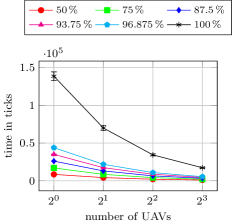
The coverage time is inversely proportional to the swarm size. It scales very well with increasing swarm size as doubling the number of UAVs approximately bisects the required coverage time. Increasing the coverage percentage linearly increases the coverage time exponentially. This is because the uncovered space decreases over time, increasing the redundancy of the coverage. This becomes evident for complete coverage (i.e. ) where the coverage time increases dramatically. This is because the random direction algorithm makes it very unlikely to choose exactly the right direction towards the last unexplored areas at the end of the exploration.
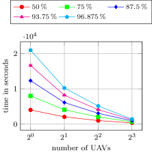
The detailed simulation
is based on ROS using the Gazebo simulator (26) which allows to perform high fidelity simulations based on a physics engine that simulates continuous space and time. As the simulations build on ROS the same behavior code generated for execution on the CPSs using the swarm and abstraction libraries can be used in simulation. This allows effective verification of the generated code using many simulation runs before the actual hardware deployment takes place. The random direction algorithm used for these simulations is released as ROS package111111https://wiki.ros.org/uav_random_direction. It is initialized with the UAVs being placed equally spaced with separation. The altitude of operation is above the ground giving the UAVs a FOV radius of approximately . They fly with an average speed of . The coverage is performed in an area of size . To get reliable results, the simulation is repeated multiple times for each parameter setting in order to reach a relative error of the data sample below with a confidence of . The results in terms of coverage efficiency can be seen in Figure 7b. The results are very similar to the ones from the abstract simulation. The coverage time is inversely proportional to the swarm size and increases exponentially with increasing coverage percentage. The absolute values are not directly comparable between the simulations as the difference in abstraction is too large. Nevertheless, if we assume that a simulated tick in abstract simulation takes about , there is a relative difference of approximately in coverage time between levels of abstraction. In the detailed simulation, it was unfeasible to reach coverage due to simulation time constraints. Therefore, results are shown only for a maximum value of . These results verify that the behavior obtained from the generated code meets the modeled behavior.
5.2.3 Search and Rescue
The abstract simulation for the SAR scenario consists of an extension of the coverage scenario simulation described above. We extended the simulation by adding targets to be rescued and UGVs performing the rescue. Targets are distributed uniform randomly in the world. A target is considered found when it comes into the FOV of a UAV; this is the search time for this target. The UAV then hovers over the site until a UGV reaches the target. To avoid UAVs from being blocked in tracking, there is one UGV exclusively assigned to each UAV. The UGV starts from the same initial location as the UAV that found the target and drives towards the target in a straight line with a constant speed of one patch per tick. As soon as the UGV reaches the target, this target is considered to be rescued and the UAV continues to search for further targets. We perform simulations to measure the rescue efficiency, i.e., the time until all targets are rescued. We perform the simulation with one, two, four, eight, 16, and 32 targets. Each configuration is simulated with 50 repetitions for statistical significance. Figure 8 shows the results of the abstract simulations for the SAR scenario.
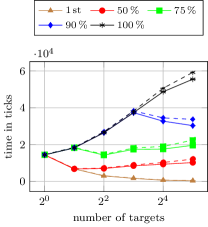
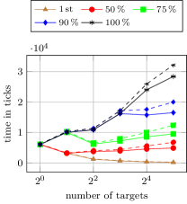
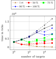
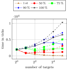
The figures show the average search times of targets (continuous lines) and the average rescue times of targets (dashed lines) for the first target, , , , and of the targets. As for the coverage simulation, the search times are inversely proportional to the number of UAVs. The rescue times are naturally larger than the search times since they include the traveling time of the UGVs. This traveling time stays constant, regardless of the number of employed UAVs. Therefore, with increasing number of UAVs and decreasing search time, the rescue time relative to the search time becomes larger. As expected, an increasing number of targets leads to increased search and rescue times. Exceptions only occur for low percentages of targets, e.g., finding one out of two targets is naturally faster than finding a single target. It should furthermore be noted that the target percentages are always rounded up since the number of targets is a discrete quantity. This leads to the effect where an increased number of targets decreases the search and rescue times. For example, looking at the line, one can observe finding two out of two targets is more costly than finding three out of four targets. These results confirm that the SAR mission performs as expected and hence validate the modeled behavior.
5.3 Proof of Concept
As a final step, real world experiments are performed to demonstrate that the engineering process generates code that can run on actual CPSs. For this purpose, we use an arena of size that contains three targets at random locations. The targets are implemented as AprilTags (58) being placed on the ground. The SAR is performed by three CPSs, one UAV that performs the coverage and tracking and two UGVs which perform the rescue. The UGVs are placed on one side of the environment whereas the UAV is placed at a random location inside the environment. This setup is shown in Figure 9.
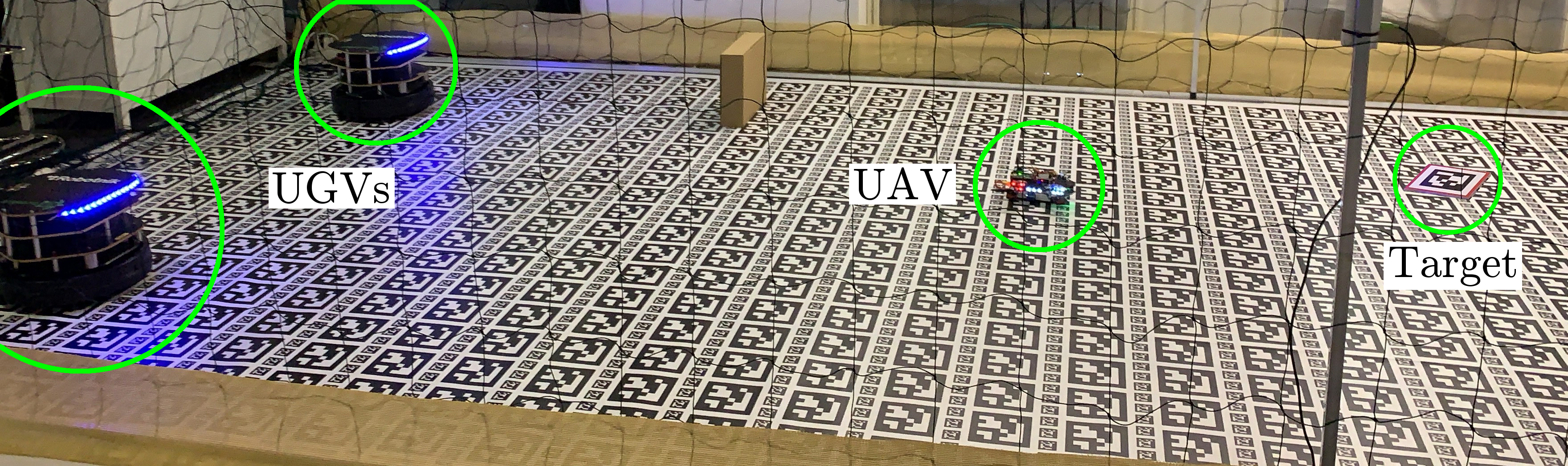
Several experiments are performed to demonstrate that the CPS behavior runs stable and performs as expected. An exemplary execution of the experiment can be seen on YouTube121212https://www.youtube.com/watch?v=p6mveXV4kv0. Figure 10 shows the timeline of the demonstration which is averaged over 21 runs.
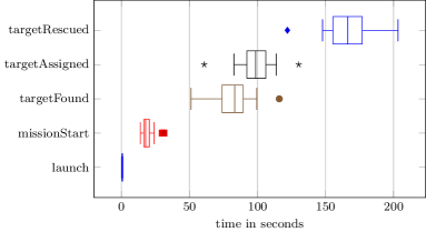
It shows box plots of the events happening during the mission execution. Each box is defined by the lower and upper quartiles and additionally visualizes the median, the lowest and highest datum still within 1.5 times the interquartile range (IQR) of the box as whiskers, and outliers and individual points. It can be seen that, despite some variations, the sequence of actions generated from the models can be successfully executed repeatedly on CPSs in real-world demonstrations. This final verification step attests the applicability of the engineering process.
6 Conclusion
This paper presents a toolchain for model-based engineering of CPS swarms and provides a proof-of-concept for a SAR scenario. We use a bottom-up design approach that yields the desired swarm behavior. We introduce a hierarchical model library that is based on the concepts of FSM from UML and SysML. These models are processed by an automatic code generator that generates a software bundle ready to be compiled, deployed, and interpreted on the target CPS.
We perform three validation and verification steps for the implementation of the CPS swarm in a SAR application. They serve as a proof-of-concept of the model-based engineering approach. First, we perform abstract simulations in Netlogo for rapid prototyping. Second, we perform detailed simulations in Gazebo that prove the correctness of the results. Third, we perform a physical deployment on a heterogeneous swarm of CPSs. The latter two use the generated code and run on ROS. A limitation of the presented implementation is the high demand for computing power by the detailed simulations. This limits the applicability to simple scenarios. We envision for future improvements to overcome this issue by integrating simulation software on cloud computing clusters.
The presented tools and libraries are part of the CPSwarm workbench131313https://www.cpswarm.eu/index.php/cpswarm-workbench/. It provides a central launcher that guides the user through the engineering steps. The CPSwarm workbench furthermore provides tools for bulk deployment (57), monitoring and control of the swarm, and an optimization environment that allows the generation of swarm member behaviors using evolutionary design (51). This workbench consists of individual tools using standardized interfaces. In the future we envision adding more tools to this workbench to provide alternatives for each step of the process. This would allow to satisfy the specific requirements of different applications. Currently, there are still some steps to be performed manually. The vision is to automate more and more steps of the engineering process. We encourage the reader to contribute tools to the workbench and enhance the modeling and behavior libraries. The currently available components are published online on GitHub and as ROS packages. They will be further developed and extended in the future. Our aim is to realize a standardized engineering approach for CPS swarm applications.
To conclude, we can say that the CPSwarm workbench effectively improves the development process of CPS swarms and produces efficient swarm algorithms. This paper presents the application to a SAR scenario, however the workbench can be applied to many other scenarios such as automotive CPSs (49) or swarm logistics (52).
References
- (1) Abbott, R.: Emergence explained: Abstractions: Getting epiphenomena to do real work. Complexity 12(1), 13–26 (2006). DOI 10.1002/cplx.20146
- (2) de Araujo, V., Almeida, A.P.G., Miranda, C.T., de Barros Vidal, F.: A parallel hierarchical finite state machine approach to uav control for search and rescue tasks. In: Proceedings of the International Conference on Informatics in Control, Automation and Robotics (ICINCO), pp. 410–415. IEEE (2014). DOI 10.5220/0005121104100415
- (3) Arnould, V., Balmelli, L., Bailey, I., Baker, J., Bialowas, C., Bock, C., Boettcher, C., Burkhart, R., Cantor, M., Douglass, B., Eisenmann, H., Ek, A., Ellis, B., Escue, M., Friedenthal, S., Gery, E., Hamilton, H., Hardy, D., Hummel, J., Kobryn, C., Latta, M., Low, J., Long, R., Marimuthu, K., Moore, A., Normand, V., Obeid, S., Palachi, E., Price, D., Selic, B., Sibbald, C., Skipper, J., Steiner, R., Thompson, R., U’Ren, J., Weilkiens, T., Weigert, T., , Willard, B.: Systems modeling language (SysML) version 1.5. Standard, Object Management Group (OMG) (2017). URL https://www.omg.org/spec/SysML/1.5
- (4) Bagnato, A., Bíró, R.K., Bonino, D., Pastrone, C., Elmenreich, W., Reiners, R., Schranz, M., Arnautovic, E.: Designing swarms of cyber-physical systems: The H2020 CPSwarm project: Invited paper. In: Proceedings of the Computing Frontiers Conference (CF), pp. 305–312. ACM (2017). DOI 10.1145/3075564.3077628
- (5) Bonabeau, E., Dorigo, M., Theraulaz, G.: Swarm intelligence: from natural to artificial systems. Oxford University Press, New York, NY, USA (1999)
- (6) Brambilla, M., Ferrante, E., Birattari, M., Dorigo, M.: Swarm robotics: a review from the swarm engineering perspective. Swarm Intelligence volume 7(1), 1–41 (2013). DOI 10.1007/s11721-012-0075-2
- (7) Brooks, R.: A robust layered control system for a mobile robot. IEEE Journal on Robotics and Automation 2(1), 14–23 (1986). DOI 10.1109/JRA.1986.1087032
- (8) Brosse, E., Quadri, I.R., Sadovykh, A., Ieromnimon, F., Kritharidis, D., Catrou, R., Sarlotte, M.: ENOSYS FP7 EU project: An integrated modeling and synthesis flow for embedded systems design. In: International Workshop on Reconfigurable and Communication-Centric Systems-on-Chip (ReCoSoC). IEEE (2012). DOI 10.1109/ReCoSoC.2012.6322880
- (9) Colledanchise, M., Ögren, P.: How behavior trees modularize hybrid control systems and generalize sequential behavior compositions, the subsumption architecture, and decision trees. IEEE Transactions on Robotics 33(2), 372–389 (2017). DOI 10.1109/TRO.2016.2633567
- (10) Cook, S., Bock, C., Rivett, P., Rutt, T., Seidewitz, E., Selic, B., Tolbert, D.: Unified modeling language (UML) version 2.5.1. Standard, Object Management Group (OMG) (2017). URL https://www.omg.org/spec/UML/2.5.1
- (11) Cornils, A., Hedin, G.: Tool support for design patterns based on reference attribute grammars. In: Proceedings of the Workshop on Attribute Grammars and their Applications (WAGA), pp. 21–38 (2000). URL https://pure.au.dk/portal/en/publications/id(82e63811-05ee-43f1-a8d9-5f8f20edf769).html
- (12) Do, T.T., Kolp, M., Pirotte, A.: Social patterns for designing multi-agent systems. In: Proceedings of the International Conference on Software Engineering and Knowledge Engineering (SEKE), pp. 103–110 (2003). URL https://hdl.handle.net/2078/18505
- (13) Eden, A.H., Yehudai, A., Gil, J.: Precise specification and automatic application of design patterns. In: Proceedings of the International Conference on Automated Software Engineering (ASE), pp. 143–152. IEEE (1997). DOI 10.1109/ASE.1997.632834
- (14) Faigl, J., Kulich, M.: On benchmarking of frontier-based multi-robot exploration strategies. In: Proceedings of the European Conference on Mobile Robots (ECMR). IEEE (2015). DOI 10.1109/ECMR.2015.7324183
- (15) Fernandez-Marquez, J.L., Di Marzo Serugendo, G., Montagna, S., Viroli, M., Arcos, J.L.: Description and composition of bio-inspired design patterns: a complete overview. Natural Computing 12(1), 43–67 (2013). DOI 10.1007/s11047-012-9324-y
- (16) Fitzgerald, J., Pierce, K., Larsen, P.G.: Co-modelling and co-simulation in the engineering of systems of cyber-physical systems. In: Proceedings of the International Conference on System of Systems Engineering (SOSE), pp. 67–72. IEEE (2014). DOI 10.1109/SYSOSE.2014.6892465
- (17) Francesca, G., Brambilla, M., Brutschy, A., Trianni, V., Birattari, M.: AutoMoDe: A novel approach to the automatic design of control software for robot swarms. Swarm Intelligence 8(2), 89–112 (2014). DOI 10.1007/s11721-014-0092-4
- (18) Friedenthal, S., Moore, A., Steiner, R.: A practical guide to SysML: the systems modeling language. Morgan Kaufmann, Waltham, MA, USA (2014)
- (19) Fritzson, P., Engelson, V.: Modelica — a unified object-oriented language for systems modeling. In: Proceedings of the European Conference on Object-Oriented Programming (ECOOP), pp. 67–90. Springer (2006). DOI 10.1007/BFb0054087
- (20) Gunes, V., Peter, S., Givargis, T., Vahid, F.: A survey on concepts, applications, and challenges in cyber-physical systems. KSII Transactions on Internet and Information Systems 8(12), 4242–4268 (2014). DOI 10.3837/tiis.2014.12.001
- (21) Hamann, H., Wörn, H.: A framework of space–time continuous models for algorithm design in swarm robotics. Swarm Intelligence 2(2-4), 209–239 (2008). DOI 10.1007/s11721-008-0015-3
- (22) Hassanien, A.E., Emary, E.: Swarm Intelligence: Principles, Advances, and Applications. CRC Press, Boca Raton, FL, USA (2015)
- (23) Henriksson, D., Elmqvist, H.: Cyber-physical systems modeling and simulation with modelica. In: Proceedings of the International Modelica Conference, pp. 502–509. Linköping University Electronic Press (2011). DOI 10.3384/ecp11063502
- (24) Jdeed, M., Schranz, M., Bagnato, A., Suleri, S., Prato, G., Conzon, D., Sende, M., Brosse, E., Pastrone, C., Elmenreich, W.: The cpswarm technology for designing swarms of cyber-physical systems. In: Proceedings of the Research Project Showcase Workshop (RPS), pp. 85–90. CEUR-WS (2019). URL https://hdl.handle.net/20.500.12004/1/C/STAF-RPS/2019
- (25) Kelly, S., Tolvanen, J.P.: Domain-Specific Modeling: Enabling Full Code Generation. John Wiley & Sons, Hoboken, NJ, USA (2008)
- (26) Koenig, N., Howard, A.: Design and use paradigms for Gazebo, an open-source multi-robot simulator. In: Proceedings of the International Conference on Intelligent Robots and Systems (IROS), pp. 2149–2154. IEEE/RSJ (2004). DOI 10.1109/IROS.2004.1389727
- (27) Kuckling, J., Ligot, A., Bozhinoski, D., Birattari, M.: Behavior trees as a control architecture in the automatic modular design of robot swarms. In: Proceedings of the International Conference on Swarm Intelligence (ANTS), pp. 30–43. Springer (2018). DOI 10.1007/978-3-030-00533-7˙3
- (28) Larsen, P.G., Fitzgerald, J., Woodcock, J., Fritzson, P., Brauer, J., Kleijn, C., Lecomte, T., Pfeil, M., Green, O., Basagiannis, S., Sadovykh, A.: Integrated tool chain for model-based design of cyber-physical systems: the INTO-CPS project. In: Proceedings of the International Workshop on Modelling, Analysis, and Control of Complex CPS (CPS Data). IEEE (2016). DOI 10.1109/CPSData.2016.7496424
- (29) Lee, E.A.: Cyber physical systems: Design challenges. In: Proceedings of the International Symposium on Object Oriented Real-Time Distributed Computing (ISORC), pp. 363–369. IEEE (2008). DOI 10.1109/ISORC.2008.25
- (30) Lee, E.A.: The past, present and future of cyber-physical systems: A focus on models. Transactions on Cyber-Physical Systems 1(1), 3:1–3:26 (2017). DOI 10.1145/2912149
- (31) Martin, P., Egerstedt, M.: Hybrid systems tools for compiling controllers for cyber-physical systems. Discrete Event Dynamic Systems 22(1), 101–119 (2012). DOI 10.1007/s10626-011-0117-8
- (32) Masin, M., Palumbo, F., Myrhaug, H., de Oliveira Filho, J.A., Pastena, M., Pelcat, M., Raffo, L., Regazzoni, F., Sanchez, A.A., Toffetti, A., de la Torre, E., Zedda, K.: Cross-layer design of reconfigurable cyber-physical systems. In: Proceedings of the Conference on Design, Automation & Test in Europe (DATE), pp. 740–745. European Design and Automation Association (2017). URL http://dl.acm.org/citation.cfm?id=3130379.3130559
- (33) McLurkin, J.D.: Stupid robot tricks: A behavior-based distributed algorithm library for programming swarms of robots. Ph.D. thesis, Massachusetts Institute of Technology (2004). URL http://hdl.handle.net/1721.1/28550
- (34) Murphy, R.R., Tadokoro, S., Nardi, D., Jacoff, A., Fiorini, P., Choset, H., Erkmen, A.M.: Search and rescue robotics. In: B. Siciliano, O. Khatib (eds.) Springer Handbook of Robotics, pp. 1151–1173. Springer Berlin Heidelberg, Berlin, Heidelberg (2008). DOI 10.1007/978-3-540-30301-5˙51
- (35) Parpinelli, R.S., Lopes, H.S.: New inspirations in swarm intelligence: a survey. International Journal of Bio-Inspired Computation 3(1), 1–16 (2011). DOI 10.1504/IJBIC.2011.038700
- (36) Pearson, K.: The problem of the random walk. Nature 72(1865), 294–294 (1905). DOI 10.1038/072294b0
- (37) Pinciroli, C., Trianni, V., O’Grady, R., Pini, G., Brutschy, A., Brambilla, M., Mathews, N., Ferrante, E., Caro, G.D., Ducatelle, F., Birattari, M., Gambardella, L.M., Dorigo, M.: ARGoS: a modular, parallel, multi-engine simulator for multi-robot systems. Swarm Intelligence 6(4), 271–295 (2012). DOI 10.1007/s11721-012-0072-5
- (38) Pitonakova, L., Crowder, R., Bullock, S.: Behaviour-data relations modelling language for multi-robot control algorithms. In: Proceedings of the International Conference on Intelligent Robots and Systems (IROS), pp. 727–732. IEEE/RSJ (2017). DOI 10.1109/IROS.2017.8202231
- (39) Quadri, I., Bagnato, A., Brosse, E., Sadovykh, A.: Modeling methodologies for cyber-physical systems: Research field study on inherent and future challenges. Ada User Journal 36(4), 246–253 (2015). URL http://www.ada-europe.org/archive/auj/auj-36-4.pdf
- (40) Quigley, M., Gerkey, B., Conley, K., Faust, J., Foote, T., Leibs, J., Berger, E., Wheeler, R., Ng, A.: ROS: an open-source robot operating system. In: Proceedings of the ICRA Workshop on Open Source Software in Robotics (2009). URL http://www.willowgarage.com/sites/default/files/icraoss09-ROS.pdf
- (41) Rabbath, C.A.: A finite-state machine for collaborative airlift with a formation of unmanned air vehicles. Journal of Intelligent & Robotic Systems 70(1-4), 233–253 (2013). DOI 10.1007/s10846-012-9692-7
- (42) Rand, W., Wilensky, U.: Full spectrum modeling: From simplicity to elaboration and realism in urban pattern formation. In: Proceedings of the North American Association of Computational Social and Organization Sciences Conference (NAACSOS) (2007). URL http://ccl.northwestern.edu/2007/FullSpectrum-naacsos.pdf
- (43) Reimann, M., Ruckriegel, C., Mortimer, S., Bageritz, S., Henshaw, M., Siemieniuch, C., Sinclair, M.A., Palmer, P.J., Fitzgerald, J., Ingram, C., Servat, D., Stock, D., Rauschecker, U., Gotz, B., Ordonez, D., Butler, T., de Lama, N., Rico, J., Alonso, J.: Road2CPS priorities and recommendations for research and innovation in cyber-physical systems. Steinbeis-Edition, Stuttgart, Germany (2017)
- (44) Rickert, M., Gaschler, A.: Robotics Library: An object-oriented approach to robot applications. In: Proceedings of the International Conference on Intelligent Robots and Systems (IROS), pp. 733–740. IEEE/RSJ (2017). DOI 10.1109/IROS.2017.8202232
- (45) Roy, P., Tabuada, P., Majumdar, R.: Pessoa 2.0: a controller synthesis tool for cyber-physical systems. In: Proceedings of the International Conference on Hybrid Systems: Computation and Control (HSCC), pp. 315–316. ACM (2011). DOI 10.1145/1967701.1967748
- (46) Şahin, E.: Swarm robotics: From sources of inspiration to domains of application. In: Proceedings of the International Workshop on Swarm Robotics (SR), pp. 10–20. Springer (2004). DOI 10.1007/978-3-540-30552-1˙2
- (47) Schranz, M., Bagnato, A., Brosse, E., Elemenreich, W.: Modelling a cps swarm system: A simple case study. In: Proceedings of the International Conference on Model-Driven Engineering and Software Development (MODELSWARD), pp. 615–624. SciTePress (2018). DOI 10.5220/0006731106150624
- (48) Schranz, M., Sende, M., Bagnato, A., Brosse, E.: Modeling swarm intelligence algorithms for cps swarms. Ada User Journal 40(3), 169–177 (2019). URL https://www.ada-europe.org/archive/auj/auj-40-3.pdf
- (49) Schranz, M., Sende, M., Bagnato, A., Brosse, E., Eckel, A.: Modeling cps swarms: An automotive use case. Ada User Journal 40(3), 165–168 (2019). URL https://www.ada-europe.org/archive/auj/auj-40-3.pdf
- (50) Schranz, M., Umlauft, M., Sende, M., Elmenreich, W.: Swarm robotic behaviors and current applications. Frontiers in Robotics and AI 7(36) (2020). DOI 10.3389/frobt.2020.00036
- (51) Sende, M., Conzon, D., Pitman, A., Schranz, M., Ferrera, E., Jdeed, M., Pastrone, C., Elmenreich, W.: Scalable distributed simulation for evolutionary optimization of swarms of cyber-physical systems. International Journal On Advances in Systems and Measurements 12(1&2), 135–147 (2019)
- (52) Soriano, A.: D8.4 – final swarm logistics demonstration. Public deliverable, EU H2020 CPSwarm Consortium (2017). URL https://www.cpswarm.eu/wp-content/uploads/2020/06/D8.4-FINAL-SWARM-LOGISTICS-DEMONSTRATION_v1.0-FINAL.pdf
- (53) Soysal, O., Sahin, E.: Probabilistic aggregation strategies in swarm robotic systems. In: Proceedings of the Swarm Intelligence Symposium (SIS), pp. 325–332. IEEE (2005). DOI 10.1109/SIS.2005.1501639
- (54) Spears, W.M., Gordon, D.F.: Evolving finite-state machine strategies for protecting resources. In: Proceedings of the International Symposium on Methodologies for Intelligent Systems (ISMIS), pp. 166–175. Springer (2000). DOI 10.1007/3-540-39963-1˙18
- (55) Sztipanovits, J., Bapty, T., Neema, S., Howard, L., Jackson, E.: OpenMETA: A model- and component-based design tool chain for cyber-physical systems. In: Proceedings of the ETAPS Workshop, From Programs to Systems - The Systems perspective in Computing (FPS), pp. 235–248. Springer (2014). DOI 10.1007/978-3-642-54848-2˙16
- (56) Sztipanovits, J., Ying, S., Cohen, I., Corman, D., Davis, J., Khurana, H., Mosterman, P.J., Prasad, V., Stormo, L.: Strategic R&D opportunities for 21st century cyber-physical systems: Connecting computer and information systems with the physical world. Tech. rep., National Institute of Standards and Technology (NIST) (2013). URL https://www.nist.gov/el/cyber-physical-systems/cyber-physical-systems
- (57) Tavakolizadeh, F., Chala, S.A., Zhang, H.: An interactive interface for bulk software deployment in IoT. In: Proceedings of the International Conference on the Internet of Things (IoT). ACM (2019). DOI 10.1145/3365871.3365912
- (58) Wang, J., Olson, E.: AprilTag 2: Efficient and robust fiducial detection. In: Proceedings of the International Conference on Intelligent Robots and Systems (IROS), pp. 4193–4198. IEEE/RSJ (2016). DOI 10.1109/IROS.2016.7759617
- (59) Wilensky, U.: Netlogo. http://ccl.northwestern.edu/netlogo/. Center for Connected Learning and Computer-Based Modeling, Northwestern University, Evanston, IL.
- (60) Wilensky, U., Rand, B.: Introduction to Agent-Based Modeling: Modeling Natural, Social and Engineered Complex Systems with NetLogo. The MIT Press, Cambridge, MA, USA (2015)
- (61) Yang, X.S., Deb, S., Zhao, Y.X., Fong, S., He, X.: Swarm intelligence: past, present and future. Soft Computing 22(18), 5923–5933 (2018). DOI 10.1007/s00500-017-2810-5