Unidirectional magnetoresistance and spin-orbit torque in NiMnSb
Abstract
Spin-dependent transport phenomena due to relativistic spin-orbit coupling and broken space-inversion symmetry are often difficult to interpret microscopically, in particular when occurring at surfaces or interfaces. Here we present a theoretical and experimental study of spin-orbit torque and unidirectional magnetoresistance in a model room-temperature ferromagnet NiMnSb with inversion asymmetry in the bulk of this half-heusler crystal. Besides the angular dependence on magnetization, the competition of Rashba and Dresselhaus-like spin-orbit couplings results in the dependence of these effects on the crystal direction of the applied electric field. The phenomenology that we observe highlights potential inapplicability of commonly considered approaches for interpreting experiments. We point out that, in general, there is no direct link between the current-induced non-equilibrium spin polarization inferred from the measured spin-orbit torque and the unidirectional magnetiresistance. We also emphasize that the unidirectional magnetoresistance has not only longitudinal but also transverse components in the electric field – current indices which complicates its separation from the thermoelectric contributions to the detected signals in common experimental techniques. We use the theoretical results to analyze our measurements of the on-resonance and off-resonance mixing signals in microbar devices fabricated from an epitaxial NiMnSb film along different crystal directions. Based on the analysis we extract an experimental estimate of the unidirectional magnetoresistance in NiMnSb.
I Introduction
Anisotropic magnetoresistance (AMR) is an example of a relativistic transport phenomenon in ferromagnets with a long history. McGuire and PotterMcguire and Potter (1975) provided a phenomenological model that fully explained the angular dependence of AMR. The model was based on a general argument that the magnetisation dependent conductivity tensor , like any other observable,Neumann (1885) reflects the symmetry of the ferromagnetic crystal. This means that if a symmetry operation belongs to the crystallographic point group, the conductivity tensor is left invariant under the same symmetry operation. As an example, when an electrical current flows in an isotropic (polycrystalline) ferromagnet, the magnetisation direction defines the only axis of rotational symmetry, which results in a angular dependence of AMR, with being the angle between the magnetisation and the current.
While AMR can be observed in any magnetic system, ferromagnetic conductors with an inversion asymmetric crystal structure have been more recently identified as a fruitful platform for discovering and utilizing a range of new relativistic spintronics phenomena.Bernevig and Zhang (2005); Chernyshov et al. (2009); Fang et al. (2011); Kurebayashi et al. (2014); Ciccarelli et al. (2015, 2016) Apart from the exchange field , which splits the electronic structure in majority and minority spin bands, the inversion symmetry breaking in the lattice together with spin-orbit coupling introduces an additional splitting . Here is an effective magnetic field that depends on the crystal momentum , while represents the spin-polarisation. The key property of is that it is odd in and thus it results in opposite spin splitting for opposite . In inversion asymmetric strained zinc-blende semiconductors like GaAs, is a combination of Rashba and Dresselhaus symmetry terms, and . A direct manifestation of this splitting is found in the spin-orbit torque (SOT) Manchon et al. (2019) in, e.g., (Ga,Mn)As that emerge when an electrical current is applied to this inversion-asymmetric ferromagnetic semiconductor.Bernevig and Zhang (2005); Chernyshov et al. (2009); Fang et al. (2011); Kurebayashi et al. (2014) In metallic systems such as half-heusler NiMnSb studied here, is not described by the simple linear-in- Rashba and Dresselhaus form. SOT, nevertheless, contains Rashba and Dreselhaus-like terms analogous to those observed in the zinc-blende semiconductors as those reflect the crystal symmetry which is the same in zinc-blende and half-heusler crystals.Ciccarelli et al. (2016)
SOT in bulk non-centrosymmetric crystals is associated with a current-induced non-equilibrium spin polarisation , an effect often referred to as the Edelstein effect or the inverse spin-galvanic effect (iSGE).Silov et al. (2004); Kato et al. (2004); Ganichev et al. (2004); Wunderlich et al. (2005); Sinova et al. (2015); Manchon et al. (2019) When is perpendicular to the magnetization, it will exert a torque on it via the exchange coupling. The component of that is parallel to does not lead to a magnetization torque and is, therefore, transparent to any experimental method that relies on driving the magnetisation out of equilibrium by SOT.Fang et al. (2011); Garello et al. (2013); Manchon et al. (2019)
Besides SOT, together with can also lead to magneto-transport terms that are second order in the applied electric field and, unlike the first-order AMR, are odd under the magnetization. The unidirectional magnetoresistance (UMR) is an example of such a second-order magneto-transport effect that was previously reported in non-centrosymmetric ferromagnet/paramagnet bilayers or bulk ferromagnets.Avci et al. (2015); Olejník et al. (2015) The origin of UMR was considered to be closely connected to the phenomenology of the giant magnetoresistance (GMR).Baibich et al. (1988); Binasch et al. (1989); Olejník et al. (2015); Avci et al. (2018) While in the GMR multilayer, the fixed reference ferromagnetic layer acts as an external source of spin , in UMR this is replaced with generated internally by the spin-orbit coupling. As for GMR, spin-dependent scattering within the ferromagnet results in this scenario in a different resistance depending on the orientation of relative to the magnetization of the probed ferromagnet. Moreover, the accumulated spin can introduce a proportional change in the exchange splitting of the bands, further affecting the conductivity by influencing spin transmission of minority and majority spins. Another UMR mechanism considers that the magnons’ population of the ferromagnet is increased or decreased depending on the orientation of relative to the magnetisation. This leads to a change in the average magnetisation, which also results in a net change of the magnetoresistance. Although it is possible to experimentally distinguish these different contributions for their particular dependence on current density and magnetic field,Avci et al. (2018); Langenfeld et al. (2016) they all share a common origin in the component of collinear with the ferromagnet’s magnetisation.
In Sec. II we report our symmetry analysis and ab initio calculations of current induced spin polarization and UMR in NiMnSb. We use this model system to highlight potential misconceptions when inferring these quantities from experiment. In Sec. III we then discuss our measurements in NiMnSb microbars patterned along different crystal directions, and in Sec. IV we summarize our main results.
II Theoretical results and general implications for the analysis of experiments
II.1 Current-induced spin polarization and spin-orbit torque
The tetragonal distortion of the non-centrosymmetric cubic unit cell of NiMnSb, induced by the lattice mismatch with the substrate, lowers its symmetry to a symmetry point group and results in a Dresselhaus-like -linear term of the spin-orbit coupling. Experiments in NiMnSb epilayers show an additional Rashba-like -linear term of the spin-orbit coupling which we model by introducing a shear strain.Ciccarelli et al. (2016) This lowers the symmetry further to a point group . When an electrical current is passed in the plane perpendicular to the growth direction, carriers acquire a non-equilibrium spin polarization , which in general can be decomposed into a component that is parallel to the in-plane magnetisation of the NiMnSb film, , and a component that is perpendicular to it, . This includes both intrinsic and extrinsic contributions.
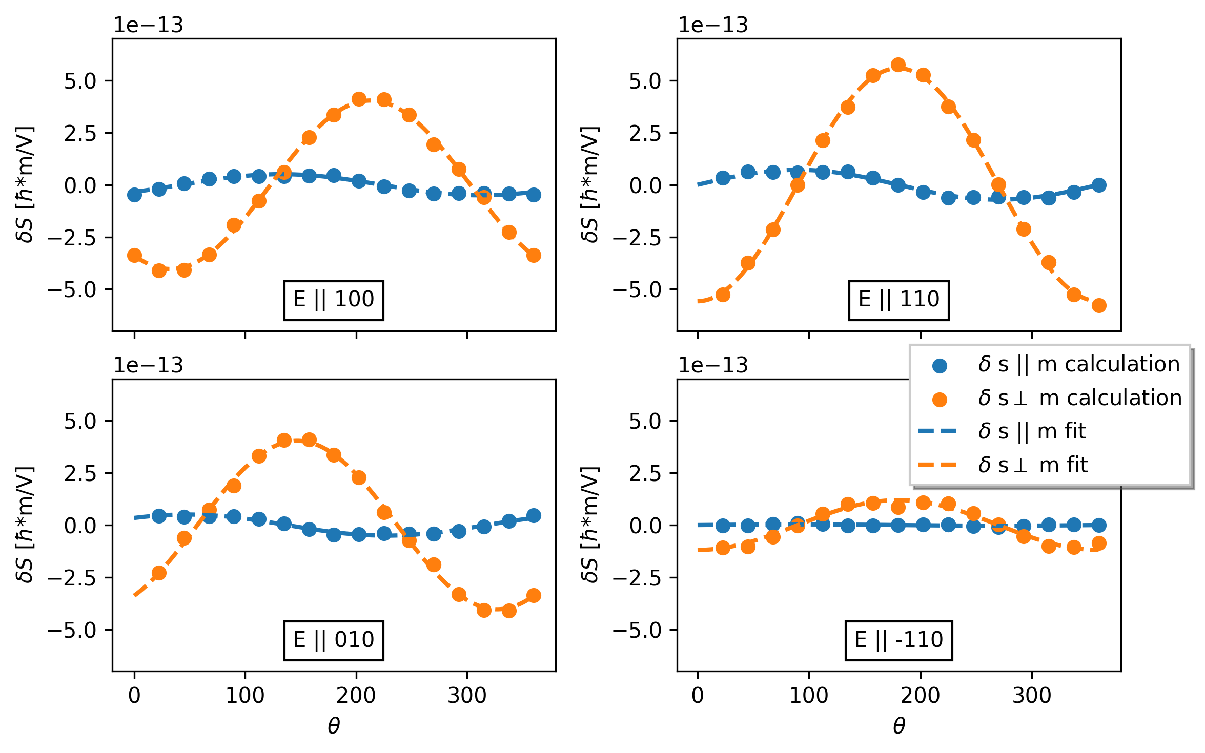
We use ab-initio calculations to evaluate the current-induced non-equilibrium spin polarization as a function of the directions of magnetization and applied electric field (see Appendix C for the description of the numerical method). We consider here only the in-plane components of current-induced spin-polarization since this is the component relevant for the UMR and the field-like torque. For these calculations we used the relaxation time chosen so that the theoretical conductivity matches the experimental value of Scm-1. The tetragonal and shear strains are chosen to make the Rashba and Dresselhaus contributions of comparable strength,Ciccarelli et al. (2016) resulting in a non-trivial dependence of on the crystal direction of the applied electric field. In Fig. 1 we plot the perpendicular () and parallel () components of the current-induced non-equilibrium spin polarization. The dependence of on the magnetization angle corresponds to what we would expect to find for a field-like SOT generated by a magnetisation-independent effective spin-orbit field, , where is the exchange constant between carrier spins and the in-plane magnetisation m. would then correspond to the angle of for the given crystal direction of the applied electric field. In our case, for the electric field along or axes since the Rashba and Dresselhaus-like spin-orbit fields are (anti)parallel for these two crystal directions. For or axes, the two spin-orbit fields are orthogonal to each other and their vector sum results in .
Remarkably, when we include , total becomes magnetization-dependent (see Figs. 1). We emphasize that this dependence of () on the magnetization angle would be invisible when measuring SOT, which only depends on . SOT can be reliably obtained from on-resonance mixing-signal measurements since the detected signal can be directly attributed to the precessing magnetization driven by the SOT. Our calculations in Fig. 1 demonstrate, however, that a simple harmonic dependence of on the magnetization angle, when inferred from the SOT measurement, does not imply that the total is constant and that its parallel component is a 90∘-phase shifted replica of the perpendicular component. Therefore, if considering as the driving mechanism behind UMR, SOT measurements cannot be, in general, used to quantify experimentally in a given structure.
II.2 Unidirectional magnetoresistance
When writing the total current density up to the second order in the applied electric filed as,
| (1) |
UMR has been associated with the longitudinal component of the transport coefficient.Avci et al. (2015); Olejník et al. (2015) Formally, is described by the second order quantum mechanical Kubo formula. However, finding accurate solutions of the formula is a major challenge, in particular in the presence of electron scattering. Here we analyze using a semiclassical Boltzmann approximation, where
| (2) |
and , is the Fermi-Dirac equilibrium distribution function, and is the band energy (see Appendix A for the derivation of this formula).
Since the group velocity is odd under space inversion, the second-order term will vanish in crystals that have inversion symmetry. Moreover, it will also vanish in nonmagnetic crystals since is odd under time-reversal. Furthermore, similarly to the anomalous Hall effect in coplanar magnetic systems, the second-order term will vanish in the absence of spin-orbit coupling, as the system will then be invariant under combined spin rotation and time-reversal symmetry.Zhang et al. (2018) will thus be present in magnetic crystals with broken inversion symmetry as a consequence of the spin-orbit coupling. These are the same symmetry requirements as for the existence of SOT.
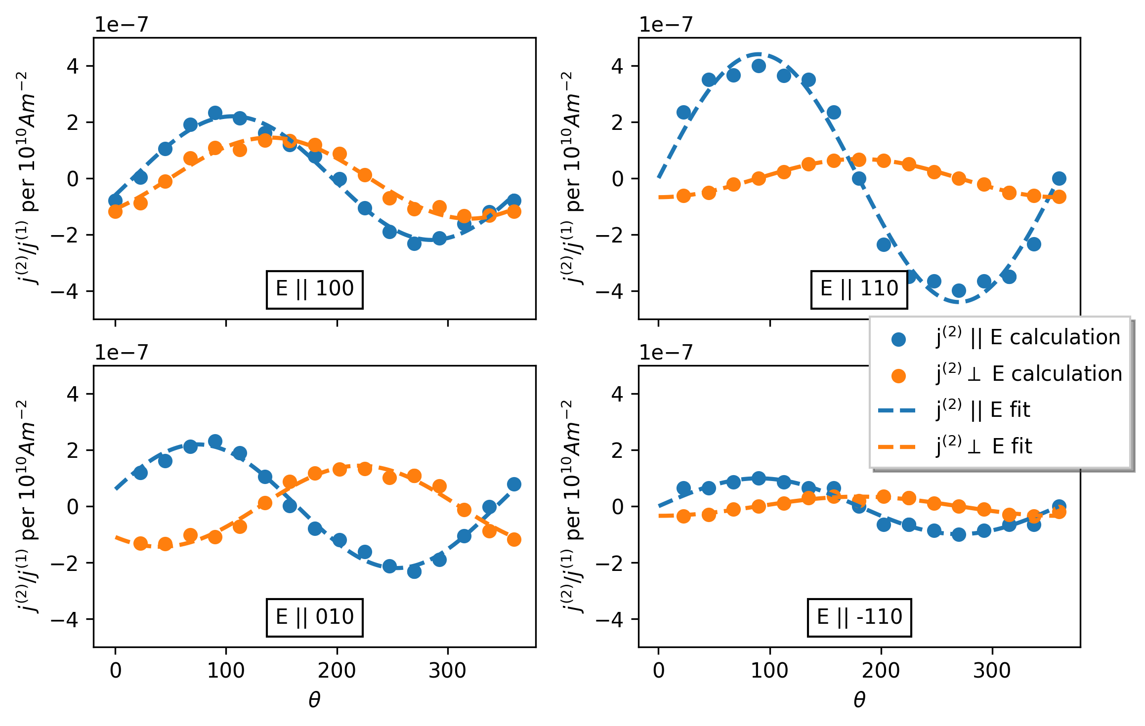
In Fig. 2 we plot the calculations of the longitudinal and transverse components of the second-order current obtained from the Boltzmann equation (2), normalized to the first-order current as a function of the magnetization angle for different directions of the electric field and for a current density of Am-2. The relative amplitudes of the longitudinal component for different directions of the applied electric field are similar to the relative amplitudes of (cf. Figs. 1 and 2). In both cases, the amplitudes are comparable for the electric field along and axes, while the largest/smallest amplitude is obtained for fields along axes. From these results we can expect similar amplitude ratios also in the measured UMR and SOT. We point out, however, that this is not necessarily a consequence of a common proportionality of UMR and SOT to . The Boltzmann approximation formula (2) gives an explicit example of a contribution to UMR with no direct relationship to . The similar amplitude ratios in the two cases are merely a reflection of a common Rashba-Dresselhaus-like symmetry of the underlying spin-orbit coupled electronic structure.
Our calculations in Fig. 2 also illustrate that the second-order current can have a sizable transverse component. Specifically in NiMnSb, the transverse component has a comparable amplitude to the longitudinal component for and crystal directions. Here we recall that in earlier experimental studies, the separation of UMR from competing thermo-electric contributions was based on the assumption that UMR had only a longitudinal component while the thermal effects contributed to both longitudinal and transverse signals.Avci et al. (2015); Olejník et al. (2015) Our results show that using the transverse signal for experimentally calibrating the magnitude of the thermal contribution is not, in general, reliable because the transverse component can also contain a contribution from UMR.
III Measured data and discussion
In our experiments, we pattern all our bard from the same 34 nm thick film of ferromagnetic NiMnSb epitaxially grown on a 200 nm thick In0.53Ga0.47As buffer layer on an Fe:InP insulating substrate and capped with a 5 nm MgO layer. The vertical lattice constant of 5.97 Å indicates that the film is under compressive strain and is close to a stoichiometric composition.Gerhard et al. (2014) Fig. 3a illustrates our measurement set-up. The NiMnSb film is patterned into m2 bars along different crystal directions and mounted on the rotational stage of an electromagnet. A microwave current is passed in the bars and the polarizing action of the spin-orbit coupling induces an oscillating non-equilibrium spin population which scales linearly with the current. The transverse component is responsible for generating torques on the magnetisation via the effective field . As described in the previous paragraph, the longitudinal component is responsible for generating both longitudinal and transverse components of the unidirectional magnetoresistance. Here we focus on the longitudinal components only and measure the dc longitudinal voltage via a bias tee.
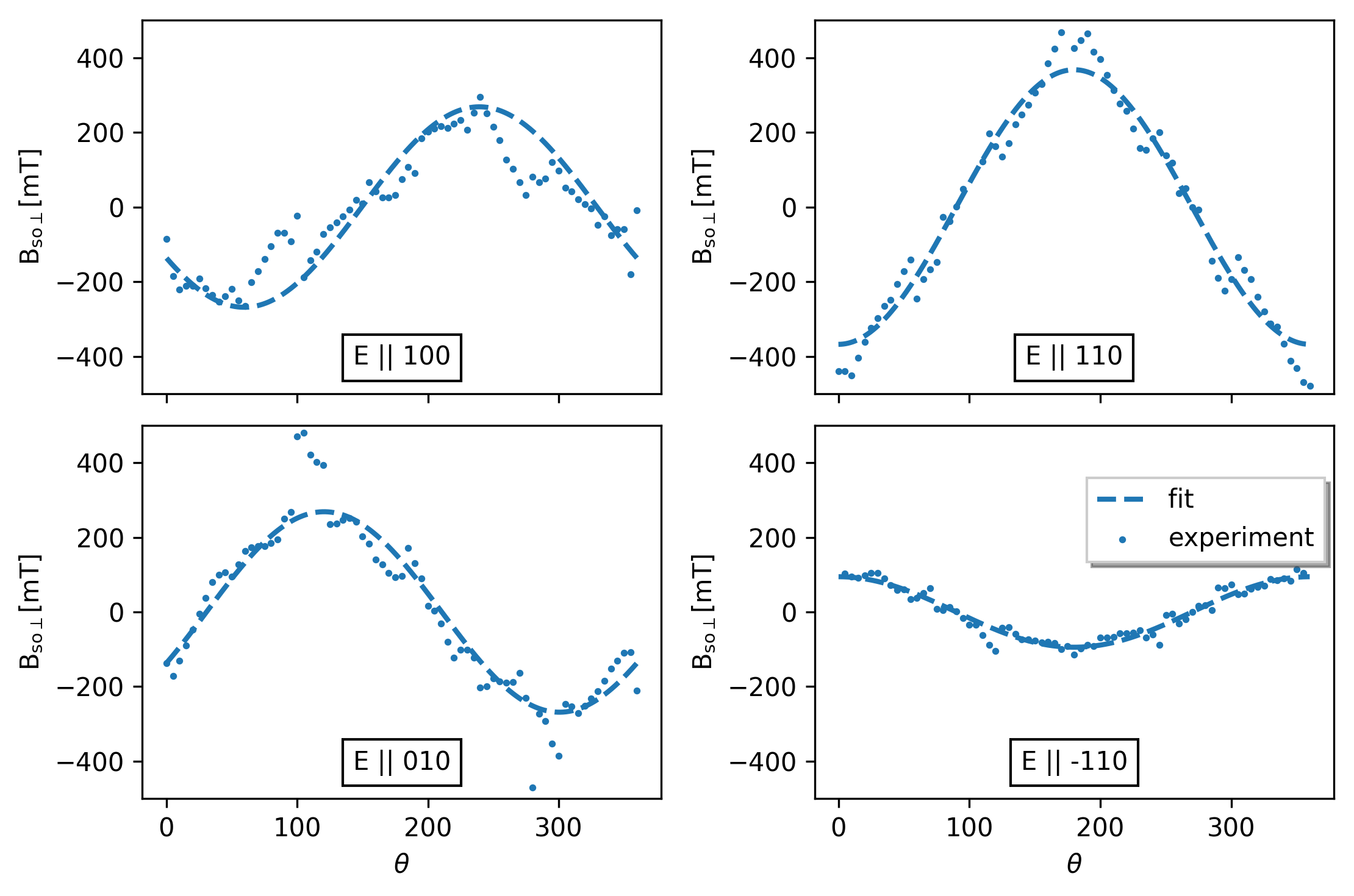
When ferromagnetic resonance is excited, rectification between the microwave current and the oscillating AMR results in a resonance in .Fang et al. (2011) The resonance is clearly visible in the 2D plots in Fig. 3b. It shows as a function of the external magnetic field and its direction with respect to the current direction, for bars parallel to the [10] and [100] axes. From the analysis of its line-shape (see Ref. Kurebayashi et al., 2014 for details) we are able to quantify . In agreement with previous studies on different systems,Fang et al. (2011); Kurebayashi et al. (2014); Garello et al. (2013) we experimentally identify the -dependence of for the different crystal directions in which the microbars are patterned, as shown in Fig. 4. As in the theoretical calculations of , the amplitudes of measured for bars along the [100] and [010] axes are similar, while the largest/smallest amplitudes are obtained for the directions, consistent with the combined Rashba-Dresselhaus-like symmetry of the NiMnSb electronic struture. The theoretical magnitude of T at Am-2 current density was reported earlier in Ref. Ciccarelli et al., 2016 and is of the same order of magnitude as in the experiment.
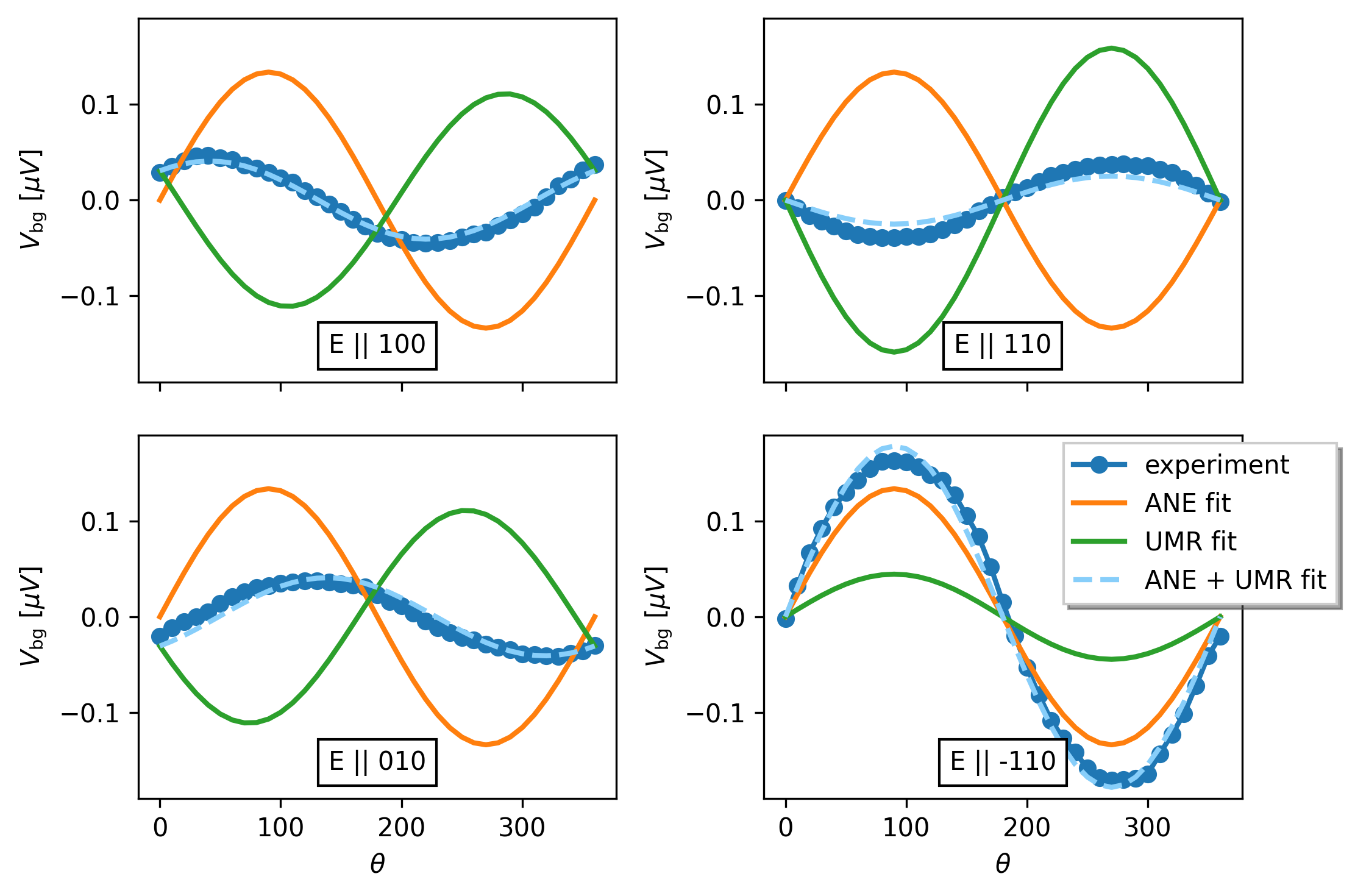
In Fig. 3b we notice that the resonance is sitting on a sinusoidally varying background, which we refer to as . This is also shown in Fig. 5, where the -dependence of the background voltage at a saturating magnetic field is plotted for bars patterned along the four different crystal directions [100], [010], [110] and [10]. The striking feature is that the magnitude of is again strongly dependent on the bar direction, however, the directions corresponding to the largest and smallest switched place compared to (or ). We note that these amplitude ratios of , as well as the crystal direction dependent phase shifts, are reproducible in different physical sets of samples patterned along the four crystal directions and do not depend on applied power, as shown in Appendix D.
To interpret the measured we now consider UMR and the thermoelectric contribution, namely the anomalous Nernst effect (ANE). When exciting the system by the applied ac current, an out-of-plane temperature gradient due to Joule heating can result in an electrical signal detected in the sample plane due to ANE. Since the heat deposited by the current scales with the square of the current density, ANE is a second-order effect in the electric field, just like the second order term of the conductivity. Based on a recent experimental measurementSharma et al. (2019) of ANE in NiMnSb and our numerical simulation of the heat gradient, we estimate that the contribution to due to ANE is V per current density of Am-2 (see Appendix E). While the magnitude is similar to that of the measured signals in Fig.5, we do not expect a strong dependence of the ANE contribution to on the crystal direction of the applied current. This is because ANE requires only the time-reversal symmetry breaking by the magnetization while broken spatial symmetries of the crystal only lead to additional, higher order corrections.
UMR, on the other hand, is generated by the inversion symmetry breaking which is of the combined Rashba-Dresselhaus-like form in our NiMnSb samples. As discussed in the theory section, this leads to a strong crystal direction dependence of the UMR. Since theory suggests that the amplitude ratios for the different crystal directions of SOT and UMR are similar, we can use this as a constraint when fitting the measured data. The results of the fitting shown in Fig. 5 were obtained by assuming fixed amplitude ratios of UMR, corresponding to the measured amplitude ratios of the SOT fields , plus an ANE contribution with an amplitude which is independent of the crystal direction. The extracted experimental ANE component is of the same order of magnitude as the above estimate. The fitted UMR contribution is an order of magnitude larger than our theoretical value which we attribute to the crude semiclassical Boltzmann approximation used in the UMR calculations. In the future, more elaborate Kubo formula calculations seem necessary to capture UMR in NiMnSb on the quantitative level. They will also allow for verifying the correspondence between the SOT and UMR amplitude ratios, and by this for more firmly establishing the fitting method we used to separate the UMR and thermoelectric contributions in the measured data.
IV Summary
Based on our study of ferromagnetic NiMnSb with non-centrosymmetric bulk crystal structure we make the following observations regarding the explored non-equilibrium spin-orbit coupling effects: (i) A harmonic dependence on the magnetization angle of the component of the current-induced spin polarization transverse to the magnetization does not imply, in general, that the in-plane component is its 90∘ phase shifted replica with the same amplitude. Despite the harmonic dependence of the transverse component, the total spin polarization vector, and the corresponding total current-induced spin-orbit field vector, is not necessarily independent of the magnetization angle. As a result, a measurement of SOT, driven by the transverse component of the current-induced spin-orbit field, should not be used, in general, for extracting the total non-equilibrium spin-orbit field (spin polarization) vector. (ii) The approximate Boltzmann theory of UMR, together with the approximate assumption of SOT being proportional to the current-induced spin polarization, suggest that the amplitude ratios of UMR and SOT for electric fields applied along different crystal directions are similar. This can be used for separating experimental UMR and thermoelectric (e.g. ANE) contributions, by employing independently measured SOT. On the other hand, measurements of the diagonal and off-diagonal components in the electric field – current indices is not, in general, a reliable tool for separating UMR and thermoelectric contributions because both can have sizable diagonal and off-diagonal components. (iii) Finally, the Boltzmann theory also illustrates that UMR can have microscopic contributions which are not directly related to the current-induced spin polarization vector. Similar phenomenologies observed in UMR and SOT can be a mere reflection of the common underlying relativistic electronic structure with broken time and space inversion symmetries.
Acknowledgements.
We acknowledge the Grant Agency of the Czech Republic Grant No. 19-18623Y, Ministry of Education of the Czech Republic Grants LM2018110, LNSM-LNSpin and e-Infrastructure CZ – LM2018140, EU FET Open RIA Grant No. 766566 and support from the Institute of Physics of the Czech Academy of Sciences and the Max Planck Society through the Max Planck Partner Group Programme. CC acknowledges support from the Royal Society. JPP acknowledges support from the EPSRC. The work of JZ was supported by the Ministry of Education, Youth and Sports of the Czech Republic from the OP RDE programme under the project International Mobility of Researchers MSCA-IF at CTU No. CZ.02.2.69/0.0/0.0/18_070/0010457.References
- Mcguire and Potter (1975) T. R. Mcguire and R. I. Potter, IEEE Transactions on Magnetics 11, 1018 (1975).
- Neumann (1885) F. E. Neumann, in Leipzig, B. G. Teubner-Verlag, edited by O. E. Meyer (1885).
- Bernevig and Zhang (2005) B. A. Bernevig and S. C. Zhang, Physical Review B 72, 115204 (2005).
- Chernyshov et al. (2009) A. Chernyshov, M. Overby, X. Liu, J. K. Furdyna, Y. Lyanda-Geller, and L. P. Rokhinson, Nature Physics 5, 656 (2009).
- Fang et al. (2011) D. Fang, H. Kurebayashi, J. Wunderlich, K. Výborný, L. P. Zârbo, R. P. Campion, A. Casiraghi, B. L. Gallagher, T. Jungwirth, and A. J. Ferguson, Nature Nanotechnology 6, 413 (2011).
- Kurebayashi et al. (2014) H. Kurebayashi, J. Sinova, D. Fang, A. C. Irvine, T. D. Skinner, J. Wunderlich, V. Novák, R. P. Campion, B. L. Gallagher, E. K. Vehstedt, L. P. Zârbo, K. Výborný, A. J. Ferguson, and T. Jungwirth, Nature Nanotechnology 9, 211 (2014), arXiv:1306.1893 .
- Ciccarelli et al. (2015) C. Ciccarelli, K. M. Hals, A. Irvine, V. Novak, Y. Tserkovnyak, H. Kurebayashi, A. Brataas, and A. Ferguson, Nature Nanotechnology 10, 50 (2015).
- Ciccarelli et al. (2016) C. Ciccarelli, L. Anderson, V. Tshitoyan, A. J. Ferguson, F. Gerhard, C. Gould, L. W. Molenkamp, J. Gayles, J. Železný, L. Šmejkal, Z. Yuan, J. Sinova, F. Freimuth, and T. Jungwirth, Nature Physics 12, 855 (2016).
- Manchon et al. (2019) A. Manchon, J. Železný, I. M. Miron, T. Jungwirth, J. Sinova, A. Thiaville, K. Garello, and P. Gambardella, Reviews of Modern Physics 91, 035004 (2019).
- Silov et al. (2004) A. Y. Silov, P. A. Blajnov, J. H. Wolter, R. Hey, K. H. Ploog, and N. S. Averkiev, Applied Physics Letters 85, 5929 (2004).
- Kato et al. (2004) Y. K. Kato, R. C. Myers, A. C. Gossard, and D. D. Awschalom, Physical Review Letters 93, 176601 (2004).
- Ganichev et al. (2004) S. D. Ganichev, S. N. Danilov, P. Schneider, V. V. Bel’kov, L. E. Golub, W. Wegscheider, D. Weiss, and W. Prettl, (2004), arXiv:0403641 .
- Wunderlich et al. (2005) J. Wunderlich, B. Kaestner, J. Sinova, and T. Jungwirth, Physical Review Letters 94, 047204 (2005), arXiv:0410295 [cond-mat] .
- Sinova et al. (2015) J. Sinova, S. O. Valenzuela, J. Wunderlich, C. H. Back, and T. Jungwirth, Reviews of Modern Physics 87, 1213 (2015).
- Garello et al. (2013) K. Garello, I. M. Miron, C. O. Avci, F. Freimuth, Y. Mokrousov, S. Blügel, S. Auffret, O. Boulle, G. Gaudin, and P. Gambardella, Nature Nanotechnology 8, 587 (2013).
- Avci et al. (2015) C. O. Avci, K. Garello, A. Ghosh, M. Gabureac, S. F. Alvarado, and P. Gambardella, Nature Physics 11, 570 (2015).
- Olejník et al. (2015) K. Olejník, V. Novák, J. Wunderlich, and T. Jungwirth, Physical Review B 91, 1 (2015).
- Baibich et al. (1988) M. N. Baibich, J. M. Broto, A. Fert, F. N. Van Dau, F. Petroff, P. Eitenne, G. Creuzet, A. Friederich, and J. Chazelas, Physical Review Letters 61, 2472 (1988).
- Binasch et al. (1989) G. Binasch, P. Grünberg, F. Saurenbach, and W. Zinn, Physical Review B 39, 4828 (1989).
- Avci et al. (2018) C. O. Avci, J. Mendil, G. S. Beach, and P. Gambardella, Physical Review Letters 121, 87207 (2018), arXiv:1806.05305 .
- Langenfeld et al. (2016) S. Langenfeld, V. Tshitoyan, Z. Fang, A. Wells, T. A. Moore, and A. J. Ferguson, Applied Physics Letters 108, 192402 (2016).
- Zhang et al. (2018) Y. Zhang, J. Železný, Y. Sun, J. van den Brink, and B. Yan, New Journal of Physics 20, 073028 (2018).
- Gerhard et al. (2014) F. Gerhard, C. Schumacher, C. Gould, and L. W. Molenkamp, Journal of Applied Physics 115, 094505 (2014).
- Sharma et al. (2019) H. Sharma, Z. Wen, K. Takanashi, and M. Mizuguchi, Japanese Journal of Applied Physics 58, SBBI03 (2019).
- Ziman (1960) J. M. Ziman, Electrons and phonons: the theory of transport phenomena in solids (Clarendon Press, 1960).
- Železný et al. (2017) J. Železný, H. Gao, A. Manchon, F. Freimuth, Y. Mokrousov, J. Zemen, J. Mašek, J. Sinova, and T. Jungwirth, Phys. Rev. B 95, 014403 (2017).
- Železný (a) J. Železný, https://bitbucket.org/zeleznyj/linear-response-symmetry (a).
- Koepernik and Eschrig (1999) K. Koepernik and H. Eschrig, Phys. Rev. B 59, 1743 (1999).
- (29) https://www.fplo.de/.
- Železný (b) J. Železný, https://bitbucket.org/zeleznyj/wannier-linear-response (b).
- Freimuth et al. (2014) F. Freimuth, S. Blügel, and Y. Mokrousov, Journal of Physics Condensed Matter 26, 104202 (2014).
- (32) “COMSOL Multiphysics v. 5.4,” www.comsol.com, COMSOL AB, Stockholm, Sweden.
- Slack (1962) G. A. Slack, Phys. Rev. 126, 427 (1962).
- (34) “Magnesium Oxide,” www.korth.de/index.php/162/items/22.html.
- Gardelis et al. (2004) S. Gardelis, J. Androulakis, P. Migiakis, J. Giapintzakis, S. Clowes, Y. Bugoslavsky, W. Branford, Y. Miyoshi, and L. Cohen, Journal of applied physics 95, 8063 (2004).
- Klicpera et al. (2020) M. Klicpera, M. Kratochvílová, T. Kovaliuk, J. Valenta, and R. Colman, Journal of Magnetism and Magnetic Materials 513, 167083 (2020).
- Carlson et al. (1965) R. Carlson, G. Slack, and S. Silverman, Journal of Applied Physics 36, 505 (1965).
- (38) “InGaAs,” www.ioffe.ru/SVA/NSM/Semicond/GaInAs/thermal.html.
- (39) “InGaAs,” www.ioffe.ru/SVA/NSM/Semicond/InP/thermal.html.
- He (2) “Helium,” www.engineeringtoolbox.com/helium-d_1418.html.

Appendix A Second-order Boltzmann formula derivation
Here we derive the second-order Boltzmann formula (2). The general form of the Boltzmann formula for a distribution function under the assumptions of a stationary and spatially homogeneous and no magnetic field Ziman (1960) can be expressed as:
| (3) |
where is the (positive) elementary charge, is the electric field and is the change of the distribution function due to scattering.
We will assume the constant relaxation-time approximation:
| (4) |
where is the relaxation time and is the equilibrium distribution function, which for electrons is the Fermi-Dirac distribution function:
| (5) |
Within the constant relaxation-time approximation the Boltzmann formula has the following form:
| (6) |
To find a solution for up to second order in we expand in powers of :
| (7) |
and insert it into the Boltzmanm formula (6). Keeping only the terms up to we find:
| (8) |
Since this equation must hold for all , the coefficients for the and terms on both sides of the equation must be the same. Therefore
| (9) | ||||
| (10) |
Considering that the dependence of on is only through we find:
| (11) | ||||
| (12) |
Taking into account the relation
| (13) |
we have
| (14) | ||||
| (15) |
Electrical current is then given by:
| (16) |
We note that this integral is done over the first Brillouin zone or any other unit cell in the reciprocal space. The first order contribution to the current is given by
| (17) |
and the second order contribution:
| (18) |
Note that in a multi-band system, these expression give a contribution from each individual band and the total current will be a sum over all bands.
The expression for the second order current can be further simplified. We first define a second order conductivity tensor :
| (19) |
From Eq. (20) we have
| (20) |
where
| (21) | ||||
| (22) |
Alternatively, using Eqs. (9) and (10), can be written in the form
| (23) |
Using integration by parts
| (24) |
here signifies integral over the unit cell boundary and is the outward unit normal vector to the boundary. The first term in this relation in fact vanishes. To see that this is the case it is useful to use for the integration a unit cell of the reciprocal space spanned by the reciprocal lattice vectors (see Fig. (6)), instead of the first Brillouin zone. The first term in (24) is then given by sum over 6 surfaces. Since is a periodic function of , also must be periodic. This means that at the opposite boundaries of the reciprocal unit cell is the same. However, since the outward unit normal vector is opposite for the opposite boundaries the whole term vanishes.
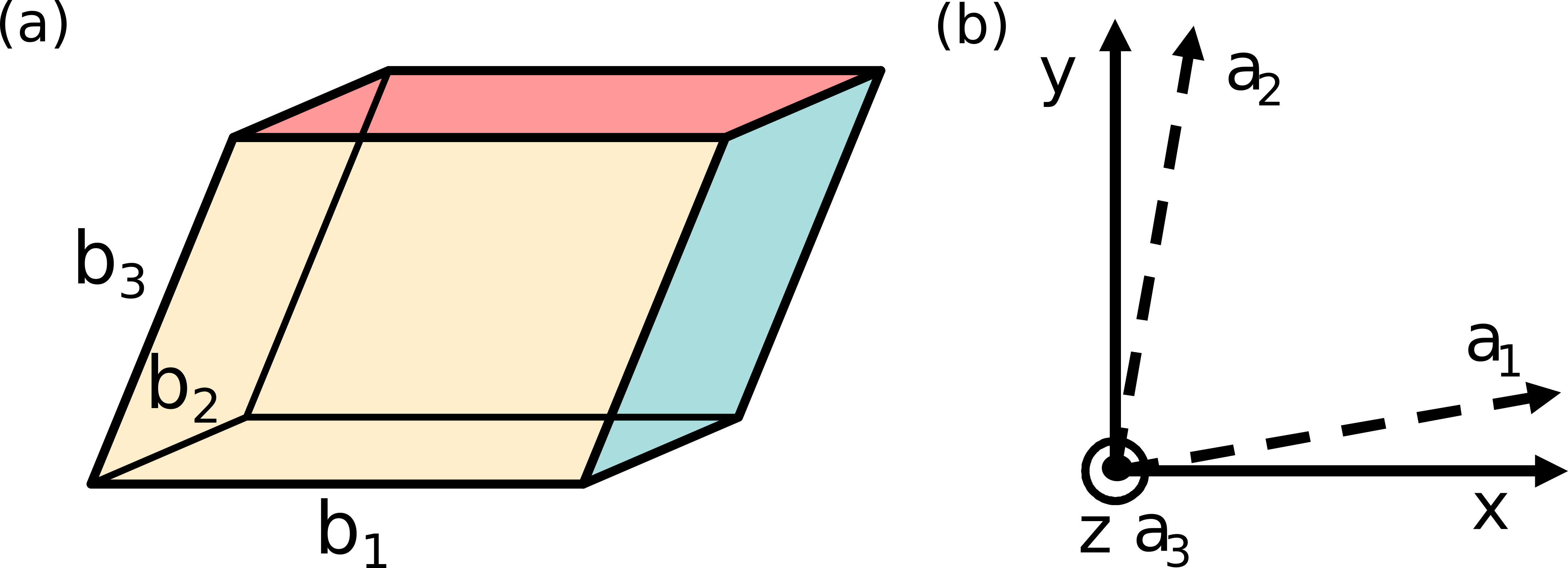
Combining Eqs. (23) and (24) we have
| (25) |
To simplify this further we need to show that is symmetric under interchanging any two indices. This is clearly satisfied for , however, it is less obvious for . From Eq. (19), we see that must hold and thus also should be satisfied. This can be explicitly verified from , which is symmetric as long as is sufficiently smooth function. To show that the tensors are also symmetric under interchanging the other indices, we consider:
| (26) |
Then it must also hold that the and tensors are symmetric under interchanging indices and :
| (27) |
We can thus rewrite Eq. (25) as
| (28) |
Therefore, and we finally find:
| (29) |
Appendix B Symmetry of second order currents
Here we study the symmetry of the second-order currents. Similarly to other response phenomena, the second order currents will in general contain both time-reversal even (-even) and time-reversal odd (-odd) components. Here we consider only the time-reversal odd component since this component corresponds to the UMR. In the following will denote the -odd second-order conductivity tensor. Furthermore, we assume the tensor is symmetric under interchanging any two indices. As shown in Appendix A, this holds for the Boltzmann formula that we use in our calculations. It is not clear whether this holds for the in general, thus the symmetry analysis here should be taken to refer specifically to the Boltzmann contribution. The method for the symmetry analysis is analogous to the one used in Ref. Železný et al., 2017. We have implemented the second order symmetry analysis in the open source code Symmetr. Železný (a) All the results shown here are given in a cartesian coordinate system described in Fig. 6(b). Since in the experiment the magnetization always lies in the [001] plane, we consider here only magnetization in this plane. In Table 1 we give the general shape of the for general direction of magnetization within this plane as well as for the [110] and [1-10] directions where the symmetry is higher.
| or |
|---|
To describe the dependence of the second-order currents on magnetization, it is useful to expand the tensor in powers of the magnetization. We consider only the lowest order term since it describes well both the calculations and the experiment:
| (30) | ||||
Here denotes free parameters of the expansion.
Appendix C Calculation description
The calculations utilize the FPLO density-functional theory (DFT) codeKoepernik and Eschrig (1999); FPL for description of the electronic structure. This DFT uses a local orbitals basis set for solving the Kohn-Sham equations. This makes it easy to transform the DFT Kohn-Sham Hamiltonian into a Wannier form, which is needed for the transport calculations. We use the full set of basis orbitals for this transformation, which makes the Wannier Hamiltonian very accurate. This is crucial for the second-order calculations since the second order contributions are very small and very sensitive to small symmetry violations that often exist in Wannier Hamiltonians generated by the more conventional approach based on maximally localized Wannier functions. The transport calculations utilize Wannier interpolation to evaluate the response formula on a tight grid in the reciprocal space. We have implemented the second-order Boltzmann calculation in the freely accessible Linres code.Železný (b) We have also utilized this code for the calculations of the current-induced spin polarization.
The spin-polarization calculations use the following Kubo formula for the esponse tensor (i.e., tensor such that ):Freimuth et al. (2014)
Here, is the spin operator, are the Bloch functions of a band , k is the Bloch wave vector, (k) is the band energy, is the Fermi energy, is the velocity operator and is a quasiparticle broadening parameter that describes the disorder strength. This formula becomes equivalent to the first-order constant relaxation time Boltzmann formula for small (with ), but differs for finite values of . For the value that we consider the formula is close to the Boltzmann formula. We only consider the Boltzmann formula for the second order calculations since the derivation and evaluation of the second-order Kubo formula is much more complex. We note that the Kubo formula (C) describes only the -even part of the Kubo formula. We do not consider here the -odd component since experimentally it is seen that the in-plane SOT has a field-like character and the corresponding current-induced spin-polarization is thus -even. Our test calculations of the -odd component also suggest that it is much smaller than the -even component for realistic values of .
The DFT calculations utilized 12x12x12 k-points and the GGA-PBE potential. The current-induced spin-polarization and the second-order conductivity response calculations use a 400x400x400 k-mesh, which we have confirmed to be sufficient for good convergence. To estimate the value of we calculate the first order conductivity using a conductivity formula analogous to Eq. (C) and choose the so that the conductivity matches the experimental conductivity. This corresponds to 0.05 eV or alternatively to 6.6 fs. In previous calculations of SOT in NiMnSb, a eV was used,Ciccarelli et al. (2016) because the samples used in those experiments had somewhat larger conductivity. We note that our calculations of the current-induced spin-polarization were done for the eV value and have been afterwords rescaled to eV, assuming scaling. This is quite accurate since for theses value of the formula is very close to the Boltzmann formula and thus has scaling.
Appendix D Power dependence and reproducibility
In Fig. 7 we show that, as expected, the background voltage scales linearly with power and that the angular dependence of is independent of the power. In Fig. 8 we show that the results are reproducible between different bars patterned on the same chip.


Appendix E Modeling temperature gradient using Finite Element Method
The system is excited by an ac current passing mainly through the NiMnSb layer which results in Joule heating. The heat scales with the square of the current density and dissipates into surrounding material giving rise to temperature gradients. The out-of-plane temperature gradient drives ANE which contributes to the electrical signal detected in the sample plane. We perform a simulation of heat transfer in the cross-section of our device utilizing the finite element method (FEM) as implemented in COMSOL Multiphysicscom . The software solves the heat equation numerically using an automatically generated triangular mesh with density adjusted to the size of individual domains of the device. The geometry is shown in Figure 9 and consists of the NiMnSb wire (thickness = 37 nm, width = 1 m) deposited on a (In,Ga)As mesa (thickness = 200 nm, width = 1 m). There is also an InP substrate (thickness = 1 m, width= 2 m), a thin MgO capping layer (thickness = 5 nm, width = 1 m), and a He atmosphere included in the simulation.
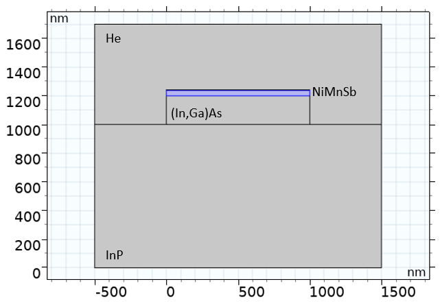
The reference temperature, Tref, is set to 300 K (before the Joule heating takes place). The current density applied to NiMnSb is 1010 or 1011 Am-2. At the boundary of the simulated area the temperature is fixed to Tref or a thermal insulation is assumed (except the bottom boundary again fixed to Tref). These two types of boundary condition correspond to very efficient cooling (transfer of heat to the surroundings) or to extremely poor cooling, respectively. The real system would fall between these two limiting cases. Figures 10 and 11 show the simulated steady-state temperature distribution for the case with boundaries fixed to Tref and with insulating boundaries, respectively.
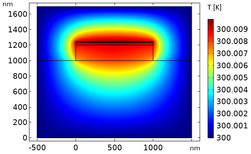
The former case (Fig. 10) is simulated with applied current density of 1010 and 1011 Am-2 but we show the temperature profile only for 1010 Am-2. The 10 times larger current density results visually in the same temperature profile but the maximum temperature increase, T-Tref, is 100 times larger.
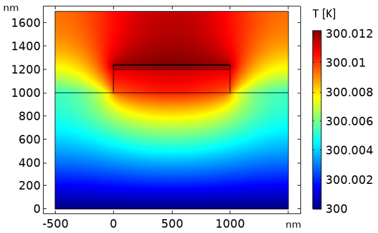
The latter case (Fig. 11) is simulated only with applied current density of 1010 Am-2 and all the heat is dissipated only via the bottom boundary – through the substrate. The out-of-plane temperature gradient is evaluated along a vertical cut-line (along the z-coordinate) running through the middle of the mesa. Figure 12 shows the temperature increase, T-Tref, along the cut-line within the NiMnSb layer (1200 nm to 1237 nm) for the three cases simulated.

As expected, the case with insulating boundaries shows a larger increase in temperature but the dependence on the z-coordinate is the same. The case with 10 times larger applied current shows a 100 times larger increase of temperature which is due to the Joule heating scaling with the square of the applied current density.
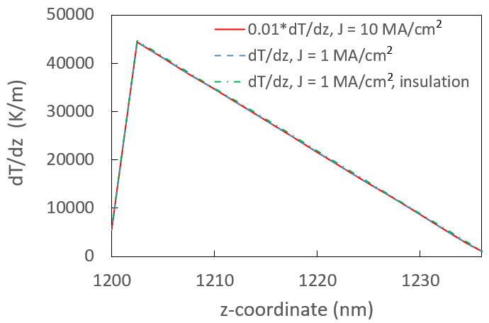
Finally, Figure 13 shows the out-of-plane temperature gradient generating ANE in the NiMnSb wire. It is evaluated simply as a numerical derivative of the temperature given in Figure 12 for the three cases. Note that the gradient decreases linearly in the NiMnSb layer towards the top surface. The efficiency of the cooling (insulating boundaries or fixed temperature) does not affect the gradient so the approximation of the cooling mechanism assumed in our model should not significantly compromise the validity of our numerical results. The main result of the FEM simulation relevant to the experimental device is that the average out-of-plane temperature gradient is of the order of 104 Km-1 for current density of 1010 Am-2.
| [Sm-1] | [Wm-1K-1] | [Jkg-1K-1] | [kgm-3] | |
|---|---|---|---|---|
| MgO | 0 | 200Slack (1962) | 900MgO | 3600 |
| NiMnSb | 3.3e6 | 23Gardelis et al. (2004) | 420Klicpera et al. (2020) | 7600 |
| InGaAs | 1.43e4 | 200Carlson et al. (1965) | 300InG | 5500 |
| InP | 0 | 68InP | 310InP | 4800 |
| He | 0 | 0.15He (2) | 5200He (2) | 145 |
Our FEM results depend on the material parameters used. We have measured the electrical conductivity of the individual layers at room temperature. The room temperature thermal conductivity and heat capacity parameters of our films are estimated based on literature as listed in Table 2. In case of NiMnSb they are estimated based on related materials.Gardelis et al. (2004); Klicpera et al. (2020) The thermal conductivity is underestimated, considering the metallic character of the film, so we report an upper estimate of the thermal gradient. The results are obtained for a steady state so there is no significant dependence on the heat capacity or mass density. (We estimate the mass density based on the molar masses and unit cell volume.)