All-passive multiple-place optical phase noise cancellation
Abstract
We report on the realization of delivering coherent optical frequency to multiple places based on passive phase noise cancellation over a bus topology fiber network. This technique mitigates any active servo controller on the main fiber link and at arbitrary access places as opposed to the conventional technique, in which an active phase compensation circuit has to be adopted to stabilize the main fiber link. Although the residual fiber phase noise power spectral density (PSD) in the proposed technique turns out to be a factor of 7 higher than that of in the conventional multiple-access technique when the access place is close to the end of the fiber link, it could largely suppress the phase noise introduced by the servo bumps, improve the response speed and phase recovery time, and minimize hardware overhead in systems with many stations and connections without the need of the active servo circuits including phase discriminators and active compensators. The proposed technique could considerably simplify future efforts to make precise optical frequency signals available to many users, as required by some large-scale science experiments.
Atomic optical clocks have rapidly grown in the last decade and are proving to be a powerful tool for investigation of fundamental and applied physics [1, 2, 3, 4, 5]. Precision clock networks are of particular interest in precision measurements and fundamental physics tests, such as general relativity, temporal variation of the fundamental constant [6], searching for dark matter, gravitational waves and physics beyond the Standard Model [7, 8, 9, 10], as well as providing innovative quantum technologies for other branches of science [11]. Most of the applications mentioned above require high-precision clock networks with multiple places over fiber links. To achieve this aim, active compensation schemes as first demonstrated in 1994 by Ma et al. have been proposed to cancel the fiber-induced phase drift and implement highly stable optical frequency distribution [12], which generally utilizes the phase error from a round-trip probe signal to achieve the feedback control of a voltage-controlled oscillator (VCO) via a servo controller [12]. One intriguing question is how to distribute a reference optical frequency to many users simultaneously in a cost-effective and robust way.
In the past years, many works have demonstrated that coherence optical phase can be delivered to multiple users with the help of servo controllers. Grosche et al. have first proposed and demonstrated to extract the ultrastable signal for multiple users along the active phase stabilized main link [13], enabling to tap the fiber anywhere with the same precision level as that achieved at the main link output. Alternatively, a branching optical fiber network with phase noise correction at each output end has been proposed and experimentally demonstrated [14, 15]. All these existing demonstrators for the multiple-access applications have to adopt at least one active servo controller for the main fiber link [16, 13, 17, 18] or for each branch fiber link [14, 15, 19]. Consequently, the overall performance of the above mentioned techniques is mainly dependent on whether the servo controller’s parameters set properly [20]. For example, there will be occasional interruptions where a phase lock temporarily loses lock, corresponding to unpredictable jumps in the optical signals. These interruptions will reduce the effective averaging time to bias the measurement [12]. Moreover, the effect of the servo bumps on the main fiber link will pass to each access place and corrupt the spectral purity received by each place.
In our previous work, we have demonstrated optical frequency transfer with passive phase stabilization over a bus or a ring fiber network [21, 19]. The technique possesses the advantages of an unlimited compensation precision and a fast compensation speed and free from the effect of servo bumps on the spectral purity [21, 19]. However, the feasibility and adaptability of the passive phase noise cancellation technique for the multiple-access application needs to be theoretically and experimentally studied. Therefore, the investigation of the novel multiple-access optical frequency transfer scheme which implement alternative phase correction techniques other than the more commonly used conventional, active, phase correction technique is seeing increasing demand. Improving the robustness and sensitivity of multiple-access optical frequency transfer devices, as well as understanding and characterizing the limitations of the novel multiple-access optical frequency transfer scheme with passive phase correction is an important step towards the goal of heralding a new generation of viable precision optical frequency transfer devices. Theses devices could be employed in the above mentioned applications [1, 2, 3, 4, 5, 6, 7, 8, 9, 10, 11].
In this article, we extend the study of the optical frequency transfer technique based on our previous passive phase correction technique [21, 19], demonstrating its application as a multiple-access optical frequency transfer technique. We experimentally study the optical frequency transfer stabilities, phase noise power spectral densities (PSDs) and accuracies for the two access places at the most symmetric 50/50 km () one and the relative asymmetric 70/30 km one, over a total fiber link of km. In comparison with our previous work [21, 19, 22], in which we have demonstrated multiple-place optical frequency transfer over the star and ring fiber networks with the passive phase noise cancellation technique, here we demonstrated that a high performance multiple-place optical frequency transfer over the widely adopted bus fiber topology with all-passive phase noise cancellation at the access places and the main fiber link. The proposed technique could increase the adaptability to incorporate the optical frequency transfer technique into any existing communication networks with different topologies.
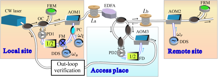
Figure 1 shows the schematic diagram of multiple-place optical frequency transfer with a simple extraction along the passively stabilized main link. The main optical link aims at regenerating a coherent optical phase at the output end of the fiber [21] and at any places along the fiber as the input end of the fiber. The principle of passively stabilizing the main fiber link can be found in [21, 19]. In brief, an ultrastable reference at the local site is upshifted by frequency of with an acousto-optic modulator (AOM) denoted as AOM1 and then injects into the fiber. At the output, the light is downshifted by frequency of with the AOM2 (here ), and part of light is sent back with a Faraday mirror (FRM). The round-trip signal is mixed with the input ultrastable laser using an interferometer consisting of an optical coupler (OC) and another FRM. The beatnote radio frequency (RF) signal is twice the sum of the AOMs’ frequencies and exhibits the round-trip phase noise, , with , where and are the noise of the fiber spans of length of and , respectively. Afterwards, we divide the beatnote with a factor of 2 and then mix the divided signal with an assistant frequency of . The lower sideband of the mixed signal, , is used. Afterwards, the mixed signal together with is fed into the electrical port of the AOM1. Finally at the output end, the phase fluctuations of the optical frequency are automatically cancelled.
At each access place, the configuration is similar with the one presented in [13], at a distance from the input end and from the output end, a optical coupler is adopted to extract both the forward and backward signals from the main fiber. The forward signal can be expressed as,
| (1) |
Similarly, the backward signal has a form of
| (2) |
The beatnote frequencies between and and between and , result in the same frequency of with the phase fluctuation . The signal is divided by a factor of 2, filtered, and drives an AOM (AOM3) in order to correct for the frequency and phase fluctuations of the forward signal. The forward signal after passing through the AOM3, is thus downshifted to,
| (3) |
A similar phase noise cancelled signal can be obtained on the backward extracted signal with an opposite frequency shifter. Thus, the phase noise of the remote site and the access sites are automatically cancelled.
As demonstrated by Williams et al., the phase noise rejection capability is limited by the propagation delay [23]. The residual phase noise PSD, , at each access place in terms of the single-pass free-running phase noise PSD, , and the single-pass fiber link propagation delay, , by compensating the forward optical signal can be expressed as [23, 22],
| (4) |
Note that, in comparison with the conventional multiple-access technique, the phase noise rejection capability of both the conventional and proposed techniques is proportional to and the uncompensated single-pass fiber phase noise PSD, . Although, the residual fiber phase noise PSD in the proposed technique turns out to be a factor of 7 worse than that of in the conventional multiple-access scheme at the output of the fiber link () [16, 19], it could largely suppress the phase noise introduced by the servo bumps (see Fig. 2), which could significantly increase as the increase of the fiber link [24], and simplify the hardware overhead in systems with many stations and connections [21].
We implement the proposed extraction scheme in Fig. 1 on a 100 km fiber link. The signal source that has been adopted in this experiment is a narrow-linewidth optical source (NKT X15) at a frequency of near 193 THz with a typical linewidth of 100 Hz. At an arbitrary access place, a optical coupler (coupling ratio 50%: 50%) is used to tap both forward and backward lights. To demonstrate the phase noise rejection capability at any places along the fiber link, we choose two representative places, which are at the most symmetric one, 50/50 km (), and the relative asymmetric one, 70/30 km. To compensate the total loss of 23 dB of the 100 km fiber link system, we implement a home-made bidirectional Erbium-doped fiber amplifier (EDFA) at the middle of the fiber link. The angular frequencies at the local and remote sites are MHz, MHz and MHz, respectively. The AOM1 is simultaneously supplied by two angular frequencies of MHz and MHz, and the AOM3 is supplied by the angular frequency of MHz. Consequently, the beatnotes between the input and extracted sites have a frequency of MHz. This beatnote is recorded simultaneously with a dead-time free counter with a gate time of 1 s and non-averaging -type operation. At the same time, we implement the phase noise measurement by feeding the heterodyne beatnote signal together with a stable frequency reference to a phase detector. The phase fluctuations at the phase detector output are measured with a fast Fourier transform (FFT) analyzer [22, 25].
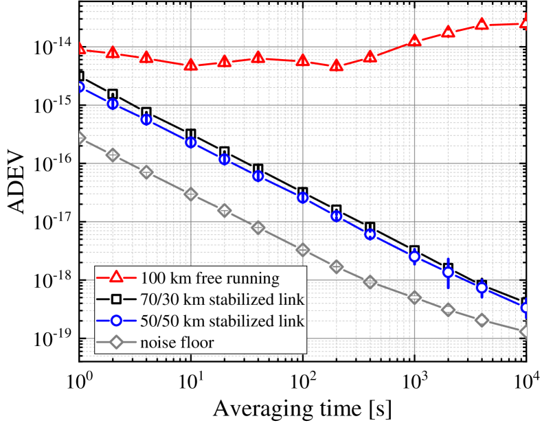
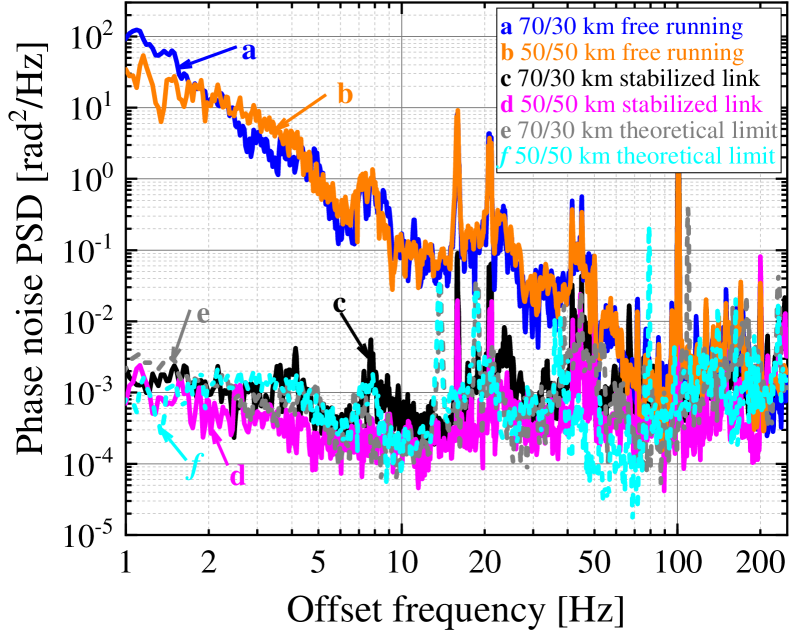
Figure 2 shows the phase noise power spectral densities (PSDs) of the stabilized 70/30 km access place (c, black curve) and the stabilized 50/50 km access place (d, magenta curve), respectively. The phase noise PSDs of the free-running 70/30 km access place (a, blue curve) and the 50/50 km access place (b, orange curve) are also shown. The free-running curve is typical for optical fibre links, with a noise of approximately radHz at 1 Hz for the 70/30 km access place, scaling down with a slope of about , and reaching around radHz after 100 Hz. Their noises of the free-running 70/30 km (a, blue curve) and 50/50 km access places (b, orange curve) slightly differ because the two measurements are performed at different times. At the same time, both passive phase stabilized cases are also very similar with the phase noise PSDs about radHz between and Hz. We can clearly see that the noise correction is limited by the main fiber propagation delay approximately Hz, which is compatible with the theoretical bandwidth of 189 Hz given by . This limit is the same for both access places because the bandwidth of the extraction is limited by the longer delay, namely the main fiber link delay [16]. More importantly, we can clearly see that compared with the conventional multiple-access optical frequency transfer technique [13, 14, 15], the strong servo bumps are effectively suppressed in our passive phase noise cancellation technique as observed in our previous work [19, 21, 22].
Figure 3 displays the fractional frequency stability of the free-running and passively stabilized configurations, calculated from -type data with overlapping Allan deviation (ADEV). The stability of the 70/30 km (50/50 km) access place is () at 1 s averaging time, decreases as a slope of approximately and reaches a floor of approximately () at s. As calculated by Eq. 4, the ratio of the stability of the km and km places should be . In our experiment, we also obtain the ratio of (). As a comparison, we also measured the noise floor for the access output as displayed in Fig. 3. The long-term stability is mainly attributed to the thermal noise on uncompensated fibre paths, due to imperfect length adjustment and thermal stabilisation in the extraction optical set-up, or in the main fiber link [22, 25]. Compared with our previous work in which we characterized the system performance at the output of the main fiber link [21], the ultrastable laser can be thus transferred through the secondary and main links without significant degradation.
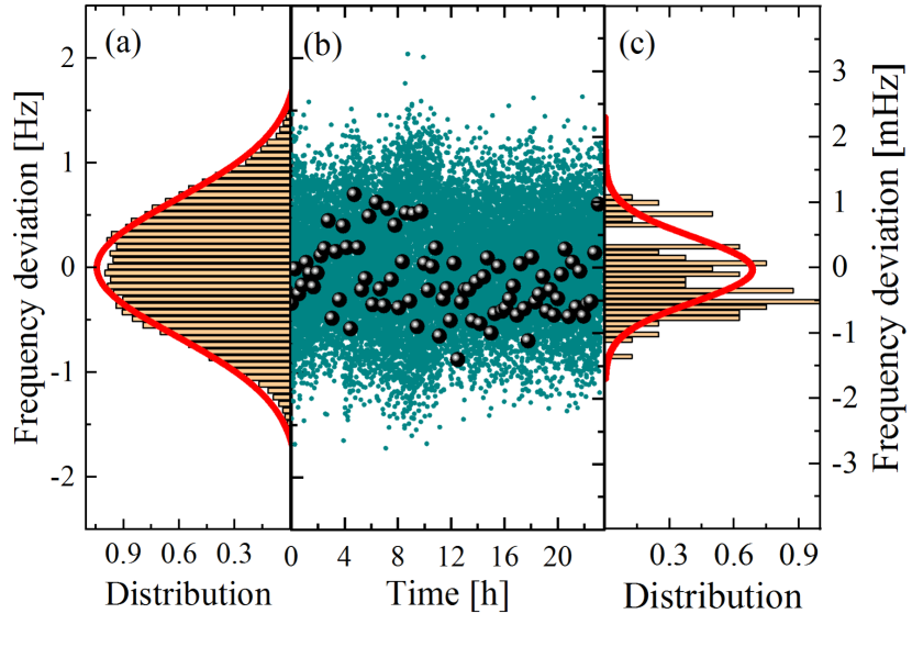
Complementary to the characterization of the stability and phase noise, the accuracy has to be throughout-fully examined by calculating the mean value of the end-to-end beatnote frequency offset. Figure 4(b) shows the frequency deviation of the beatnote’s data for the 70/30 km access place, recorded with a 1 s gate time and -type counters, over successive 84,014 s (green point, left axis) and the arithmetic mean of all cycle-slip free 1,000 s intervals (black dots, right axis). Histograms (brown bars) and Gaussian fits (red curves) of the frequency deviation for the access place after 70 km are also illustrated in Fig. 4(a) and (c). According to the Gaussian fit in Fig. 4(c), the calculated results demonstrate that the mean frequency is shifted by -28.9 Hz (). The standard deviation of the 1,000 s data points is 493 Hz (), which is a factor of 1,000 smaller than the ADEV at 1 s as expected for this -type evaluation. Considering the long-term stability of frequency transfer as illustrated in Fig. 3, we conservatively estimate the accuracy of the transmitted optical signal as shown in the last data point of the ADEV, resulting in a relative frequency accuracy of .
Adopting the same procedure, the mean frequency offset and the standard deviation for the 50/50 km place were calculated using the 1000 s point with the total 89,690 -type counter data to be 52.2 Hz () and 454 Hz (), respectively. Taking into account the long-term ADEV at 10,000 s of the data set for the 50/50 km access place of , we conservatively estimate that the mean frequency offset is with a statistical uncertainty of for the 50/50 km access place. We can conclude that there is no systematic frequency shift arising in the all-passive multiple-place phase noise cancellation setup at a level of a few .
In summary, we have presented a new method, making a stable optical frequency available at any arbitrary access places along the fiber link with passive phase noise cancellation. In comparison with previous work, here we demonstrated that a high performance multiple-place optical frequency transfer over the widely adopted bus fiber topology with the open-loop design, mitigating some technical difficulties in conventional active multiple-access phase noise cancellation. We experimentally demonstrate transferring of optical frequency to two different access places. After being compensated, delivering an optical frequency to different places with the relative frequency instability in terms of ADEV measured by the -mode frequency counter can be as low as at 1 s and at 10,000 s. The frequency uncertainty of the light after transferring through the fiber relative to that of the input light is a few for the access places over the 100 km fiber link.
Funding. This research was supported by the National Natural Science Foundation of China (NSFC) (61905143, 61627817).
Disclosures. The authors declare no conflicts of interest.
References
- [1] B. J. Bloom, T. L. Nicholson et al., \JournalTitleNature 506, 71 (2014).
- [2] E. Oelker, R. B. Hutson et al., \JournalTitleNature Photonics 13, 714 (2019).
- [3] W. F. McGrew, X. Zhang, R. J. Fasano et al., \JournalTitleNature 564, 87 (2018).
- [4] N. Huntemann, C. Sanner et al., \JournalTitlePhysical Review Letters 116, 063001 (2016).
- [5] S. M. Brewer, J.-S. Chen et al., \JournalTitlePhysical Review Letters 123, 033201 (2019).
- [6] R. H. Parker, C. Yu, W. Zhong et al., \JournalTitleScience 360, 191 (2018).
- [7] A. Derevianko and M. Pospelov, \JournalTitleNat. Phys. 10, 933 (2014).
- [8] K. Van Tilburg, N. Leefer et al., \JournalTitlePhys. Rev. Lett. 115, 011802 (2015).
- [9] A. Arvanitaki, J. Huang et al., \JournalTitlePhys. Rev. D 91, 015015 (2015).
- [10] L. Hu, N. Poli et al., \JournalTitlePhys. Rev. Lett. 119, 263601 (2017).
- [11] M. S. Safronova, D. Budker et al., \JournalTitleRev. Mod. Phys. 90, 025008 (2018).
- [12] L.-S. Ma, P. Jungner, J. Ye, and J. L. Hall, \JournalTitleOpt. Lett. 19, 1777 (1994).
- [13] G. Grosche, \JournalTitleOpt. Lett. 39, 2545 (2014).
- [14] S. W. Schediwy et al., \JournalTitleOptics Letters 38, 2893 (2013).
- [15] L. Wu, Y. Jiang, C. Ma et al., \JournalTitleOpt. Lett. 41, 4368 (2016).
- [16] A. Bercy, S. Guellati-Khelifa et al., \JournalTitleJ. Opt. Soc. Am. B 31, 678 (2014).
- [17] P. Krehlik, L. Sliwczynski, L. Buczek, and M. Lipinski, \JournalTitleIEEE Transactions on Ultrasonics, Ferroelectrics, and Frequency Control 60, 1804 (2013).
- [18] G. Grosche, \JournalTitleGerman patent application DE 10 (2010).
- [19] L. Hu, X. Tian, G. Wu et al., \JournalTitleJournal of Lightwave Technology 38, 3644 (2020).
- [20] K. H. Ang et al., \JournalTitleIEEE Transactions on Control Systems Technology 13, 559 (2005).
- [21] L. Hu, X. Tian et al., \JournalTitleOpt. Lett. 45, 4308 (2020).
- [22] L. Hu, X. Tian et al., \JournalTitleJournal of Lightwave Technology 38, 5916 (2020).
- [23] P. A. Williams et al., \JournalTitleJ. Opt. Soc. Am. B 25, 1284 (2008).
- [24] S. M. Raupach, A. Koczwara et al., \JournalTitlePhys. Rev. A 92, 021801 (2015).
- [25] X. Tian, L. Hu, G. Wu, and J. Chen, \JournalTitleJournal of Lightwave Technology 38, 4270 (2020).