Revisiting the Memristor Concept within Basic Circuit Theory
Abstract
In this paper we revisit the memristor concept within circuit theory. We start from the definition of the basic circuit elements, then we introduce the original formulation of the memristor concept and summarize some of the controversies on its nature. We also point out the ambiguities resulting from a non rigorous usage of the flux linkage concept. After concluding that the memristor is not a fourth basic circuit element, prompted by recent claims in the memristor literature, we look into the application of the memristor concept to electrophysiology, realizing that an approach suitable to explain the observed inductive behavior of the giant squid axon had already been developed in the 1960s, with the introduction of “time-variant resistors.” We also discuss a recent memristor implementation in which the magnetic flux plays a direct role, concluding that it cannot strictly qualify as a memristor, because its curve cannot exactly pinch at the origin. Finally, we present numerical simulations of a few memristors and memristive systems, focusing on the behavior in the plane. We show that, contrary to what happens for the most basic memristor concept, for general memristive systems the curve is not single-valued or not even closed.
Index Terms:
Circuit theory, Memristive Systems, Memristor, Numerical Simulations.I Introduction
The concept of memristor was first introduced by Chua [1] in 1971 as a two-terminal circuit element establishing a relationship between the charge (which is the integral of the current) and the integral of the voltage (which can also be defined as “flux linkage”). Already in this pioneering paper, along with the detailed definition of the memristor and of its properties, a claim appeared that the memristor was to be considered as basic as the three classical circuit elements: the resistor, the capacitor, and the inductor.
Here we focus on evaluating such a claim and on determining the essential nature of the memristor within circuit theory.
The well-established basic elements in circuit theory are the inductor, the capacitor, and the resistor. Such elements introduce independent relationships between pairs of circuit quantities. In their most direct implementations, they can also be seen as expressions of different physical laws. Citing the classical book by Desoer and Kuh [2], we report verbatim the definition of the inductor: a two-terminal element will be called an inductor if at any time its flux and current satisfy a relation defined by a curve in the plane. The essential idea is that there is a relation between the instantaneous value of the flux and the instantaneous value of the current. It is important to point out that from the point of view of circuit theory and analysis the flux is the flux linkage, i.e., the time integral of voltage, which is an actual circuit quantity. In the particular case of the classical idealized inductor obtained by winding an ideal thin conductor, such an integral happens to coincide with the magnetic flux linked with the coil, which in turn corresponds to the actual magnetic flux piercing it only in the case of a coil with a single turn. For an inductor, the relationship between the time integral of the voltage and the current can be seen as an expression of Lenz’s law, although this is not the only way to obtain such an “inductive” behavior, which could well be implemented in a more elaborate fashion also in a world without magnetic field (for example with a capacitor and a gyrator).
The capacitance establishes a relationship between the voltage and the integral of the current (i.e., the charge ) described by a curve in the plane. In the particular case of a classical capacitor consisting of two conductors separated by a dielectric, this is an expression of Gauss’ law. Also in this case, we report verbatim from [2]: The basic idea is that there is a relation between the instantaneous value of the charge and the instantaneous value of the voltage .
Finally, the resistance establishes a relationship between the voltage and the current , through a curve on the plane. Linear resistors are implemented through Ohm’s law, i.e., with conductors exhibiting a linear relationship between current and voltage. In [2], the authors write: The key idea of a resistor is that there is a relation between the instantaneous value of the voltage and the instantaneous value of the current. Also on the basis of the examples provided by Desoer and Kuh, this means that such a relation may be independent of the current and constant in time (linear time-independent resistor), dependent on the current but constant in time (non-linear time-independent resistor), independent of the current but time dependent (linear time-dependent resistor), or dependent on the current and on time (non-linear time-dependent resistor).
Within a strict interpretation, this definition does not include many components of general use, which are commonly referred to as resistors because they are characterized by a dissipative behavior and the voltage at their terminals drops to zero whenever the current vanishes (which is equivalent to having a “pinched” relationship, an expression commonly used in the memristor literature).
A very simple example is represented by the incandescent light bulb, which is characterized by a resistance depending on temperature: since the temperature behavior exhibits a delay with respect to the current behavior (as a result of the thermal inertia of the filament) and depends on the ambient temperature, this would not fit any of the resistor definitions by Desoer and Kuh. We will discuss this issue in detail in Sec. II.
Summarizing, each basic element is associated with a single-valued curve relating two electrical quantities ( and for the resistor, and for the inductor, and for the capacitor). Such a curve is in general dependent on time (time-dependent elements), can be time-independent (time-independent elements), or can be just a line (linear elements, and, more in detail, a line with a slope depending on time for the linear time-dependent elements or just a single line for linear time-independent elements).
To make our argument more rigorous, we provide a working definition for the concept of basic circuit element: a basic circuit element, in its simplest implementation, establishes a relationship between two circuit quantities that cannot be reproduced by any single other basic circuit element. By simplest implementation we mean the linear and time-independent case. For example, if two circuit elements are characterized by different physical dimensions, they certainly define independent relationships. Conversely, in the case of a memristor with a constant value, we obtain the same relationship between flux linkage and charge as that implemented by a resistor.
In 1976 Chua and Kang [3] extended the concept of memristor, indicating the memristor as a special case of a class of dynamic systems (memristive systems) for which the following relationships hold:
| (1) | |||
| (2) |
being the vector of the state variables of the system, a generic input quantity and a generic output quantity. In principle and can be arbitrary physical quantities.
In the same 1976 paper, Chua and Kang defined a particular memristive system in which is a voltage and is a current as a current-controlled memristive one-port. Analogously they defined a memristive system in which is a current and is a voltage as a voltage-controlled memristive one-port.
In 2009 Di Ventra et al. [4] analyzed two particular types of memristive systems, one with and and the other with and , defining them memcapacitive systems and meminductive systems, respectively. A Lagrangian-Hamiltonian formalism for the description of such devices was then proposed by Cohen et al. [6] in 2012.
More recently, in 2015, Chua [7] provided a detailed overview, reporting a hierarchy going from a class that is slightly less general than the memristive one-port down to the original 1971 memristor (reclassified as “ideal memristor”).
For the purposes of our discussion, we will not need this more detailed classification (which does not add new contributions to the basic memristor theory, but it is just a more detailed taxonomy) and will refer to the definitions of the 1971 and 1976 papers, limiting ourselves to current-controlled and voltage-controlled memristive one-ports. It is our impression that the 1971 and the 1976 definitions of memristor and memristive systems, respectively, along with the extension to the memcapacitor and meminductor, represent a very clear framework, and that the introduction of further distinctions and/or extensions is not strictly necessary. For example, the “extended memristive device” introduced by Valov et al. [8] is indeed just a circuit in which a memristive system (according to the 1976 definition), a nonlinear resistor (according to the definition by Desoer and Kuh) and a voltage source are present. In addition, we believe that it would be convenient to use the word “memristor” only for the device defined in the 1971 paper by Chua, avoiding its usage for the more general “memristive systems” (such as, for example, the light bulb). Indeed, as we will discuss in Section III, general memristive systems are not guaranteed to exhibit a single-valued characteristic, which was one of the fundamental properties of the original 1971 memristor.
Memristors have received significant attention by the scientific community, both for the analysis of circuit behavior and for possible industrial applications [9],[10],[11],[12]. Such an interest into the memristor was mainly triggered by the 2008 paper by Strukov [13], in which experimental data were reported showing a behavior of a memristive nature for a nanoscale device.
In more detail, a titanium oxide film with a thickness of 5 nm was sandwiched between two metal (platinum) electrodes and was made up of two layers: an insulating layer and a conducting layer (where conduction is due to oxygen vacancies acting as dopants). Such vacancies drift in the presence of an electric field, thereby moving the boundary between the conducting and the insulating layer and thus varying the overall resistance.
In [14], the authors criticize the interpretation of such a device as a memristor on the basis that a “real memristor” should involve magnetic flux. They also state the opinion that the original hypothesized memristor is still missing and probably impossible, while recognizing that a real memristor may in principle be discovered.
The analysis of the memristor nature that we will present in the following leads instead to the conclusion that the device can well be considered a memristor (since, as it will become apparent from our discussion, the magnetic field is not essential, or even relevant, in the definition of the memristor).
In [15] Abraham maintains that the device proposed in [13] is not Chua’s postulate of 1971, while also rejecting the memristor as a new basic circuit element. He sets out to demonstrate the non basic nature of the memristor with an involved argument based on a periodic table of basic elements and on two rules; one inferred from an analogy with the periodic table of chemical elements and the other one from the assumption that the definition of basic elements should be given outside transient conditions. Overall, Abraham points out some of the fundamental problems in the original memristor discussion (such as the ambiguity between the actual magnetic flux and the time integral of the voltage) and provides insightful hints into the nature of the memristor, without, however, making a complete case.
Our analysis, once we have reached in a more direct way the same conclusion as Abraham’s that the memristor is not a fourth basic circuit element, focuses on the intimate nature of a current or voltage-controlled memristive one-port. To this purpose, we provide an extended revisitation and analysis of significant past literature, and discuss the detailed behavior of a few relevant memristive one-ports, with a special focus on the associated curves in the plane. Our final conclusion is that the current-controlled or voltage controlled memristive one-ports, and, specifically, the memristor (“ideal” memristor defined in [1]) can be seen just as generalized resistors. Such a concept was indeed already proposed by Alexander Mauro [16] in 1961, in order to explain the appearance of a reactive component in the differential impedance of the giant squid axon and of the thermistor.
The structure of the paper is as follows: Sec. II contains the main discussion on the basic nature of the memristor and of relevant examples from the literature. It is divided into 5 subsections: in Subsection A we summarize the main defining memristor properties; in Subsection B we provide a clarification about the issue of the flux linkage vs. magnetic flux; in Subsection C we present the reasons why we believe that the memristor is not a basic circuit element; in Subsection D we focus on two enlightening examples in which the appearance of a reactive component of the impedance is explained with the introduction of a generalized resistor concept; and, finally, in Subsection E we perform an analysis of a recently published memristor implementation, pointing out that its characteristic is not rigorously pinched. In Sec. III, we present a few numerical examples useful to clarify the properties of memristors vs. those of more general memristive systems in the and planes. In particular, we focus on the conditions needed to obtain a closed or even single-valued (as in the case of the original memristor definition) curve. Finally, we present our conclusions.
II Basic Discussion
II-A Memristor properties
Let us start from the analysis of the memristor concept that was presented by Chua in his original work [1]: a passive element characterized by a relationship of the type . In that paper, he also made the distinction between a charge-controlled memristor and a flux-controlled memristor for which can be expressed as a single-valued function of the charge or the flux linkage , respectively. Thus, for example, for the simplest form of charge-controlled memristor, we have:
| (3) |
and the voltage across the memristor is:
| (4) |
The term is defined memristance and can be expressed as:
| (5) |
Thus it is actually a differential memristance, because it establishes a proportionality relationship between the differentials of the original quantities ( and ) it is supposed to relate. This is not consistent with the definitions for resistors, capacitors and inductors which directly establish a proportionality relationship between and , and , and and , respectively.
Thus, in order to be perfectly consistent with the definitions for the basic circuit elements, the memristance should instead have been defined as the ratio of the flux linkage (the time integral of the voltage) to the charge (the time integral of the current), i.e., it should coincide with the in the relationship
| (6) |
As acknowledged by Chua himself [1], if has no dependence on , the memristor becomes exactly equivalent to an ordinary linear and time-independent resistor.
Chua also pointed out [1] that the existence of a single-valued relationship between the flux linkage (time integral of the voltage) and the charge was at the basis of the memristor definition, in analogy with the relationships mentioned by Desoer and Kuh for the basic circuit elements. He even presented a design for a tracer for the experimental acquisition of such a characteristic.
Let us now focus on the more general case of current (voltage) controlled memristive systems, defined by (1) and (2) when is a current and is a voltage ( is a voltage and is a current).
The properties that they are expected to
exhibit are:
a) In [17] the authors report that the relationship shows a
pinched hysteresis loop for a periodic
input signal or equivalently, as stated by Chua in [19], all
memristive systems are characterized by the property that a zero output
corresponds to a zero input, i.e., that for we always have ;
b) In [18], Ascoli et al. state: The memristor …
is a two-terminal nonlinear dynamic circuit element obeying a Ohm law
dependent upon the time evolution of its memory state.
c) For the particular case of being only a function of , the area
of the hysteresis loop decreases with frequency and the hysteresis loop
collapses to a single-valued function in the limit of , being
the operating frequency.
Any of these properties is consistent with the memristive system being simply a resistor whose value depends on the internal state vector , on the instantaneous value of the current (for the current-controlled case) and, possibly, on time.
However this does not just correspond to a time-dependent resistor, because, in the commonly accepted interpretation within circuit theory, a quantity is time-dependent if its value has a direct dependence on time, i.e., its partial derivative with respect to time is non zero and there is no other indirect dependence on time.
In the case of the memristor, instead, the memristance depends on variables which are in turn functions of time, therefore it has a zero partial derivative with respect to time (in the case of a “time-independent” memristor), but a non-zero total derivative with respect to time.
In 1961 Mauro [16] introduced the concept of a “time-variant” resistor, an element whose resistance “varies intrinsically with time by virtue of the fact that the physical state of the element changes with time,” while a time-dependent resistor is an element whose resistance varies “as an independent function of time” (in accordance with the definition by Desoer and Kuh). In Subsections C and D we provide a detailed discussion of this concept.
II-B Magnetic flux and flux linkage
As already mentioned, is just the time integral of the voltage (i.e., the flux linkage), which is a relevant quantity in circuit analysis (while the magnetic flux is not an actual circuit quantity, except in the case of ideal inductors, when it coincides with or is proportional to the flux linkage). This is fully consistent with the definition given by Chua in the first page of his original memristor paper of 1971 [1]. However, in Sec. 4 of the very same paper, Chua, trying to provide a more general interpretation of the memristor, in terms of a quasi-static solution of Maxwell’s equations, states that the surface integral of the magnetic flux density is proportional to the flux linkage. The problem is that such a flux linkage (originally defined relative to an inductor and equal to the magnetic flux linked by each loop of the inductor multiplied by the number of loops) is not, except for the case of an ideal inductor, the flux linkage used in the first part of the paper for the definition of the memristor, i.e., the time integral of voltage.
This discrepancy is at the origin of the ambiguity (integral of the voltage vs. actual magnetic flux) in the meaning of that may have contributed to some involved arguments on the nature of the memristor which can be found in the literature and to the search for a memristor relating the actual magnetic flux with the charge, which turns out to be a somewhat ill-posed problem: in order to make the integral of voltage proportional to the actual magnetic flux an inductance must be present, which will then lead to a curve that cannot be exactly pinched in the origin.
In some papers the meaning of flux linkage used in the original memristor definition appears to have been completely forgotten, and the memristor is presented as a circuit element relating charge and “magnetic flux” [25, 26].
More in general, circuit theory is indeed a special case of Maxwell’s equations only as long as we consider classical physics and we limit ourselves to electromagnetic phenomena. If other effects (e.g. chemical, thermal, etc.) are included or if quantum mechanical effects are taken into account, a multiphysics approach is needed. In the introduction we have already mentioned the case of the thermistor (which requires the inclusion of the heat transport equations) and of the axon (which requires the inclusion of ion transport equations). Another example can be that of quantum capacitance [27, 28, 29], which arises as a consequence of the quantum confinement energy and the relationship between the chemical potential and the charge.
If we consider the proper definition of , the based device presented in [13] can indeed be defined a memristor, as we had anticipated, because it is a resistor whose value is a function of the charge that has flowed through it, and thus of the time evolution of the current, which makes it a specific type of time-variant resistor, exhibiting the memristor properties defined in [1].
II-C Matrix representation of circuit elements
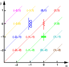
In [33] Chua introduces a matrix representation of the circuit elements, which we summarize in Fig. 1. In more detail, each element of the matrix can be identified by the pair , where and indicate the column and row of the element, which correspond to the order of the time derivative of the voltage and of the current, respectively. An element located in the column and in the row relates the time derivative of order of the voltage to the time derivative of order of the current through a single-valued function. Thus, moving along the main diagonal, it is possible to identify the resistor and the memristor, which is in the position (), while moving along the diagonal right below the main one we can identify the capacitor and the memcapacitor (), and along the diagonal above the main one we find the inductor and the meminductor () [4].
If one were to assume that each element of the matrix corresponds to an independent basic circuit element, also the memcapacitor and the meminductor would be as basic as the resistor, the capacitor, the inductor, and the memristor.
However, it is apparent that it cannot be so, because, first of all, in the linear case all the elements of the same diagonal do coincide, which is by itself evidence that independent basic circuit elements cannot exist along the same diagonal. Furthermore, considering the most direct implementation, each diagonal is associated with a specific physical law: Gauss’s law for the diagonal below the main one, Ohm’s law for the main diagonal, and Lenz’s law for the diagonal above the main one. Indeed also the memristor, as the resistor, is in the end a dissipative element, and is therefore an expression of Ohm’s law. The dissipative nature of the memristor was realized also by Di Ventra and Pershin [5], who point out that, as a result of such dissipative behavior, the memristor violates the time-reversal invariance. This intrinsically resistive nature of the memristor has sometimes been overlooked because of the mistaken association with the magnetic flux instead of with the time integral of the voltage.
The previously mentioned interpretation of as the actual magnetic flux appears to be also at the origin of the choice by Wang of the memristor, the memcapacitor and the meminductor as the elements for his “basic element triangle” [35] that he proposed after recognizing the inconsistency of assuming the memristor as a fourth basic circuit element. Such a formulation appears to be reasonable and free from the contradictions of the four basic element assumption. It is also consistent with the position of the memristor, memcapacitor and meminductor in three different diagonals of Fig. 1. Wang reaches this conclusion mainly because he considers the flux more fundamental than the voltage, a somewhat understandable argument if were the actual magnetic flux, which however is not, as we have already pointed out.
In addition, as previously discussed, the memristance is defined exactly as a resistance with more general properties, instead of the ratio of the flux linkage to the charge (which would still coincide with a resistor in the linear, time-independent case). The same is true for the memcapacitor, defined by [5] (instead of ) and for the meminductor, defined by [5] (instead of ).
Thus it is far simpler to just generalize the definitions of the circuit elements provided by Desoer and Kuh, by including time-variant elements, as proposed by Mauro for the resistor, and to keep the resistor, the capacitor and the inductor as the basic circuit elements (which in this way would also include all the properties of the memristor, memcapacitor and meminductor).
Possibly, novel basic elements could be associated to more external diagonals, even though their practical realization is apparently far from being conceived, and a discussion on this is outside the purpose of the present work.
Overall our conclusion is that a fourth basic circuit element does not exist, and that the memristor can be seen simply as a generalization of the resistor, a time-variant resistor, according to the definition given by Mauro in 1961, which we will discuss in detail in the next subsection. A further generalization of the time-variant resistor concept by Mauro, introducing also a direct dependence on time, covers the most general definition of a memristive current controlled (or voltage controlled) one-port provided by Chua and Kang [3], in which the value of the memristive one-port is a generic function of a set of state variables, the current (or the voltage in the case of a voltage controlled memristive one-port), and, possibly, time.
As long as we assume a reasonable boundedness condition for the memristance (as suggested by Chua in [36] and in [37] to prevent the problems pointed out by Pershin and Di Ventra in [38]), the fact that the curve in the plane is pinched is simply equivalent to stating that there is no energy storage in the device and, thus, that the device is purely dissipative, i.e., a resistor.
II-D Time-variant resistors
It is now appropriate to go back to the example we mentioned in the introduction: the filament of the incandescent light bulb, which is one of the simplest cases that do not fit into the textbook definition of resistor that we quoted at the beginning.
Already in 1961, Alexander Mauro [16], realized the difference between an incandescent light bulb and a time-dependent resistor, and defined it as a “time-variant” resistor, as mentioned at the end of Subsection A.
In particular, Mauro provided analytical evidence that a circuit containing a thermopositive element (i.e., an element whose resistance increases with temperature) such as an incandescent light bulb exhibits a differential impedance of capacitive nature (as a consequence of the delay in the temperature response to current variations), while with a thermonegative element a differential impedance of inductive nature would appear. In the paper by Mauro this was introduced to provide a physical justification of the so-called “anomalous impedance,” which had been observed in giant squid axons [20]. Indeed, early measurements of the AC impedance of the giant squid axon had revealed a significant inductive component, which could not be explained as a result of magnetic energy storage, due to the absence of a large enough loop. This is the reason why Cole [20] mentioned that this property had been found shocking, but he accepted it, and correctly attributed it to properties of the membrane (from the observation that it could not be associated with a flow of current parallel to the axon, due to the fact that an asymptotic inductance value was reached when increasing the distance between the electrodes along the axon). Mauro, with the case study of the temperature-dependent resistor, was able to present a clear example of how a time-variant resistor (a resistor whose value depends on state variables, which in turn depend on time) may exhibit a differential inductive behavior. Then in 1965 Cohen and Cooley [21] performed a numerical solution of the Nernst-Plank equations for ionic transport through a thin permeable membrane, finding, for this specific physical system, an inductive behavior, as shown in their Figs. 5 and 6, analogous to that derived by Mauro for a generic thermonegative element. Thus, by 1965 the presence of an inductive component in the impedance of a membrane, and therefore of an axon, had been understood and explained without requiring the presence of any magnetic field.
It is therefore surprising that in a recent paper [22], the presence of the axon inductance is reported as a problem that had remained unsolved for 70 years and that for the same amount of time had been associated with an “enormous magnetic field”.
In general a magnetic field is not needed to produce an inductance-like behavior, because it can simply arise as a result of inertia: inertia of carrier motion for the kinetic inductance [23], thermal inertia for thermonegative elements, delay associated with ionic diffusion for the axon inductance, etc. It is however important to point out that not all of these three examples are of a memristive nature: while in the second and the last example there is no energy storage, in the first example energy is stored in the form of kinetic energy and can be returned to the circuit. Therefore in the case of kinetic inductance we are dealing with an actual inductance which is not associated with a pinched characteristic, while in the other two cases there is no energy restitution and we have a memristive behavior.
The authors of [22] redefine the time-variant resistors of the Hodgkin-Huxley [24] paper as time-invariant memristors (time-invariant memristive systems, on the basis of the definitions we decided to use in the introduction, since, as we will show in Sec. III, they are not characterized by a single-valued curve in the plane) and then proceed to the calculation of the differential impedance of the overall circuit, finding the expected inductive component.
However, the same calculation could have been performed without renaming them, and following, for example, the approach used by Mauro to treat the temperature-dependent resistor. Furthermore, Mauro provided a clear physical explanation of the appearance of an inductance behavior, while in [22] the inductance is the result of a long and involved analytical calculation, without direct physical insight.
Thus, both definitions, time-variant resistor and memristive system, are acceptable and, if properly handled, lead to the same results.
II-E Magnetic core memory device - memristor
In relationship to the search for a memristor connecting directly the charge with the magnetic flux (instead of the time integral of the voltage), Wang et al. [30] have recently published a paper in which they present a device that they define a “real memristor”. Such a device is based on a conducting wire going through a magnetic core: if a rectangular current pulse is applied to the wire, the resulting magnetic field rotates the core magnetization, which in turn leads to a variation in time of the magnetic flux, and thus to an induced voltage. This is exactly the readout process of the old magnetic core memories [32], with the only difference that, while in core memories two separate loops were used (one to inject the current and one for the readout), Wang et al. use a single loop. They find a relationship between the magnetic flux and the charge, and, in particular, a pinched current-voltage relationship (as typical for memristors).
However they do neglect the voltage induced as a result of the geometrical self-inductance of the loop, i.e., the inductive effect associated with the magnetic flux variation directly produced by the input current. In the case of square current pulses, the authors state explicitly that they have filtered out (by reducing the oscilloscope bandwidth) the “transient spike,” due to such inductance, which they define as “parasitic” (the spike is indeed visible in the experimental data of their Fig. 10). If instead we consider a sinusoidal excitation, as in (12) of [30], there is another term to be included, again due to the geometrical loop inductance, which is in quadrature with the one of [30]. Such inductance is indeed not “parasitic,” because it is the source of the very same connection between magnetic flux variation and induced voltage that leads to the in-phase term. The in-phase term is the result of the flux variation due to the magnetization lining up with the driving magnetic field created by the injected current, while the quadrature term is the result of the flux variation due to the change of such a driving magnetic field. The alignment of the magnetization is the consequence of the dissipative effect connected with the Gilbert term [31] thus leading to a time-variant resistive component (the memristor-like part). Depending on the waveform and on the magnetic core characteristics, the in-phase term may be much larger than the quadrature term, but the ratio of their amplitudes must in any case be finite: if the inductive component should vanish, the same would happen for the dissipative “memristive” component. Thus the -memristor is not rigorously a memristor, because its characteristic curve cannot be exactly pinched.
Furthermore, the authors of [30] in their Fig. 9 report curves for the voltage and the current as a function of time that are not consistent with the plot in the plane and with the experimental results at the top of Fig. 9. Indeed, in the plot reporting the time behavior of the current and the voltage, the current changes sign exactly when the voltage pulse ends. In such a case, and in any other case in which the current is reversed after the voltage pulse ends (as in the experimental results of Fig. 10), the curve on the plane would not look like the one reported, but would consist of a collection of segments without a hysteresis cycle: there would be a horizontal segment corresponding to the current step, then a vertical segment corresponding to the increase and decrease of the voltage at constant current, and then again a horizontal segment reaching the negative current value, followed by a behavior symmetric with respect to that during the positive current pulse.
Curves with hysteresis such as the one reported by the authors of [30] for the plane and in their experimental results at top of their Fig. 9 are possible only if the current is reversed before the voltage pulse ends (which is also consistent with the frequencies they report for the experimental result and the duration of the voltage pulses in Fig. 10).
In order to further clarify the properties of different types of memristive one-ports, in the next Section we present a few numerical examples for relevant cases: the thermistor, the axon, and a memristor (according to a strict interpretation of the 1971 definition by Chua) made up of resistors and charge controlled switches. For all the examples, we report the associated curve and discuss the conditions under which such a curve is single-valued.
III Memristive Circuit Models
A memristive functionality can be implemented in many different ways, exploiting a variety of different physical systems, even relatively exotic ones [39], since all that is needed is a dissipative effect and a mechanism that can vary the resistance under the control of a state variable.
Here we focus on the analysis of a few simple but meaningful examples.
We start with a numerical analysis of the thermistor, which is the first memristive device that was studied by Mauro in 1961 to provide an example of how a differential impedance with a reactive nature can appear in the absence of actual physical capacitors or inductors and of energy storage. We consider the thermistor model of [3], which is based on the following equations, including the dependence of the thermistor resistance on temperature (which is the state variable), as well as the time evolution of temperature as a function of the heat capacitance, the thermal resistance to the outside environment, and the dissipated electrical power.
| (7) | |||
| (8) | |||
| (9) |
where mW/∘C, k, K, K, mJ/K.
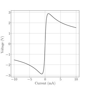
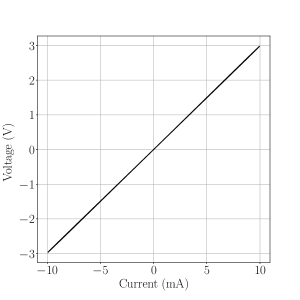
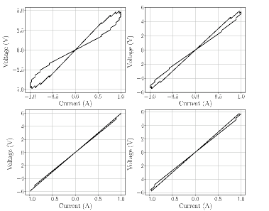
We first report (Fig. 2) the curve obtained by cycling the current in the low-frequency limit (1 Hz), which corresponds to the result in Fig. 2 of [3]: in this case the hysteresis disappears and a single-valued relationship between voltage and current is established, since dynamical effects due to the delayed response of the state variable (the temperature) to the time behavior of the dissipated electrical power are negligible at such a low frequency, which is much smaller than the reciprocal of the relevant time constant of the system.
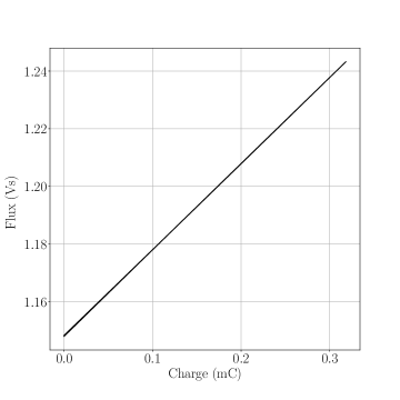
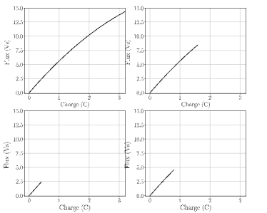
In Fig. 3, we report the associated curve in the plane, which, in this particular case without hysteresis, is single-valued. Therefore at vanishingly small frequency the thermistor does have a property (an unambiguous definition through a curve in the plane) that was reported as a fundamental characteristic of a memristor in [1]. Such an unambiguous relationship between the two defining quantities (e.g., voltage and current in the case of the resistor) is also at the basis of the basic circuit element definitions by Desoer and Kuh [2].

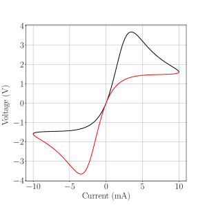
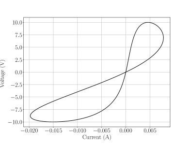
We then consider (Fig. 4) the curve of the same device obtained cycling the current at a higher frequency (0.01 Hz): in this case a hysteresis appears, as a result of the delay of the thermal response. The red portion of the curve corresponds to the descending half-period of the current, while the black portion is relative to the ascending half-period. It is to be noted that neither the ascending nor the descending branches are symmetric around the origin, which implies that a different amount of flux linkage is transferred in the first and in the third quadrant.
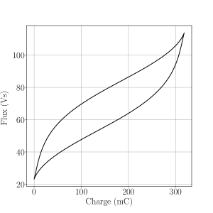
A complementary asymmetry is present in the other branch, which leads to a hysteresis in the plane. The curve in the plane is not single-valued, neither with respect to nor with respect to , although it is closed (Fig. 5). As a consequence, at such a frequency this thermistor model does not exhibit the properties of the memristor defined of 1971, although it still belongs to the more general category of time-variant resistors [and fits in the later definition (1976) of memristive systems].
If we cycle the current at a relatively high frequency (compared to the reciprocal of the characteristic time constant of the device), the hysteresis disappears and we obtain a substantially linear curve, with a slope determined by the value of the reached equilibrium resistance, as shown in Fig. 6. Accordingly, also in the plane we obtain a linear, single-valued curve (Fig. 7).
We now briefly study the circuit model for the potassium channel of the axon formulated by Hodgkin and Huxley [24], in the form from [22]. We have
| (10) | |||
| (11) | |||
| (12) |
We performed numerical simulations with the parameters S, V, V-1s-1, V, s.
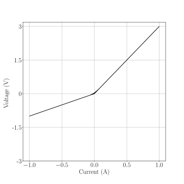
In Fig. 8 we report the curve obtained cycling at a frequency of 50 mHz, which is comparable with the reciprocal of the time constant . We observe that it pinches in the origin, according to (10), and that it is not symmetric around the origin, due to the particular nature of the defining equations.
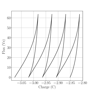
As a result of this lack of symmetry, we do not have a single-valued curve in the plane, and in this case we do not have a complementary asymmetry as the one that exists in the case of the thermistor (Fig. 5), therefore the curve in the plane is not even closed: we show such a curve for 4 periods in Fig. 9. As a consequence, at each cycle there is a net transfer of charge, with a value corresponding to the distance between two consecutive intersections with the horizontal axis.
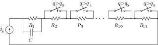
Let us now consider the circuit of Fig. 10, for which we assume charge dependent switches. As a consequence, we have an overall resistance depending on the charge that has flowed through the device. The current source provides the input signal, and is assumed to vary as .
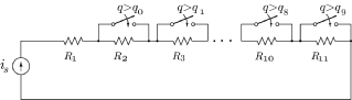
The closing/opening sequences of the 10 switches are as follows: Closing sequence - switch 1 closes once the electrical charge that has flowed through satisfies . The second switch closes when , while the th switch closes when , thus the the th switch closes when . At the end of the positive semi-period, a charge has flowed through , and all the switches are closed.
Opening sequence - this sequence takes place in the negative semi-period, therefore the charge now decreases: the th switch opens when , the th switch opens when , and switch 1 opens when . At the end of this sequence all switches are open and a new cycle can start.
As a first case, we assume that all the resistors are time-independent.
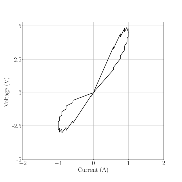
Simulation results are shown in Fig. 11: we notice that the loop is pinched at the origin and is symmetric around the origin. Such a symmetry implies the single-valuedness of the curve, which is reported in Fig. 12. Therefore this simple model is compliant with the original requirement [1] for a memristor, which includes the unambiguous definition through a curve in the plane.


The width of the loop in Fig. 11 depends on the frequency of the current. This is shown in Fig. 13: proceeding clockwise from the top-left subplot we have: Hz, Hz, Hz, and Hz. We clearly observe how the loop area decreases for higher frequencies, for which the charge transfer is smaller, therefore the charge-dependent resistor variation decreases, too. With reference to Fig. 10, this means that a smaller number of switches is operated at higher frequencies.
The corresponding curves are reported in Fig. 14, where they are arranged in a clockwise fashion as in Fig. 13.
In the second case, is instead a resistor whose value has a periodic dependence on time, according to:
| (13) |
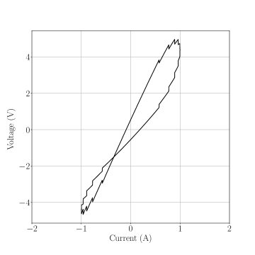
Simulation results are shown in Fig. 15: we can observe that the curve is still pinched at the origin, as a result of the purely resistive nature of the circuit.
In particular the average slope in the first quadrant is larger than that in the third quadrant, as a consequence of the larger value of the resistance during the positive semi-period. In this case the curve is neither single-valued nor closed, because the hysteresis loop is completely asymmetric. We report it in Fig. 16 for two consecutive cycles: after each cycle the charge returns to zero since the driving quantity is a sinusoidal current, while the flux linkage exhibits a net increase at each cycle since the integral of the voltage in the positive semi-period of the current is larger than that in the negative semi-period.
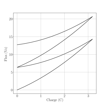
For this circuit, in the high-frequency limit, the hysteresis loop collapses onto two segments, each with a slope equal to the resistance of in the corresponding semi-period (see Fig. 17.)
We point out that both the memristor circuit with time independent resistors and that with a time-dependent resistor satisfy the passivity criterion adopted by Chua [1], i.e., that the instantaneous voltage to current ratio is always positive. This remains true also if the switches are controlled by circuits with active components (such as transistors), because we can assume that the power needed to operate them is obtained from the current flowing through the device. Indeed, this is what happens also in the memristor of [13], where vacancy migration is “powered” by the bias current.
In the last simulation we included a capacitor connected in parallel to , as shown in Fig. 18.
Parameter values, in particular , are chosen in such a way as to clearly show how the presence of a reactive element implies that the curve is not pinched at the origin any longer, and thus the resulting device is neither a memristor nor a memristive system. This is shown in Fig. 19.
IV Conclusion
We have reconsidered the concept of memristor within circuit theory, starting from the definitions of basic circuit elements, in order to understand its actual nature and whether it is truly a fourth basic circuit element.
As a major aspect of our analysis, we have reached the conclusion that the memristor is not a fourth basic circuit element on the same footing as the traditional basic elements, while it can rather be interpreted as an extension of the resistor concept.
In particular, we have shown that, as long as the input and output quantities are a voltage and a current, a memristive system can be seen as a generalized time-variant resistor (generalized in the sense that, with respect to the definition provided by Mauro in 1961, also an additional direct dependence on time is allowed).
We have also stressed the relevant point that the meaningful quantity in the memristor definition is the flux linkage , to be intended as the time integral of the voltage and not as the actual magnetic flux. Without this clarification, ambiguities may appear and conclusions that are not fully sound may be drawn.
Motivated by the presence in the recent memristor literature of references to systems studied in the 50’s and 60’s (such as the thermistor and the giant squid axon), in which an anomalous reactive behavior had been observed, we have revisited the original papers, realizing that such anomalous behavior had been understood and explained at the time with concepts that we can use to provide a general explanation of the nature of the memristor. At the same time we have analyzed the evolution of the definition of the memristor and of the memristive systems, starting from the original 1971 formulation and its 1976 extension.
In particular, we have analyzed the operation of a recently proposed “-memristor,” pointing out that its curve cannot be rigorously pinched in the origin, because coupling with the magnetic flux involves the unavoidable presence of an inductance.
Finally, we have presented a few numerical examples of memristive systems and memristors, showing that, in order to have a single-valued curve in the plane, the curve must possess particular symmetry properties, which are present only in the case of the basic time-invariant memristor as defined by Chua in 1971. Such an essential property is not characteristic of generic memristive systems.
We believe that we have contributed to a clarification of the memristor concept that can be useful for the memristor community, in order to further develop applications and to better focus on new and original problems.
Acknowledgment
M.B. acknowledges financial support from UTA Mayor project No. 8765-17. M.M. acknowledges partial support by the Italian Ministry of Education and Research (MIUR) in the framework of the CrossLab project (Departments of Excellence).
References
- [1] Chua, L.O., Memristor - The Missing Circuit Element,” IEEE Trans. Circuit Theory, vol. CT-18, n. 5, 507-519, 1971.
- [2] Desoer C.A., Kuh, E.S., Basic Circuit Theory, McGraw-Hill Book Company, New York, 1969.
- [3] Chua, L.O., Kang, S.M., Memristive Devices and Systems, Proc. of IEEE, vol. 64, 209-223, 1976.
- [4] M. Di Ventra, Y. V. Pershin, and L. O. Chua, “Circuit elements with memory: memristors, memcapacitors, and meminductors,” Proc. of the IEEE v. 97, 1717-1724, 2009.
- [5] M. Di Ventra, Y. V. Pershin, “On the physical properties of memristive, memcapacitive and meminductive systems,” Nanotechnology 24, 255201, 2013.
- [6] G. Z. Cohen, Y. V. Pershin, and M. Di Ventra, “Lagrange formalism of memory circuit elements: classical and quantum formulations,” Phys. Rev. B v. 85, 165428, 2012.
- [7] Chua L., “Everything you wish to know about memristors but are afraid to ask,” Radioengineering, vol. 24, 319-368, 2015.
- [8] I. Valov, E. Linn, S. Tappertzhofen, S. Schmelzer, J. van der Hurk, F. Lentz, R. Waser, “Nanobatteries in redox-based resistive switches require extension of memristor theory,” Nature Communications v. 4, p. 1771, 2013.
- [9] Corinto, F., Gilli, M., Forti, M., “Flux-Charge Description of Circuits With Non-Volatile Switching Memristor Devices,” IEEE Trans. Circuits Syst. II Express Briefs, vol. 65, no. 5, 642-646, 2018.
- [10] Y.B. Zhao, C.K. Tse, J.C. Feng, and Y.C. Guo, “Application of memristor-based controller for loop filter design in charge-pump phase-locked loops,” Circuits, Syst. Signal Process., vol. 32, no. 3, 1013-1023, 2013.
- [11] R. Tetzlaff, A. Ascoli, I. Messaris, L. O. Chua, “Theoretical Foundations of Memristor Cellular Nonlinear Networks: Memcomputing With Bistable-Like Memristors,” IEEE Trans. Circuits Syst. I: Regular Papers v. 67, 502-515, 2020.
- [12] D. Maldonado, M. B. Gonzalez, F. Campabadal, F. Jimenez-Molinos, M. M. A. Chawa, S. G. Stavrinides, J. B. Roldan, R. Tetzlaff, R. Picos, L. O. Chua, “Experimental evaluation of the dynamic route map in the reset transition of memristive ReRAMs,” Chaos, Solitons and Fractals, v. 139, 110288, 2020.
- [13] Strukov, D.B., Snider, G.S., Stewart D.R. & Williams, R.S., The missing memristor found, Nature, vol. 453, 80-83, 2008.
- [14] Vongehr, S. & Meng, X., The Missing Memristor has Not been Found, Scientific Reports, vol. 5, 1-7, 2015.
- [15] Abraham, I., The case for rejecting the memristor as a fundamental circuit element, Scientific Reports, vol. 8, 10972, 1-9, 2018.
- [16] A. Mauro, “Anomalous Impedance, a Phenomenological Property of Time-variant Resistance: an Analytic Review,” Biophysical Journal vol. 1, p. 353, 1961.
- [17] Adhikari, S.P., Sah, M.Pd., Kim, H. & Chua, L. O., Three Fingerprints of Memristor, IEEE Trans. Circuits and Systems I, vol. 60, 3008-3021, 2013.
- [18] Ascoli, A., Tetzlaff, R. & Menzel, S., “Exploring the Dynamics of Real-World Memristors on the Basis of Circuit Theoretic Model Predictions,” IEEE Circuits and Systems Magazine, 2nd quarter 2018, 48-76, 2018.
- [19] Chua, L.O., Everything You Wish to Know About Memristors But Are Afraid to Ask, Radioengineering, vol. 24, 319-368, 2015.
- [20] K. S. Cole, Membranes, Ions, and Impulses, University of California Press, Berkeley and Los Angeles, 1968.
- [21] H. Cohen, and J. W. Cooley, “The Numerical Solution of the Time-Dependent Nernst-Planck Equations,” Biophysical Journal vol. 5, p. 145-162, 1965.
- [22] L. Chua, V. Sbitnev, and H. Kim, “Hodgkin-Huxley Axon is Made of Memristors,” Int. Journal of Bifurcation and Chaos vol. 22, no. 3, p. 1230011-(1-48), 2012.
- [23] R. Meservey and P. M. Tedrow, “Measurements of the Kinetic Inductance of Superconducting Linear Structures,” J. Appl. Phys. vol. 40, p. 2028, 1969.
- [24] A. L. Hodgkin and A. F. Huxley, “A quantitative description of membrane current and its application to conduction and excitation in nerve,” J. Physiol. vol. 117, p. 500-544, 1952.
- [25] J. M. Tour and T. He, “The fourth element,” Nature vol. 453, p. 42, 2008.
- [26] J. A. Tuszynski, D. Friesen, H. Friedman, V. I. Sbitnev, H. Kim, I. Santelices, A. O. Kalra, S. D. Patel, k. Shankar, L. O. Chua, “Microtubules as Sub-Cellular Memristors,” Scientific Reports v. 10, p. 2108, 2020.
- [27] S. Luryi, “Quantum capacitance devices,” Appl. Phys. Lett vol. 52, p. 501, 1988.
- [28] M. Macucci, K. Hess, G. J. Iafrate, “Electronic energy spectrum and the concept of capacitance in quantum dots,” Phys. Rev. B v. 48, p. 17354 (1993).
- [29] M. Büttiker, “Capacitance, admittance, and rectification properties of small conductors,” J. Phys.: Condens. Matter v. 5, p. 9361 (1993).
- [30] F. Z. Wang, L. Li, L. Shi, H. Wu, and L. O. Chua, “ memristor: Real memristor found,” J. Appl. Phys. vol. 125, 054504, 2019.
- [31] T. L. Gilbert, “A Phenomenological Theory of Damping in Ferromagnetic Materials,” IEEE Trans. Magn. vol. 40, p. 3443, 2004.
- [32] W. Renwick, “A magnetic-core matrix store with direct selection using a magnetic-core switch matrix,” Proceedings of the IEE - Part B Radio and Electronic Engineering vol. 104, p. 436, 1957.
- [33] Chua, L.O., The fourth element, Proceedings of the IEEE, vol. 100, 1920, 2012.
- [34] Chua, L.O., Memristor, Hodgkin-Huxley, and Edge of Chaos, Nanotechnology, 24, 383001, 2013.
- [35] F. Z. Wang, “A Triangular Periodic Table of Elementary Circuit Elements,” IEEE Trans. Circuits Syst. I, Reg. papers v. 60, p. 616, 2013.
- [36] L. Chua, “If it’s pinched it’s a memristor,” Semiconductor Science and Technology v. 29, p. 104001, 2014.
- [37] L. O. Chua, “Reply to comment on ‘If it’s pinched it’s a memristor’,” . Semiconductor Science and Technology v. 34, p. 098002, 2019.
- [38] I. V. Pershin and M. Di Ventra, “Comment on ‘If it’s pinched it’s a memristor’,” . Semiconductor Science and Technology v. 34, p. 098001, 2019.
- [39] F. Caravelli, G.-W. Chern, C. Nisoli, “Artificial Spin Ice Phase-Change Memory Resistors,” arxiv:1908.08073v1, 2019.