Investigation of the orientation relationship between nano-sized G-phase precipitates and austenite with scanning nano-beam electron diffraction using a pixelated detector
Abstract
Scanning nano-beam electron diffraction with a pixelated detector was employed to investigate the orientation relationship of nanometer sized, irradiation induced G-phase (M6Ni16Si7) precipitates in an austenite matrix. Using this detector, the faint diffraction spots originating from the small G-phase particles could be resolved simultaneously as the intense matrix reflections. The diffraction patterns were analyzed using a two-stage template matching scheme, whereby the matrix is indexed first and the precipitates are indexed second after subtraction of the matrix contribution to the diffraction patterns. The results show that G-phase forms with orientation relationships relative to austenite that are characteristic of face-centered cubic (FCC) to body-centered cubic (BCC) transformations. This work demonstrates that nano-beam electron diffraction with a pixelated detector is a promising technique to investigate orientation relationships of nano-sized precipitates with complex crystal structures in other material systems with relative ease.
keywords:
austenitic steels , precipitation , transition metal silicides , scanning/transmission electron microscopy , irradiationG-phase is an intermetallic silicide with a complex cubic crystal structure (space group Fmm, lattice parameter around 1.1 nm) [1] and a stoichiometry represented by the formula M6X16Si7 with M and X representing multiple possible metals. G-phase can be precipitated in various steels, with M=Ti, Mn, Cr and X=Ni, Fe being the most common varieties. In duplex steels subjected to ageing heat treatment, the phase precipitates in the ferrite phase with the cube-on-cube orientation relationship [2, 3, 4]. Large G-phase domains on grain boundaries are associated with embrittlement [5, 6], but precipitation of G-phase on dislocations can improve strength and creep resistance [7]. Hence G-phase is of high technological importance in ferritic and duplex stainless steels.
In austenitic stainless steels, G-phase (M6Ni16Si7) does not form under any ageing conditions, but it readily forms under irradiation over a wide temperature range (300–700∘C) [8, 9, 10]. This is detrimental in nuclear applications, where the formation of G-phase in austenitic steels is associated with void swelling [9, 11, 12, 13, 14], which leads to unacceptable embrittlement and loss of strength [15]. G-phase grows in austenitic steel due to radiation induced segregation of Ni and Si [16]. However, the nucleation mechanism of G-phase from Ni-Si supersaturated regions is not well understood. Moreover, the orientation relationship of the phase in austenite has not been established but is critical for understanding its detrimental effects. The orientation relationship and particle morphology are prerequisite to determining the precipitate/matrix interfacial structure, which is ultimately responsible for the interaction with irradiation-induced point defects.
The cube-on-cube orientation relationship [17] has been proposed to exist between G-phase and austenite, but most authors report there is no preferential orientation relationship [8, 16]. Recent electron diffraction work has shown irradiation induced G-phase may have a preferential but complicated orientation relationship with austenite [18, 19]; the Kurdjumov-Sachs (KS) orientation relationship (, ) was suggested. Orientation relationships with many variants like KS, Nishiyama-Wassermann (, ), Pitsch (, ) or Bain (, ) are typically associated with the transformation of face-centered cubic (FCC) austenite () to body-centered cubic (BCC) ferrite or martensite (). Since G-phase forms with the cube-on-cube orientation relationship in ferrite, it is plausible to assume that G-phase may form in austenite analogously to ferrite [3].
The difficulty in establishing the orientation relationship of nano-sized precipitates with complex crystal structures using classical methods like selected area electron diffraction (SAED) is that diffraction patterns tend to contain many closely spaced reflections from multiple particles. If the orientation relationships are non-trivial with multiple variants, indexing these patterns is extremely challenging, and it is impossible to tilt individual particles to different zone axis orientations. An additional layer of complexity in this specific case is that irradiated austenite typically contains other precipitated phases with complex crystal structures and similar lattice parameter as G-phase, such as M23C6; these phases are often confused or misidentified.
In this paper, we attempted to elucidate the orientation relationship of nano-sized (10–20 nm) G-phase precipitates in ion-irradiated austenite using scanning nano-beam electron diffraction (NBED) inside a transmission electron microscope (TEM) utilizing a fast pixelated electron detector. Scanning nano-beam diffraction is a technique whereby an electron probe with small convergence angle (typically mrad) is scanned across the sample, and a diffraction pattern is collected at each scan position. If the distance between the particles is large relative to the thickness of the specimen, then diffraction patterns will contain signal from individual particles and the matrix only. By comparing the diffraction patterns to a library of simulated diffraction patterns of the crystal in different orientations (templates), local orientations in each scan position can be derived [20, 21]. The advantages of this technique are that no specific sample orientation is required before data collection, and crystallographic information from diffraction patterns can be directly correlated to real space coordinates.
One challenge of this method is that diffraction patterns contain both (weak) signal from the small precipitates and (strong) signal from the matrix phase above and below the particles. Since some matrix reflections can correspond to some precipitate reflections and since they tend to be more intense than the precipitate reflections, this can confuse the template matching algorithm. Recently it was demonstrated that this problem can be overcome by using a two stage indexation method [22, 23]. In this method, the patterns are first indexed with the matrix templates, masked with the matrix template solution, and subsequently indexed with the precipitate phase templates. Our initial trials showed that the conventional method of NBED data collection utilizing the ASTAR system (NanoMegas) was insufficiently sensitive to detect the faint G-phase reflections. Reliable indexing of the diffraction patterns of small precipitates with complex crystal structure requires electron detection with the highest possible resolution and dynamic range. Hence, diffraction pattern data was collected with the fast (up to 384 frames/s) TemCAM-XF416 pixelated CMOS detector (TVIPS). A comparison of data collected with the ASTAR and TVIPS systems is given in supplementary materials. The microscope used was a JEOL 2200FS TEM, equipped with a Schottky field emission gun and operating at 200 kV. In addition to NBED, the morphology of the precipitates was investigated using high resolution high angle annular dark field (HR-HAADF) scanning TEM (STEM) using a probe corrected Titan microscope (Thermo Fisher Scientific) operating at 300 kV.
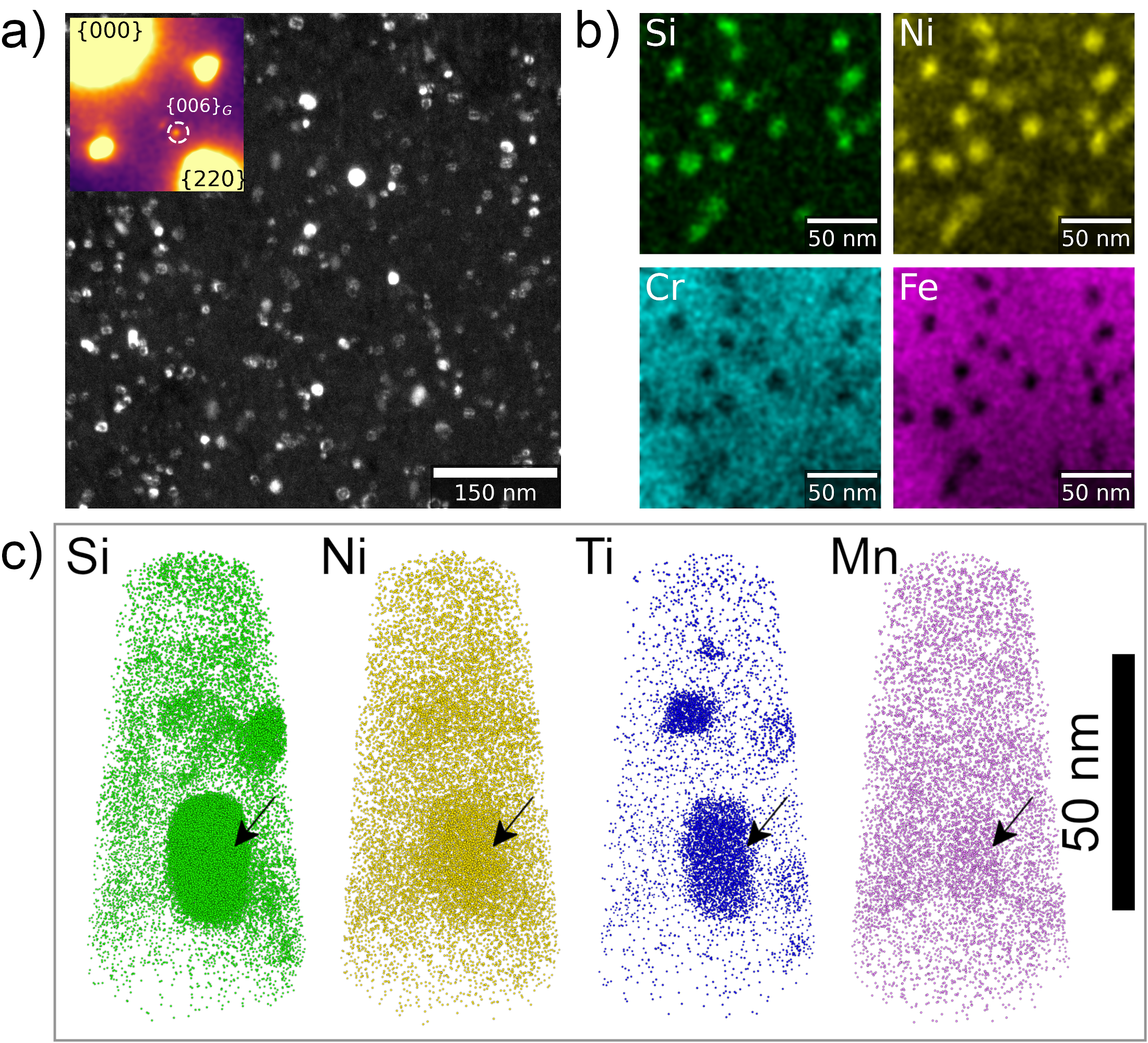
The material used in the study was an austenitic stainless steel in the 15–15Ti family with composition 15 wt% Ni, 15 wt% Cr, 1.8 wt% Mn, 1.2 wt% Mo, 0.5 wt% Ti, 0.6 wt% Si, 0.1 wt% C, bal. Fe [24], with a grain size of 10–15 m. The material was irradiated with 4.5 MeV Fe2+ ions up to 40 dpa at 600 ∘C. Additional details about the material and its characterization were published elsewhere [25, 26, 27]. Figure 1 shows the G-phase precipitates as imaged in a) TEM dark field (DF), b) using scanning TEM (STEM) energy dispersive X-ray spectroscopy (EDX), and c) atom probe tomography (APT). The precipitates were 10–20 nm in diameter, enriched in Si, Ni, Ti and Mn, and depleted in all other alloying elements. No other irradiation induced phases were found in this steel, making this material ideally suited to study G-phase. Electron transparent samples for TEM investigations were prepared via focused ion beam cross-section lift-out in a SCIOS 2 HiVac (Thermo Fisher Scientific) using a final cleaning at 2 kV.
The NBED data was collected using a camera length of 80 cm and a convergence angle of approximately 0.5 mrad. A map of scan positions was collected with a step size between 1-2 nm. The region of interest was tilted slightly away from a zone axis so that only few matrix reflections would be strongly excited. The raw data from the camera was converted to the .BLO file format compatible with the ASTAR software (NanoMegas) using a custom tool [28] and analyzed with methods and tools described in refs. [22, 23]. This conversion involves some information loss, since the TVIPS camera collects images at 16-bit pixel depth, but the BLO format only supports 8-bit images.
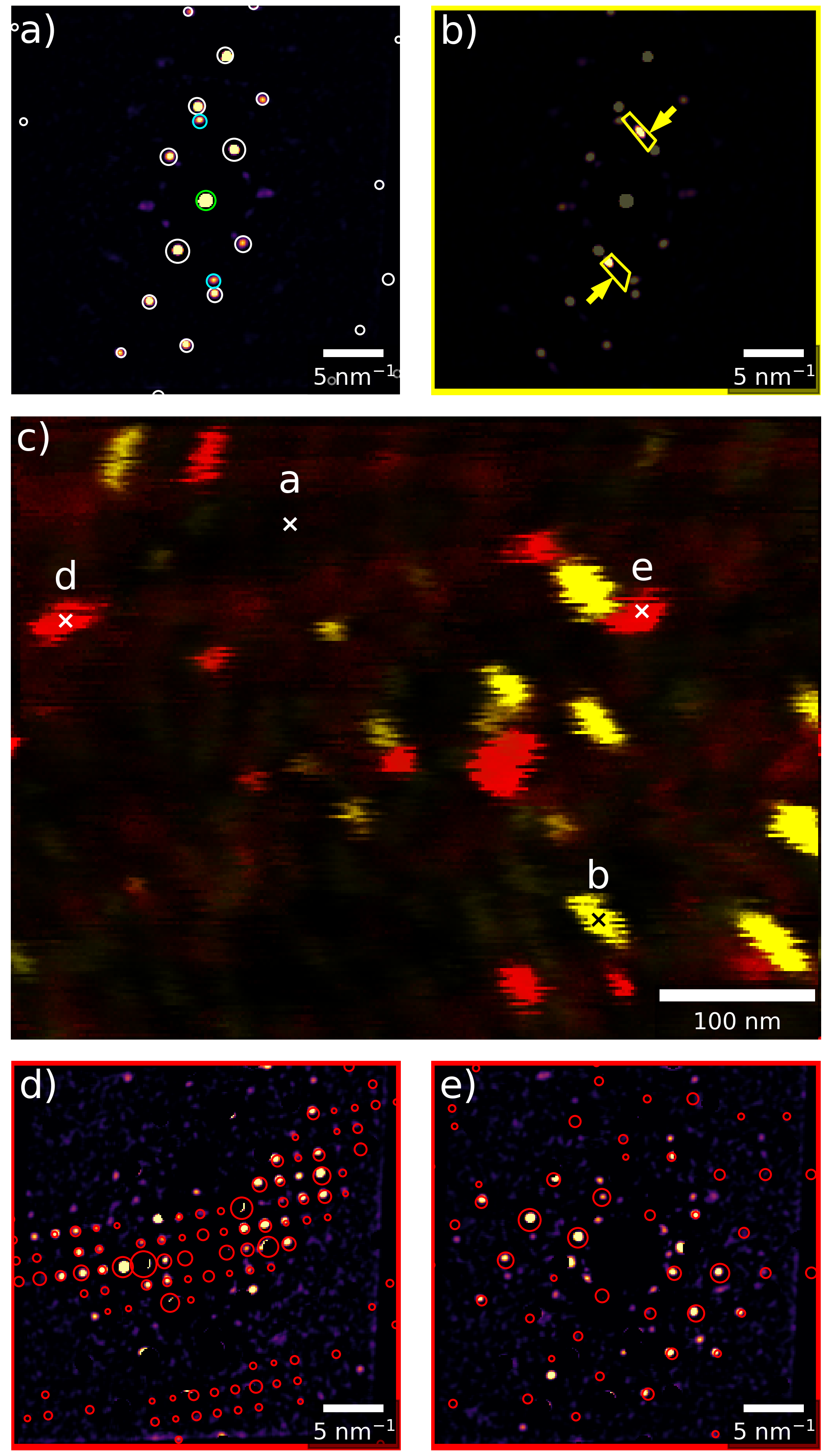
The two stage process for indexing the G-phase is illustrated in Figure 2 (prepared with Hyperspy [29, 30] and Pyxem [31]). First, the austenite matrix is indexed in each pattern. Figure 2 a) shows a diffraction pattern from the matrix and the best fit austenite template as white circles. The direct beam is circled with green. Two additional diffraction spots were detected near the {220} reflections and circled with cyan. These were found in all diffraction patterns and did not correspond to any distinguishable features in DF images; possibly they originate from surface oxide or small scale point defect clusters. After the first step, the matrix contribution is removed with a mask created from the best fit template. Signal that remains in the diffraction patterns originates from the G-phase particles and Frank loop defects (which also form under irradiation). The Frank loops can be isolated by masking everything except the strip between the {220} and {111} matrix reflections as shown in Figure 2 b). The virtual dark field image (VDF) from the Frank loops is shown in yellow in Figure 2 c); since they grow on {111} planes they are elongated perpendicular to this direction. A dark field TEM image demonstrating the presence of Frank loops in the irradiated layer can be found in supplementary materials. Finally in the second stage, the G-phase is indexed. The G-phase VDF is shown in red in Figure 2 c). Two patterns from G-phase particles with the matrix contribution subtracted are shown in Figure 2 d) and e). The best fit (highest matching index) G-phase templates are superimposed on the images. Note that all features in the VDF image show jerky distortions in the x direction due to scan noise in the scanning system at high magnification, but since each diffraction pattern image is independent this does not impact the indexing process.
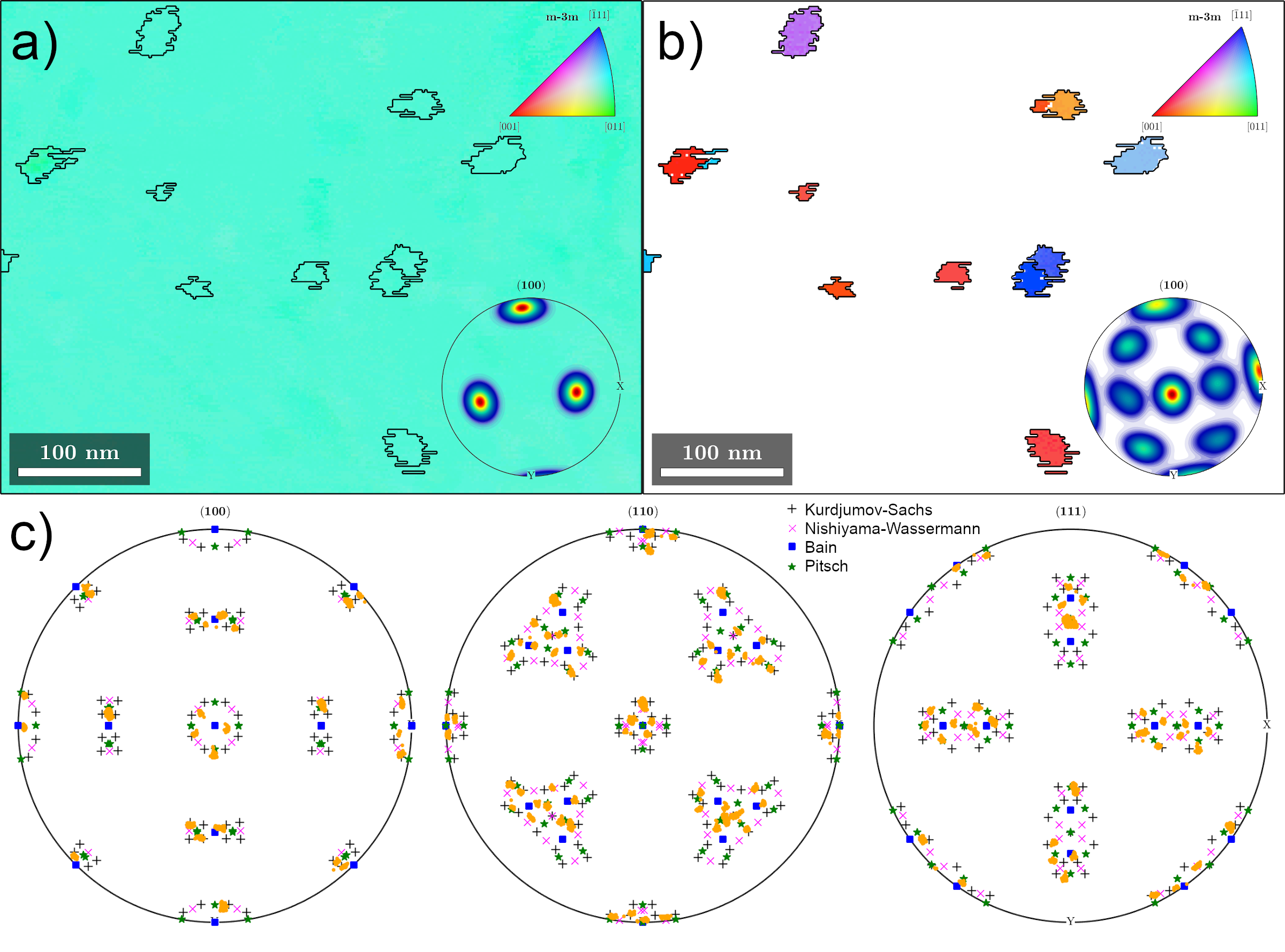
The orientation maps were processed with MTEX v5.4.0 [32]. Figure 3 summarizes the orientation results derived from the template matching procedure. Figure 3 a) shows the austenite inverse pole figure (IPF) map and in the bottom-right corner the (100) pole figure; both confirm that the matrix was oriented a few degrees away from a zone axis. The outlines of detected G-phase particles are superimposed on the plot. The misorientation within the austenite grain spanned a range of about relative to the mean orientation. Figure 3 b) shows a filtered G-phase inverse pole figure map and the (100) pole figure in the bottom right corner. Pixels with a low correlation match index were excluded. The map corresponds closely to the red features in the VDF image in Figure 2 c). The data shows that some particles are oriented closely to a zone, while others are oriented close to a zone. From the pole figure it appears that some directions of the G-phase align closely with the directions of the matrix as well as the directions. Figure 3 c) represents the relative orientation between the G-phase and the matrix in each pixel. The pole figures should be interpreted as if material in each pixel were rotated such that the austenite is aligned with the image coordinate system. Each orange dot represents a G-phase pole from an indexed pixel; individual particles are thus represented by small orange point clouds. Also shown on the plot for comparison are all the variants of the most common idealized orientation relationships between FCC and BCC phases. These poles are to be interpreted as the BCC poles if the FCC basis were aligned with the coordinate system of the plot. The experimental data points all fall within the range of these ideal orientation relationships, which clearly demonstrates that G-phase forms with orientation relationships characteristic of the FCC to BCC transformation.
Hence, the results suggest there is an analogy between the way G-phase forms in austenite and the way ferrite or martensite do. Despite the space groups of G-phase and austenite being the same (Fmm), the G-phase lattice most closely resembles a superstructure of ferrite; only minor atomic shuffles are required to transform a supercell of BCC ferrite into the G-phase unit cell [3]. If the G-phase structure is similar to a BCC supercell, this implies the formation of the phase must be associated with a similar kind of tetragonal distortion and rotation of the FCC lattice as when austenite transforms to ferrite, which explains the similarity between the orientation relationships. For all but the smallest particles, these strains must be accommodated by interface dislocations or twinning in the precipitating phase, which to a large extent determine the precipitate morphology and habit plane [33, 34].
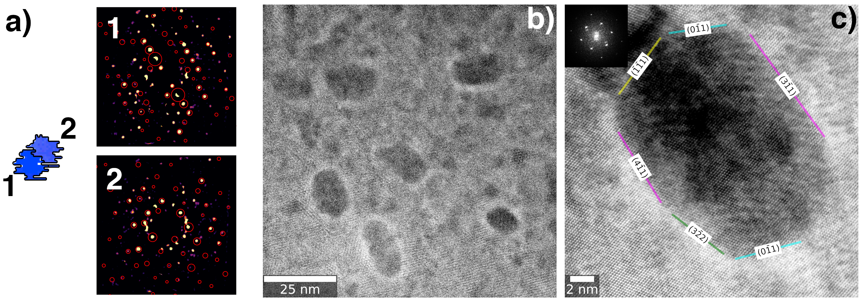
Some evidence of twinning inside G-phase precipitates was found, one example shown in Figure 4 a). The two parts of the particle deviate 52∘ over a tilt axis close to the direction (nearly parallel to the optical axis) which resembles a twin of a 60∘ tilt over a tilt axis. The grains also appear to be joined on a plane parallel to {111}γ since the interface is parallel to the edge-on Frank loops in Figure 2. The deviation from the ideal twin rotation likely originates from a cumulation of errors in the indexing procedure; this could be the result of the relative weakness of the G-phase reflections, high concentration of defects and localized strains, the substantial image processing (including masking) prior to indexing the G-phase, and dynamic diffraction effects that are not accounted for in the template matching procedure.
It may be possible to further improve the angular resolution by optimizing the template matching routine to use mainly distant reflections, which are more sensitive to small changes in orientation [35]. This could be coupled with more advanced acquisition strategies, such as acquiring multiple maps at different camera lengths optimized for each phase. In the dataset described here, the camera length is large for the matrix phase resulting in few matrix reflections in each pattern; this may increase uncertainty in determining the matrix orientation. Furthermore, a more quantitative estimate of the angular resolution might be obtained via automated parameter studies; an enabling solution is being developed within the Pyxem library [31].
FCC to BCC transformations tend to be associated with irrational interface planes containing an invariant line along an irrational lattice vector which can be predicted from lattice parameter ratios [33]. If it is assumed that the G-phase unit cell represents BCC unit cells and the ratio , plate-shaped morphologies with near KS relationship and an invariant line close to in the FCC lattice (or in the BCC lattice) are expected. Precipitates imaged with STEM-HAADF tended to be nearly round or slightly elongated in projection as shown in Figure 4 b), which is consistent with a plate-shaped morphology. A higher magnification image of one particle is shown in Figure 4 c). The projected interface is demarcated by colored lines and labeled with Miller indices of the projected planes with respect to the austenite lattice. The particles do not show clearly resolved low index facets, which is consistent with the theory of an irrational habit plane containing an invariant line. The shape of the particle in Figure 4 c) would be consistent with a plate-shaped particle with invariant line close to and habit plane between and , inclined at an angle of approximately with the viewing direction. In this scenario, a circular platelet would have an aspect ratio of 0.86, which is quite close to the observed value of 0.7 in the particle. Unambiguous identification of the habit plane and the invariant line from the projections in these images may not be possible, but the findings seem consistent with theory [33] and observations in other FCC-BCC systems [34]. A more precise confirmation of the orientation relationship of G-phase would require very thin regions (where the precipitate and matrix do not overlap) to be investigated along a zone axis with HR-(S)TEM – approximately 1/4 of the particles should be oriented along a zone if the particles follow near NW or KS relationships.
In summary, nano-sized irradiation induced G-phase precipitates were found to follow orientation relationships in austenite characteristic of the FCC to BCC transformation through NBED using a pixelated detector. Only by collecting the data using a CMOS camera with high signal-to-noise and high dynamic range could the faint G-phase reflections be adequately resolved to index them with the template matching procedure. If invariant line theory can be extended to this system, the KS orientation relationship should be preferred and the precipitates should have a plate-like morphology, which was confirmed by HR-HAADF imaging. This information could be supplied to density functional theory or molecular dynamics simulations to investigate the energies and the interaction with radiation induced point defects of the precipitate/matrix interfaces, which might ultimately explain the relationship between this phase, void swelling and property degradation. In the future, resolving individual orientation relationship variants directly with 4D-STEM may be enabled with finetuning the template matching procedure and data acquisition strategies. This case study also shows the promise of this technique for investigating complex nano-sized precipitates in other material systems, for example in magnesium, aluminium, or titanium alloys [36, 37, 38]. Investigating the early stages of precipitation or quantifying orientation relationship variants once they can be resolved may be interesting application domains.
Acknowledgements
We acknowledge funding through BiGmax (https://www.bigmax.mpg.de/), the Max Planck research network on big-data driven materials science. This work was in part supported by the U.S. Department of Energy, Office of Nuclear Energy under DOE Idaho Operations Office Contract DE-AC07-051D14517 as part of a Nuclear Science User Facilities experiment. We want to acknowledge SCK-CEN and the MYRRHA project for supplying the material, the staff at MIBL for assisting with the ion irradiations, and Dr. X. Zhou for the valuable discussion.
References
- Yan et al. [2009] X. Yan, A. Grytsiv, P. Rogl, V. Pomjakushin, X. Xue, Journal of alloys and compounds 469 (2009) 152–155.
- Auger et al. [1990] P. Auger, F. Danoix, A. Menand, S. Bonnet, J. Bourgoin, M. Guttmann, Materials Science and Technology 6 (1990) 301–313.
- Mateo et al. [1997] A. Mateo, L. Llanes, M. Anglada, A. Redjaimia, G. Metauer, Journal of Materials Science 32 (1997) 4533–4540.
- Spiegel [1963] F. Spiegel, Trans. Met. Soc. AIME 27 (1963) 575.
- Shuro et al. [2012] I. Shuro, H. Kuo, T. Sasaki, K. Hono, Y. Todaka, M. Umemoto, Materials Science and Engineering A 552 (2012) 194–198. doi:10.1016/j.msea.2012.05.030.
- Shiao et al. [1994] J. Shiao, C. Tsai, J. Kai, J. Huang, Journal of Nuclear Materials 217 (1994) 269–278.
- Sun et al. [2017] W. Sun, R. Marceau, M. Styles, D. Barbier, C. Hutchinson, Acta Materialia 130 (2017) 28–46.
- Lee et al. [1980] E. Lee, P. Maziasz, A. Rowcliffe, The Structure and Composition of Phases Occurring in Austenitic Stainless Steels in Thermal and Irradiation Environments, Technical Report, Oak Ridge National Lab., 1980. URL: https://www.osti.gov/biblio/5889791.
- Boothby and Williams [1988] R. M. Boothby, T. M. Williams, Journal of Nuclear Materials 152 (1988) 123–138.
- Lee et al. [1983] E. H. Lee, N. H. Packan, L. K. Mansur, Journal of Nuclear Materials 117 (1983) 123–133. doi:10.1016/0022-3115(83)90018-1.
- Cawthorne and Fulton [1967] C. Cawthorne, E. J. Fulton, Nature 216 (1967) 575–576. doi:10.1038/216575a0.
- Russell [1978] K. Russell, Acta Metallurgica 26 (1978) 1615–1630. doi:10.1016/0001-6160(78)90071-8.
- Mansur [1978] L. Mansur, Nuclear Technology 40 (1978) 5–34. doi:10.13182/NT78-2.
- Lee and Mansur [1992] E. Lee, L. Mansur, Metallurgical Transactions A 23 (1992) 1977–1986. doi:10.1007/BF02647545.
- Garner [2012] F. Garner, in: R. Konings (Ed.), Comprehensive Nuclear Materials, Elsevier, New York, 2012, pp. 1–63.
- Maziasz [1989] P. J. Maziasz, Journal of Nuclear Materials 169 (1989) 95–115. doi:10.1016/0022-3115(89)90525-4.
- Williams et al. [1979] T. Williams, J. Titchmarsh, D. Arkell, Journal of Nuclear Materials 82 (1979) 199 – 201. doi:10.1016/0022-3115(79)90055-2.
- Renault-Laborne et al. [2016] A. Renault-Laborne, J. Garnier, J. Malaplate, P. Gavoille, F. Sefta, B. Tanguy, Journal of Nuclear Materials 475 (2016) 209–226. doi:10.1016/j.jnucmat.2016.04.020.
- Renault-Laborne et al. [2014] A. Renault-Laborne, J. Malaplate, C. Pokor, B. Tanguy, Effects of Radiation on Nuclear Materials (2014) 1–24. doi:10.1520/stp157220130096.
- Rauch et al. [2008] E. Rauch, M. Véron, J. Portillo, D. Bultreys, Y. Maniette, S. Nicolopoulos, Microscopy and Analysis 22 (2008) S5–S8.
- Rauch et al. [2010] E. F. Rauch, J. Portillo, S. Nicolopoulos, D. Bultreys, S. Rouvimov, P. Moeck, Zeitschrift fur Kristallographie 225 (2010) 103–109. doi:10.1524/zkri.2010.1205.
- Valery et al. [2017] A. Valery, E. F. Rauch, L. Clément, F. Lorut, Journal of Microscopy 268 (2017) 208–218. doi:10.1111/jmi.12599.
- Rauch and Véron [2019] E. Rauch, M. Véron, Microscopy and Microanalysis 25 (2019) 1922–1923. doi:10.1017/s1431927619010341.
- Delville et al. [2014] R. Delville, E. Stergar, M. Verwerft, in: 22nd International Conference on Nuclear Engineering ICONE22, ASME, Prague, Czech Republic, 2014.
- Cautaerts et al. [2018a] N. Cautaerts, R. Delville, E. Stergar, D. Schryvers, M. Verwerft, Journal of Nuclear Materials 507 (2018a) 177–187. doi:10.1016/j.jnucmat.2018.04.041.
- Cautaerts et al. [2018b] N. Cautaerts, R. Delville, E. Stergar, D. Schryvers, M. Verwerft, Acta Materialia 164 (2018b) 90–98. doi:10.1016/J.ACTAMAT.2018.10.018.
- Cautaerts et al. [2020] N. Cautaerts, R. Delville, E. Stergar, J. Pakarinen, M. Verwerft, Y. Yang, C. Hofer, R. Schnitzer, S. Lamm, P. Felfer, D. Schryvers, Acta Materialia 197 (2020) 184–197. doi:10.1016/j.actamat.2020.07.022.
- Cautaerts and Harrison [2020] N. Cautaerts, P. Harrison, din14970/tvipsconverter: tvipsconverter v0.1.3, 2020. doi:10.5281/zenodo.4288857.
- de la Peña et al. [2020] F. de la Peña, E. Prestat, V. T. Fauske, P. Burdet, T. Furnival, P. Jokubauskas, M. Nord, T. Ostasevicius, K. E. MacArthur, D. N. Johnstone, M. Sarahan, J. Lähnemann, J. Taillon, pquinn dls, T. Aarholt, V. Migunov, A. Eljarrat, J. Caron, S. Mazzucco, B. Martineau, S. Somnath, T. Poon, M. Walls, T. Slater, N. Tappy, N. Cautaerts, F. Winkler, G. Donval, J. C. Myers, hyperspy/hyperspy: Release v1.6.1, 2020. doi:10.5281/zenodo.4294676.
- de la Peña et al. [2017] F. de la Peña, T. Ostasevicius, V. T. Fauske, P. Burdet, P. Jokubauskas, M. Nord, M. Sarahan, E. Prestat, D. N. Johnstone, J. Taillon, et al., Microscopy and Microanalysis 23 (2017) 214–215.
- Johnstone et al. [2021] D. N. Johnstone, P. Crout, M. Nord, J. Laulainen, S. Høgås, E. Opheim, B. Martineau, C. Francis, T. Bergh, E. Prestat, S. Smeets, A. Ross, S. Collins, I. Hjorth, Mohsen, T. Furnival, D. Jannis, N. Cautaerts, E. Jacobsen, A. Herzing, T. Poon, H. W. Ånes, J. Morzy, T. Doherty, A. Iqbal, T. Ostasevicius, M. von Lany, R. Tovey, pyxem/pyxem: pyxem 0.13.0, 2021. doi:10.5281/zenodo.4436723.
- Bachmann et al. [2010] F. Bachmann, R. Hielscher, H. Schaeben, Solid State Phenomena 160 (2010) 63–68. doi:10.4028/www.scientific.net/SSP.160.63.
- Dahmen [1982] U. Dahmen, Acta Metallurgica 30 (1982) 63–73.
- Weatherly and Zhang [1994] G. C. Weatherly, W. Z. Zhang, Metallurgical and Materials Transactions A 25 (1994) 1865–1874. doi:10.1007/BF02649034.
- Jeong et al. [2021] J. Jeong, N. Cautaerts, G. Dehm, C. H. Liebscher, arXiv preprint arXiv:2102.09711 (2021).
- Nie [2012] J.-F. Nie, Metallurgical and Materials Transactions A 43 (2012) 3891–3939.
- Ma et al. [2021] K. Ma, Y. Zheng, S. Dasari, D. Zhang, H. L. Fraser, R. Banerjee, MRS Bulletin (2021) 1–8.
- Lendvai [1996] J. Lendvai, in: Materials Science Forum, volume 217, Trans Tech Publ, pp. 43–56.