Crossover between short and long range proximity effects in SFS junctions with Ni-based ferromagnets.
Abstract
We study Superconductor/Ferromagnet/Superconductor junctions with CuNi, PtNi, or Ni interlayers. Remarkably, we observe that supercurrents through Ni can be significantly larger than through diluted alloys. The phenomenon is attributed to the dirtiness of disordered alloys leading to a short coherence length despite a small exchange energy. To the contrary, pure Ni is clean resulting in a coherence length as long as in a normal metal. Analysis of temperature dependencies of critical currents reveals a crossover from short (dirty) to long (clean) range proximity effects in Pt1-xNix with increasing Ni concentration. Our results point out that structural properties of a ferromagnet play a crucial role for the proximity effect and indicate that conventional strong-but-clean ferromagnets can be advantageously used in superconducting spintronic devices.
I I. Introduction
A competition between superconductivity and ferromagnetism leads to an unconventional proximity effect, studied both theoretically Beenakker_1995 ; Demler_1997 ; Kadigrobov_2001 ; Tagirov_2003 ; Eschrig_2004 ; Buzdin2005 ; Efetov2005 ; Radovic_2005 ; Golubov ; Silaev_2009 ; Fominov ; Buzdin_2010 ; Aladoust_2010 ; Pugach_2011 ; Melnikov_2012 ; Linder_2015 ; Silaev_2017 ; Klenov_2019 and experimentally Petrashov_1999 ; Ryazanov_2001 ; Chandrasekhar_2001 ; Kontos_2002 ; Oboznov_2006 ; Born_2006 ; Keizer_2006 ; Robinson_2007 ; Bannykh_2009 ; Robinson_2010 ; Aarts_2010 ; Wang_2010 ; Birge_2011 ; Bolginov_2012 ; Golod_2013a ; Dresselhaus_2014 ; Kompaniits_2014 ; Iovan_2014 ; Sidorenko_2016 ; Aarts_2017 ; Birge_2018 ; Skryabina_2019 ; Kapran_2020 . In strong ferromagnets (F) Fe, Co, Ni, exchange energies, K, are much larger than the energy gap, K, in low- superconductors (S). Therefore, spin-singlet Cooper pairs are usually broken at a very short range nm in F, as shown by many experimental works Chandrasekhar_2001 ; Robinson_2007 ; Bannykh_2009 ; Robinson_2010 ; Birge_2011 ; Dresselhaus_2014 ; Birge_2018 ; Skryabina_2019 . There are, however, reports about a long range proximity effect (LRPE) (tens to hundreds of nm) Petrashov_1999 ; Keizer_2006 ; Wang_2010 ; Golod_2013a ; Kompaniits_2014 , which is often ascribed to the spin-triplet order parameter that should be immune to the ferromagnetic order.
Interpretation of LRPE remains controversial. First, there is a seeming irreproducibility of experimental results, cf. Refs. Petrashov_1999 ; Wang_2010 ; Kompaniits_2014 and Chandrasekhar_2001 ; Skryabina_2019 . Second, the triplet order should appear only in the noncollinear magnetic state Buzdin2005 ; Efetov2005 ; Fominov , the origin of which is often unclear for structures containing only one F layer. Although several subtle effects, such as quantum fluctuations Kadigrobov_2001 , active interfaces Eschrig_2004 , domains Robinson_2010 ; Aarts_2017 , inhomogeneities Silaev_2009 ; Aladoust_2010 ; Silaev_2017 and spin-orbit coupling Linder_2015 ; Silaev_2017 were suggested, they are difficult to confirm or control in experiment. Finally, the proximity effect depends on the electronic mean-free path (m.f.p.), , and, thus, on the internal structure. In particular, it has been predicted, that in clean F even a singlet supercurrent should exhibit LRPE Demler_1997 ; Radovic_2005 ; Buzdin_2010 ; Pugach_2011 ; Melnikov_2012 ; Born_2006 . Experimental analysis of SFFS spin-valves has shown that the singlet current is dominant for diluted F Iovan_2014 and remain considerable even for pure Ni Kapran_2020 . Clarification of LRPE mechanisms and the ways of controlling supercurrents in S/F heterostructures is important both for fundamental understanding of unconventional superconductivity Balatsky_2019 , and for application in superconducting spintronics Bolginov_2012 ; Dresselhaus_2014 ; Birge_2018 ; Klenov_2019 ; Kapran_2020 .

Here we study nanoscale SFS Josephson junctions (JJ’s) containing either diluted Ni-alloys Cu1-xNix and Pt1-xNix, Cu/Ni bilayer or pure Ni. Counterintuitively, we observe that the supercurrent density, , through Ni can be much larger than through diluted alloys with the same thickness. Using in-situ absolute Josephson fluxometry (AJF), we demonstrate that Ni interlayers in our junctions exhibit full saturation magnetization as in bulk Ni, which precludes presence of extended dead magnetic layers. The clue to understanding of our results is obtained from the analysis of evolution of temperature dependencies, , in Nb/Pt1-xNix/Nb JJ’s with increasing Ni concentration. It shows that in diluted Ni-alloys, , the proximity effect is short range, despite a small , due to an extremely short m.f.p. is such atomically disordered alloys. To the contrary, pure Ni remains clean, facilitating ballistic Cooper pair transport and LRPE similar in scale to that in the normal metal Pt. Our results demonstrate that the proximity effect in ferromagnets depends not only on composition and , but also essentially on the internal structure. This may help to resolve some of the controversies around LRPE. We conclude that strong-but-clean ferromagnets may have advantages compared to weak-but-dirty for device applications.
The paper is organized as follows. In sec. II we describe sample fabrication and experimental procedures. In sec. III we discuss main experimental results, including III A. in-situ magnetic characterization of Ni interlayers via AJF and III B. analysis of temperature dependencies of critical currents, which reveals a crossover between clean (ballistic) and dirty (diffusive) transport. In the Appendix we provide additional information about A. film structure, B. junction characteristics, C. properties of Nb/Pt1-xNix/Nb junctions, D. interface resistances in Nb/Pt1-xNix/Nb junctions, and E. extraction of magnetization curves from AJF analysis.
II II. Samples and Experimental
We present data for nano-scale SFS junctions with F-interlayers made of Cu0.4Ni0.6 and Pt1-xNix alloys with , pure Ni and a Cu/Ni (N/F, N-normal metal) bilayer. SFS multilayers were deposited by dc-magnetron sputtering in a single cycle without breaking vacuum. Cu1-xNix films were deposited by cosputtering from Cu and Ni targets and the concentration was controlled by the corresponding sputtering rates. Pt1-xNix films were deposited from composite targets with different areas of Ni and Pt segments and Ni concentration was estimated using energy-dispersive X-ray spectroscopy. More details about fabrication and magnetic properties of Pt1-xNix films can be found in Refs. Golod_2011 ; Golod_2013b and in Appendices C and D. Nb/Ni/Nb JJ’s with different were fabricated from the same wafer with a calibrated Ni-thickness gradient Born_2006 . Nb(S) electrodes were nm thick. Multilayers were first patterned by photolithography and reactive ion etching and then processed by focused ion beam (FIB). Nano-scale JJ’s with sizes down to nm were made by FIB-nanosculpturing Robinson_2007 ; Golod_2010 ; Iovan_2014 . Small sizes are necessary both for achieving the monodomain state Iovan_2017 ; Kapran_2020 and for enhancing normal resistances to comfortably measurable values, . We present data for JJ’s with different sizes, interlayer thicknesses, , and compositions. Junction parameters are listed in Tables I-III of the Appendix. Properties of Josephson spin valves with similar CuNi and Ni interlayers can be found in Refs. Iovan_2014 and Kapran_2020 . Figure 1 shows (a) a scanning electron microscope (SEM) image of one of the studied Nb/Ni/Nb JJ’s and (b) a sketch with a current path.
Measurements are performed in 3He and 4He closed-cycle cryostats. Magnetic field, parallel to the junction plane, is supplied by a superconducting solenoid. We will show measurements with field oriented either parallel (easy axis), or perpendicular (hard axis) to the long side of the JJ.
III III. Results and discussion
Figs. 1 (c,d) show Current-Voltage characteristics (-) at zero field for (c) Nb/Cu0.4Ni0.6/Nb junction with nm at K and (d) Nb/Ni/Nb junction with nm at different temperatures, K. The shapes of -’s are typical for proximity-coupled JJ’s, described by the resistively shunted junction model.
Figs. 1 (e,f) show temperature dependencies of critical current densities for (e) the same Nb/Cu0.4Ni0.6/Nb JJ, and (f) Nb/Ni/Nb JJ’s with 5, 7, 10 and 20 nm. It is seen that the JJ with a diluted Cu0.4Ni0.6 interlayer has a significantly smaller than the JJ with pure Ni with the same nm, compare red lines in Figs. 1 (e) and (f). It is also seen that the Cu0.4Ni0.6 JJ exhibits stronger superlinear temperature dependence with a positive curvature at elevated , which is well described by the power-law dependence with . On the other hand, Ni JJ’s show almost linear , irrespective of Ni thickness, albeit with a varying onset temperature .
III.1 III A. In-situ magnetic characterization of Ni interlayers via absolute Josephson fluxometry.
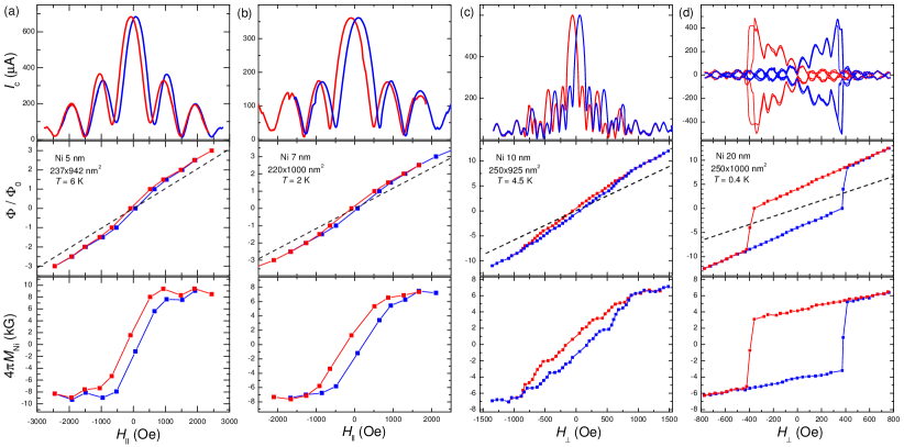
Top panels in Figure 2 represent measured modulation patterns for Nb/Ni/Nb JJ’s with different (a) 5 nm, (b) 7 nm, (c) 10 nm and (d) 20 nm. Junction sizes and measurement temperatures are indicated in the Figure. Modulation patterns are shown both for easy (a,b) and hard (c,d) axis orientations. Blue and red lines represent up and down field sweeps. A hysteresis is due to finite coercivity of F-interlayers. It disappears at kOe, corresponding to transition into the saturated magnetic state. All JJ’s, included in the analysis, exhibit Fraunhofer-type modulation, indicating good uniformity of interlayers Krasnov_1997 . Examples of patterns for Nb/PtNi/Nb and Nb/Ni/Nb junctions can be found in Refs. Golod_2010 and Kapran_2020 , respectively.
The modulation occurs due to flux quantization. This can be used for in-situ AJF analysis Bolginov_2012 ; Iovan_2014 ; Kapran_2020 , presented in middle panels of Fig. 2. Here symbols represent the flux, , at maxima and minima of , which correspond to half-integer and integer number of the flux quantum, , respectively. The total flux is:
| (1) |
where is magnetic induction, is the junction length, is the effective magnetic thickness of the JJ and is magnetization of the F-layer along the field. The first term in the right-hand-side represents the flux induced by magnetic field, the second - by magnetization of the F-layer (for more details see Appendix E).
From Figs. 2 (a,b) it is seen that at large fields is linear. Since in this case F-layers are in the saturated state, , the linear field dependence is caused solely by the first term in Eq. (1) with . Subtraction of this linear dependence, shown by dashed lines in middle panels of Fig. 2, reveals the contribution, , from the second term in Eq. (1). This yields the absolute value of magnetization in the F-interlayer . Thus obtained magnetization curves, , are shown in bottom panels of Fig. 2. Saturation magnetizations are kG for nm, kG for nm and kG for nm. For nm the saturation magnetization is not reached within the shown field range (see Appendix E for clarifications). The main uncertainty in is caused by the accuracy of estimation of , limited by the film roughness nm (see Appendix A). The thinner is the film - the larger is such systematic uncertainty.
The obtained saturation magnetization kG is consistent with that for bulk nickel Danan_1968 ; Aldred_1975 . This implies that Ni interlayers in our JJ’s are fully ferromagnetic and there are no extended dead magnetic layers, i.e., interface layers of Ni with reduced magnetism. Such dead layers, accompanied by a significant reduction of , were reported in earlier works Oboznov_2006 ; Robinson_2007 and would make interpretation of proximity effect more complicated. On the other hand, a variation of the superconducting onset temperature, which can be seen in Figs. 1 (f) and 3 (b), provides an evidence for existence of dead superconducting (rather than magnetic) layers with suppressed at junction interfaces.
The large value of confirms that supercurrents in our Nb/Ni/Nb JJ’s flow through a pure Ni with strong ferromagnetic properties. Remarkably, we observe a large A/cm2, even through 20 nm of Ni, see Fig. 1 (f). This is a much longer scale compared to earlier reports Chandrasekhar_2001 ; Robinson_2007 ; Bannykh_2009 ; Birge_2011 ; Dresselhaus_2014 in which supercurrent was observed only through few nm of Ni. Observation and clarification of such a profound LRPE through a strong F is the main objective of this work.
III.2 III B. Temperature dependencies of critical currents: crossover between dirty and clean regimes.
To clarify our observations, we start with a short summary of proximity effects in SNS and SFS JJ’s (more detailed analysis can be found in Ref. RevModPhys2004 , where various regimes have been considered). In SNS JJ’s is determined by the superconducting order parameter at the junction interface, , and the ratio of the thickness, , to the coherence length, , of the interlayer. Close to it can be written in the following simple form Golubov_1992 ,
| (2) |
For JJ’s with thick , or short , , the is determined predominantly by the -dependence of , leading to a strong superlinear -dependence. In the opposite case, , is determined by , leading to a conventional linear close to and a saturation at .
For SFS JJ’s the coherence length is complex Buzdin2005 ; Ryazanov_2001 ,
| (3) |
The real part, , represents the decay length, the imaginary, , the period of oscillations. In the clean case,
| (4) |
where is the Fermi velocity in F. In the dirty case,
| (5) |
Since here , the coherence length in the dirty case is shorter than in the clean case. For strong F with , in the dirty case are equaly short. However, in the clean case the two scales are different: , is as long as , and is short Radovic_2005 ; Pugach_2011 ; Melnikov_2012 ; Born_2006 . From the discussion above, it follows that the shape of provides an important clue about the proximity effect Ryazanov_2001 ; Kontos_2002 ; Oboznov_2006 ; Robinson_2007 .

Figure 3 (a) shows evolution of , normalized to the value at for Nb/Pt1-xNix/Nb JJ’s with different Ni concentrations and nm. The onset temperature is shown in Fig. 3 (b). Ferromagnetism in Pt1-xNix appears at a critical concentration Golod_2011 ; Golod_2013b , as described in the Appendix C. In Fig. 3 (b), apart from a minimum of for the pure Ni, , we can also see a clear minimum at . Both minima can be interpreted as being due to suppression of at the interface (dead superconducting layer) due to either a reverse magnetic proximity effect for pure Ni, , or quantum fluctuations at the quantum critical point, Golod_2013b .
From Fig. 3 (a) it can be seen that for a pure Pt, (black line), is almost linear. As explained above, this is expected for SNS JJ’s with . Upon increasing Ni concentration, remains linear for non-magnetic interlayers , 0.2, 0.27. At the critical concentration, (green line), a positive curvature develops in . It becomes most pronounced for (magenta and red curves). Such a transformation is the consequence of a rapid reduction of both due to enhancement of and reduction of . While increases linearly at , the m.f.p. reaches minimum at , corresponding to atomically disordered, nm, Pugach_2011 dirty metal (see Appendix C). With further increase of concentration to pure Ni, (orange line), the linear dependence is restored, similar to a pure Pt, . Such a recovery implies that in pure Ni is similarly long as for pure Pt, despite the large K. As discussed above, this indicates occurrence of clean, ballistic transport in Ni. Thus, variation of the shape of reveals two crossovers in electron transport regimes with changing Ni-concentration. First a crossover takes place from a clean SNS type proximity effect in pure Pt to dirty SFS case in diluted, atomically disordered alloy . With further increase of a second crossover from dirty to clean ballistic transport takes place for JJ’s with pure Ni.
As mentioned in the Introduction, interpretation of LRPE in strong ferromagnets is still controversial. In several cases it was attributed to appearance of the unconventional odd-frequency spin-triplet order parameter. Recently the dominant () spin-triplet supercurrent was reported in SF1F2S Josephson spin-valve structures with similar Ni-interlayers Kapran_2020 . However, the triplet supercurrent appears only in the noncollinear state of the spin valve and is tuned by the relative orientation of magnetization in the two F-layers. Appearance and disappearance of the long-range triplet supercurrent upon remagnetization of the spin-valve leads to a profound distortion of the pattern Kapran_2020 . Such a distortion is the main fingerprint of the triplet component Iovan_2017 and, thus, provides the key evidence for it’s existence. SFS junctions, containing just a single F-layer, behave completely differently (see e.g. the discussion in sec. IV C of Ref. Kapran_2020 ). In particular, patterns of all our junctions are Fraunhofer-like, with the only distortion caused by the hysteresis in . As discussed in the Introduction, the triplet state is not anticipated in SFS junctions because there is no obvious mechanism for appearance of the noncollinear magnetic state in the perpendicular direction across the single F-layer. Therefore, we want to emphasize, that LRPE in Nb/Ni/Nb JJ’s with clean Ni is achieved by the spin-singlet current without involvement of the unconventional odd-frequency spin-triplet order parameter. Such LRPE is simply a consequence of the lack of scattering mechanism that can destroy singlet Cooper pair correlations in a clean metal (no matter F or N) at Buzdin_2010 . Thus, it is the cleanliness of pure Ni that facilitates LRPE in Nb/Ni/Nb JJ’s. Concurrently, the extreme dirtiness suppresses proximity effect through diluted F-alloys, despite a small .
We also studied Nb/Cu(10nm)/Ni(10nm)/Nb JJ’s, with Cu/Ni bilayer. Interestingly, they show an order of magnitude smaller than Nb/Ni(10nm)/Nb JJ’s, see Table I in the Appendix, consistent with earlier results for Ni-based JJ’s with Cu buffer layers Bannykh_2009 ; Birge_2011 ; Dresselhaus_2014 . This is surprising because, due to a large m of Cu, 10 nm should have little influence. On the other hand, neighbors in the periodic table Cu and Ni tend to easily alloy with each other. Therefore, Cu/Ni bilayers likely contain a dirty CuNi interlayer, which leads to suppression of .
IV Conclusions
To conclude, we have studied SFS junctions with different Ni-based interlayers. We observed that supercurrents through pure Ni may be much larger than through diluted alloys with much smaller . Analysis of dependencies revealed that this counterintuitive result is caused by the dirtiness of disordered Ni-alloys, leading to a short coherence lengths nm. To the contrary, the mean-free-path in pure Ni interlayers can easily exceed the film thickness Note2 up to several tens of nm, facilitating ballistic Cooper pair transport with the decay length as long as in non-magnetic normal metals. Our observation suggests that SFS junctions with strong-but-clean ferromagnets may have significant advantages, compared to commonly considered weak-but-dirty alloys.
Our results may also help to resolve the controversy around LRPE in strong ferromagnets, which is either seen Petrashov_1999 ; Wang_2010 ; Kompaniits_2014 or not Chandrasekhar_2001 ; Skryabina_2019 . We want to emphasize that proximity effect in ferromagnets essentially depends on the internal structure. In contrast to SNS JJ’s, which always show LRPE at low enough temperatures because irrespective of cleanliness, for SFS JJ’s LRPE occurs only in the clean case, for which at , while for the dirty case remains short irrespective of . This leads to a principle difference in the range of proximity effects for clean and dirty ferromagnets with otherwise similar compositions and exchange energies.
Acknowledgements.
The work was supported by the EU H2020-WIDESPREAD-05-2017-Twinning project “SPINTECH”, grant agreement Nr. 810144 (sample preparation and measurements) and the Russian Science Foundation grant No. 19-19-00594 (data analysis and manuscript preparation). The manuscript was written during a sabbatical semester of V.M.K. at MIPT, supported by the Faculty of Natural Sciences at SU.
IV.1 Appendix A. Nb/Ni film structure
Figure 4 shows topography maps obtained by atomic force microscopy for (a) a Nb film with thickness nm and (b-d) Nb/Ni bilayers with increasing Ni thickness. It can be seen that the Nb film has a rise-seed-like structure with elongated crystallites (a). In Nb/Ni bilayers, with increasing Ni thickness, , the structure of Ni first inherits that of Nb (b) but at nm a reconstruction to square-shaped crystallites occurs (c), which do not change significantly in shape and size ( nm) with further increase of (in the studied range). The mean-square-root roughness of all films is nm, although few spikes up to nm can be seen in all cases. Probably because of that, we could not obtain reliable data for junctions with nm, which were usually shorted and did not exhibit JJ behavior. As can be seen from Fig. 4, the overall roughness of the junction S/F interface is determined by the roughness of the bottom Nb layer and is nm for all studied JJ’s.
IV.2 Appendix B. Summary of junction characteristics

Tables I-III represent characteristics of all types of studied junctions. Figure 5 summarizes measured critical current densities at K for JJ’s with different interlayer composition and thickness, studied in this work. decreases both with increasing Ni concentration and interlayer thickness. For Nb/Ni/Nb JJ’s (blue) we have sufficient samples to observe the non-monotonous dependence vs. due to transitions Ryazanov_2001 ; Kontos_2002 ; Oboznov_2006 ; Robinson_2007 . The blue line, connecting points for Ni-JJ’s, however, is drawn solely for the easiness of identification of the data points and does not reflect the anticipated dependence, which should oscillate at a much shorter scale nm Robinson_2007 .
Our conclusions are based on the overall analysis of SFS junctions, as listed in Tables I and III. In particular we want to note that the small value for Ni(20nm) JJ in Fig. 5 is the consequence of the much lower onset temperature K for this JJ, as shown in Fig. 3 (b). The data in Fig. 5 is shown for K. This temperature was chosen because we have data for this for all junctions. The low of Ni-JJ results in the misleadingly low (3K), as can be seen from Fig. 1 (f). More appropriate comparison should be done for . Such data is listed in Tables I and III and is consistent with our conclusion. One should also keep in mind the oscillatory dependence of on with a nm-scale period of oscillations. Since the periods are different for different ferromagnets, it becomes impossible to make a conclusion by comparing just two JJ’s with a fixed . For the same reason we do not claim that in Ni is always larger than in an alloy (which can not be true due to different oscillatory dependencies of the two). Also, because of that we can not make an estimation of decay lengths for our SFS junction. Somewhat reliable decay length estimation from the data in Fig. 5 could be made only for non-magnetic alloys with (see e.g. black and violet lines in Fig. 5 and Table-II) because such JJ’s should not exhibit oscillations.
| Interlayer | Size | ||||||||
| (nm) | (nm2) | (m) | (cm2) | (cm) | (K) | (A) | ( (A/cm2) | (V) | |
| Ni | 5 | 855160 | 46.8 | 0.64 | 1.28 | 6.2 | 378 | 27.7 | 17.7 |
| Ni | 5 | 942237 | 28.3 | 0.632 | 1.26 | 5.2 | 1110 | 49.7 | 31.4 |
| Ni | 5 | 896164 | 31 | 0.456 | 0.911 | 3 | 2800 | 124 | 86.8 |
| 5.5 | 760 | 51.7 | 23.6 | ||||||
| Ni | 7 | 1100220 | 39.9 | 0.966 | 1.38 | 2 | 30 | 1.24 | 1.2 |
| Ni | 7 | 1380220 | 21.7 | 0.66 | 0.943 | 2 | 67 | 2.21 | 1.45 |
| Ni | 7 | 950300 | 32 | 0.912 | 1.3 | 3.5 | 100 | 3.51 | 3.2 |
| Ni | 7 | 750220 | 68 | 1.12 | 1.6 | 2 | 262 | 15.88 | 17.8 |
| Ni | 7 | 1000220 | 46 | 1.01 | 1.44 | 3 | 240 | 10.9 | 11.04 |
| Ni | 10 | 865165 | 52 | 0.742 | 0.742 | 5.8 | 324 | 22.7 | 16.8 |
| Ni | 10 | 926250 | 30.5 | 0.706 | 0.706 | 6.5 | 311 | 13.4 | 9.5 |
| Ni | 10 | 925250 | 29 | 0.671 | 0.671 | 4.5 | 600 | 26 | 17.4 |
| 2 | 1800 | 77.8 | 52.2 | ||||||
| Cu(10 nm)/Ni | 10 | 800275 | 31.5 | 0.693 | 0.347 | 0.49 | 100 | 4.55 | 3.15 |
| Cu(10 nm)/Ni | 10 | 250200 | 158 | 0.79 | 0.395 | 0.5 | 8.5 | 1.7 | 1.34 |
| Cu(10 nm)/Ni | 10 | 700160 | 53 | 0.594 | 0.297 | 1.8 | 13.4 | 1.2 | 0.71 |
| Cu(10 nm)/Ni | 10 | 700300 | 29.15 | 0.612 | 0.306 | 1.8 | 215 | 10.2 | 6.29 |
| Cu(10 nm)/Ni | 10 | 814250 | 33 | 0.6716 | 0.3358 | 2.86 | 95 | 4.67 | 3.14 |
| Cu(10 nm)/Ni | 10 | 650250 | 47.5 | 0.772 | 0.386 | 0.37 | 57.5 | 3.54 | 2.73 |
| Cu(10 nm)/Ni | 10 | 800175 | 53 | 0.742 | 0.371 | 0.37 | 180 | 12.86 | 9.54 |
| Cu0.4Ni0.6 | 10 | 730230 | 83.5 | 1.41 | 1.41 | 0.56 | 195 | 11.6 | 16.19 |
| Ni | 20 | 1000250 | 14 | 0.35 | 0.175 | 0.4 | 500 | 20 | 7.0 |
| Interlayer | Size | ||||||||
| (nm) | (nm2) | (m) | (cm2) | (cm) | (K) | (A) | ( (A/cm2) | (V) | |
| Pt | 23.75 | 207104 | 340 | 0.732 | 0.31 | 1.8 | 1400 | 651 | 476 |
| 3.2 | 762 | 354 | 259 | ||||||
| Pt | 23.75 | 274113 | 220 | 0.68 | 0.287 | 1.8 | 1700 | 548 | 374 |
| Pt | 25 | 18090 | 680 | 1.1 | 0.44 | 2.5 | 160 | 98.7 | 108.8 |
| Pt | 30 | 106106 | 710 | 0.8 | 0.27 | 3.2 | 200 | 178.6 | 142 |
| Pt | 30 | 17088 | 500 | 0.75 | 0.25 | 3.2 | 260 | 173.3 | 130 |
| Pt | 30 | 11788 | 780 | 0.8 | 0.27 | 3.2 | 156 | 151.5 | 121.7 |
| Pt0.87Ni0.13 | 20 | 35185 | 270 | 0.806 | 0.402 | 3.0 | 180 | 60.4 | 67.2 |
| Pt0.87Ni0.13 | 20 | 308128 | 160 | 0.631 | 0.315 | 3.1 | 430 | 109 | 68.8 |
| Pt0.87Ni0.13 | 20 | 330139 | 133 | 0.61 | 0.305 | 3.1 | 570 | 124 | 75.8 |
| Pt0.87Ni0.13 | 20 | 372130 | 125 | 0.605 | 0.303 | 3.2 | 610 | 126 | 76.3 |
| Pt0.87Ni0.13 | 20 | 340122 | 138 | 0.572 | 0.286 | 3.2 | 510 | 122.9 | 70.4 |
| Pt0.87Ni0.13 | 23.75 | 226222 | 146 | 0.733 | 0.38 | 3.0 | 460 | 91.7 | 67.2 |
| Pt0.87Ni0.13 | 23.75 | 228175 | 187 | 0.746 | 0.314 | 3.0 | 360 | 90.2 | 67.3 |
| Pt0.87Ni0.13 | 23.75 | 235192 | 133 | 0.60 | 0.253 | 3.0 | 510 | 113 | 67.8 |
| Pt0.87Ni0.13 | 28.75 | 237134 | 190 | 0.603 | 0.21 | 2.8 | 240 | 76 | 45.6 |
| Pt0.87Ni0.13 | 28.75 | 218180 | 210 | 0.824 | 0.286 | 2.8 | 300 | 76.5 | 63 |
| Pt0.87Ni0.13 | 30 | 110100 | 1180 | 1.298 | 0.432 | 2.76 | 28 | 25.4 | 33.0 |
| Pt0.87Ni0.13 | 30 | 140120 | 660 | 1.109 | 0.37 | 2.7 | 65 | 38.7 | 42.9 |
| Pt0.8Ni0.2 | 20 | 197144 | 180 | 0.511 | 0.255 | 2.9 | 230 | 81.3 | 41.4 |
| Pt0.8Ni0.2 | 20 | 229144 | 210 | 0.693 | 0.345 | 2.9 | 300 | 91.2 | 63 |
| Pt0.8Ni0.2 | 25 | 287106 | 302 | 0.919 | 0.367 | 3.0 | 120 | 39.5 | 36.2 |
| Pt0.8Ni0.2 | 25 | 277128 | 248 | 0.879 | 0.352 | 3.0 | 155 | 43.7 | 38.4 |
| Pt0.8Ni0.2 | 25 | 170106 | 462 | 0.833 | 0.333 | 3.0 | 80 | 44.4 | 37 |
| Pt0.8Ni0.2 | 25 | 287106 | 307 | 0.934 | 0.373 | 3.0 | 125 | 41.1 | 38.4 |
| Pt0.8Ni0.2 | 25 | 31964 | 390 | 0.796 | 0.318 | 3.0 | 80 | 39.2 | 31.2 |
| Pt0.8Ni0.2 | 30 | 319106 | 237 | 0.801 | 0.267 | 3.1 | 120 | 35.5 | 28.4 |
| Pt0.8Ni0.2 | 30 | 266128 | 228 | 0.776 | 0.258 | 3.1 | 130 | 38.2 | 29.6 |
| Pt0.8Ni0.2 | 30 | 319117 | 181 | 0.676 | 0.225 | 3.1 | 180 | 48.3 | 32.6 |
| Pt0.73Ni0.27 | 20 | 210120 | 415 | 1.046 | 0.523 | 3.2 | 101.5 | 40.3 | 42.1 |
| Pt0.73Ni0.27 | 20 | 210170 | 293 | 1.046 | 0.523 | 3.2 | 157 | 44 | 46 |
| Pt0.73Ni0.27 | 20 | 21290 | 530 | 1.011 | 0.506 | 3.2 | 72 | 37.7 | 38.2 |
| Pt0.73Ni0.27 | 20 | 210190 | 245 | 0.978 | 0.489 | 3.2 | 179 | 44.9 | 43.9 |
| Pt0.73Ni0.27 | 20 | 202140 | 360 | 1.02 | 0.509 | 3.2 | 120 | 42.4 | 43.2 |
| Pt0.73Ni0.27 | 20 | 180175 | 335 | 1.05 | 0.528 | 3.2 | 137 | 43.5 | 45.9 |
| Pt0.73Ni0.27 | 20 | 175140 | 300 | 0.735 | 0.368 | 3.2 | 130 | 53.1 | 39 |
| Pt0.73Ni0.27 | 20 | 25596 | 320 | 0.783 | 0.392 | 3.2 | 136 | 55.5 | 43.5 |
| Pt0.73Ni0.27 | 25 | 158149 | 375 | 0.883 | 0.353 | 3.1 | 61.5 | 26.2 | 23.1 |
| Pt0.73Ni0.27 | 25 | 175123 | 330 | 0.71 | 0.284 | 3.1 | 74 | 34.4 | 24.4 |
| Pt0.73Ni0.27 | 30 | 266193 | 203 | 1.04 | 0.347 | 3.1 | 104 | 20.3 | 23.9 |
| Pt0.73Ni0.27 | 30 | 266167 | 218 | 0.968 | 0.323 | 3.1 | 95 | 21.4 | 20.7 |
| Pt0.73Ni0.27 | 30 | 256140 | 278 | 0.996 | 0.332 | 3.1 | 73 | 20.4 | 20.3 |
| Interlayer | Size | ||||||||
| (nm) | (nm2) | (m) | (cm2) | (cm) | (K) | (A) | ( (A/cm2) | (V) | |
| Pt0.6Ni0.4 | 25 | 630230 | 50 | 0.725 | 0.29 | 2.2 | 160 | 11 | 8 |
| Pt0.6Ni0.4 | 25 | 770320 | 50 | 1.23 | 0.493 | 2.2 | 63 | 2.6 | 3.2 |
| Pt0.6Ni0.4 | 25 | 770320 | 220 | 5.42 | 2.17 | 2.2 | 2070 | 84 | 455∗ |
| Pt0.6Ni0.4 | 30 | 300165 | 2000 | 9.9 | 3.3 | 3.0 | 140 | 28.3 | 280∗ |
| Pt0.6Ni0.4 | 30 | 380180 | 1030 | 5.19 | 1.73 | 3.0 | 7.5 | 1.5 | 7.7 |
| Pt0.6Ni0.4 | 30 | 260110 | 2200 | 6.29 | 2.09 | 3.0 | 18.3 | 6.4 | 40.3 |
| Pt0.6Ni0.4 | 30 | 640225 | 120 | 1.73 | 0.58 | 3.3 | 0 | 0 | 0 |
| Pt0.6Ni0.4 | 30 | 640225 | 300 | 4.32 | 1.44 | 2.8 | 110 | 7.6 | 33 |
| Pt0.46Ni0.54 | 20 | 800225 | 50 | 0.9 | 0.45 | 1.8 | 63 | 3.5 | 3.2 |
| 3.0 | 28 | 1.56 | 1.4 | ||||||
| Pt0.46Ni0.54 | 20 | 1140230 | 120 | 3.15 | 1.57 | 1.8 | 2100 | 80 | 252∗ |
| 3.0 | 800 | 30.5 | 96 | ||||||
| Pt0.46Ni0.54 | 20 | 1140380 | 22 | 0.95 | 0.477 | 1.8 | 92 | 2.1 | 2.0 |
| Pt0.4Ni0.6 | 20 | 1200300 | 90 | 3.24 | 1.62 | 1.8 | 3490 | 96.9 | 314.1∗ |
| 3.0 | 1480 | 41.2 | 133.2 | ||||||
| Pt0.4Ni0.6 | 20 | 1050420 | 25 | 1.1 | 0.55 | 1.8 | 136 | 3.08 | 3.4 |
| 3.0 | 62 | 1.41 | 1.6 | ||||||
| Pt0.4Ni0.6 | 25 | 630340 | 51 | 1.09 | 0.44 | 0.4 | 81 | 3.8 | 4.1 |
| Pt0.4Ni0.6 | 25 | 640340 | 53 | 1.15 | 0.46 | 0.4 | 73 | 3.4 | 3.9 |
| Pt0.4Ni0.6 | 25 | 670310 | 53 | 1.10 | 0.44 | 0.4 | 58 | 2.8 | 3.1 |
| Pt0.4Ni0.6 | 25 | 510310 | 73 | 1.16 | 0.46 | 0.4 | 73 | 4.6 | 5.3 |
| Pt0.4Ni0.6 | 25 | 550330 | 71 | 1.29 | 0.52 | 0.4 | 91 | 5.0 | 6.5 |
| Pt0.4Ni0.6 | 25 | 460300 | 86 | 1.19 | 0.47 | 0.4 | 110 | 8.0 | 9.5 |
| Pt0.4Ni0.6 | 25 | 560310 | 69 | 1.2 | 0.48 | 0.4 | 49 | 2.8 | 3.4 |
| Pt0.33Ni0.67 | 20 | 350190 | 160 | 1.064 | 0.53 | 2.0 | 0 | 0 | 0 |
| Pt0.33Ni0.67 | 20 | 350120 | 260 | 1.092 | 0.55 | 2.0 | 0 | 0 | 0 |
| Pt0.33Ni0.67 | 20 | 290182 | 200 | 1.056 | 0.53 | 2.0 | 0 | 0 | 0 |
| Pt0.33Ni0.67 | 20 | 410180 | 160 | 1.18 | 0.59 | 2.0 | 0 | 0 | 0 |
| Pt0.33Ni0.67 | 20 | 490160 | 130 | 1.02 | 0.51 | 2.0 | 0 | 0 | 0 |
| Ni | 20 | 1000250 | 14 | 0.35 | 0.175 | 0.4 | 500 | 20 | 7.0 |
| 2.0 | 188 | 7.5 | 2.6 | ||||||
| 3.0 | 57 | 2.3 | 0.8 |
∗ The very large values are not confident because the corresponding large is comparable to the onset of the flux-flow phenomenon in Nb electrodes. This leads to the non-linear -’s at large bias and makes it difficult to correctly estimate .
IV.3 Appendix C. Properties of Nb/Pt1-xNix/Nb junctions

Group-10 elements Pt and Ni are well intermixed with each other and can form solid solutions at arbitrary proportions Dahmani_1985 ; Besnus_1972 ; Hizi_2019 . PtNi alloys should be fairly uniform, contrary to CuNi alloys which are prone to phase segregation and formation of Ni clusters. Therefore, we have chosen this alloy for detailed analysis of variation of properties of SFS junction with the strength of F-interlayer. For that we made a series of Nb/Pt1-xNix/Nb JJ’s with different Ni concentrations . Composition of Pt1-xNix films was estimated using energy-dispersive X-ray spectroscopy Golod_2011 .
Figures 6 (a) and (b) summarize magnetic properties of thin Pt1-xNix films (35-45 nm thick) obtained in earlier works Golod_2011 ; Golod_2013b . Fig. 6 (a) shows the anomalous Hall effect (AHE) conductivity at the - phase diagram. The AHE indicates appearance of the ferromagnetic state Nagaosa_2010 . Fig. 6 (b) shows the Curie temperature extracted from Hall measurements. It is seen that ferromagnetism in Pt1-xNix thin films appears at , similar to bulk alloys Besnus_1972 .
Pt1-xNix alloys may form a disordered fcc state (), which is presumably dominant in our sputtered films. However there are also three ordered states Pt3Ni (), PtNi () and Ni3Pt () with centra of stability at , 0.5 and 0.75, respectively Dahmani_1985 ; Hizi_2019 . The most remarkable feature of the AHE in PtNi films, Fig. 6 (a), is the sign-change of from electron-like to hole-like at , which coincides with the expected range of stability of the layered PtNi compound Dahmani_1985 ; Hizi_2019 ; Mokrousov_2011 .
Fig. 6 (c) represents residual longitudinal resistivities of the films at K. The increases upon mixing of Ni and Pt with maximum around . This indicates a progressive shortening of the electronic m.f.p. due to the growing disorder. The 50-50 mixture has almost an order of magnitude larger than the pure Ni film . Simultaneously we also see sharp peaks at and 0.6, which indicates that additional frustrations in the film structure appears at the boarders between stability regions of the ordered and states.
Since ferromagnetism in Pt1-xNix alloy appears at , diluted ferromagnets with small K, comparable to of Nb, correspond to an extremely dirty metallic state. The short electronic m.f.p. leads to a short , which leads to a rapid suppression of the proximity induced superconducting order parameter with increasing Buzdin2005 ; Melnikov_2012 . Therefore, as discussed in the manuscript, SFS junctions with weak disordered ferromagnets may have small critical current densities despite small exchange fields.
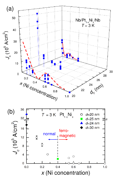
Nb/Pt1-xNix/Nb junctions with different and were fabricated and studied, see Table II. An example of modulation for Nb/PtNi/Nb JJ can be found in Fig. 4 of Ref. Golod_2010 . Figure 7 (a) shows measured (K) for Nb/Pt1-xNix/Nb junctions versus Ni concentration and interlayer thickness. Fig. 7 (b) shows projection of this data to the - plane. Generally, decreases both with increasing and . However, it decreases non-monotonously. Oscillatory decay of vs. in SFS junctions is well documented and is caused by sequential 0- transitions Ryazanov_2001 ; Oboznov_2006 ; Robinson_2007 ; Kontos_2002 .
From Fig. 7 it can be seen that for a given the is decaying non-monotonously with increasing Ni concentration , as indicated by dashed red lines in Fig. 7 (a) for and 30 nm. We attribute such oscillatory behavior to 0- transitions at a given upon increasing the ferromagnetic exchange energy . The increase of Ni concentration leads to the enhancement of , which leads to the shrinking of and cause the 0- transition. As described above, ferromagnetism in Pt1-xNix films appears at the critical concentration . We observe that the relative spread in values increases in JJ’s with the ferromagnetic interlayer . Most likely this is also a consequence of a rapid shrinkage of down to about nm, comparable to the roughness of our films, see Fig. 4.
IV.4 Appendix D. Interface resistances in Nb/Pt1-xNix/Nb junctions
Figure 8 (a) shows a 3D plot of measured normal resistivities, , of studied Nb/Pt1-xNix/Nb junctions versus Ni concentration and interlayer thickness. Parameters of JJ’s are listed in Table III. Here , where is the junction area. Fig. 8 (b) shows the 2D projection of same data. It is seen that greatly increases at which is correlated with the region with maximal longitudinal resistance of PtNi films, see Fig. 6 (c). Thus frustration and disorder is directly reflected in junction characteristics. However, exhibits a much larger peaks at the frustration points and , compared to . Especially at the onset of ferromagnetism , where increases by almost an order of magnitude. This indicates that properties of SFS junctions depend not only on the electronic disorder (m.f.p.) but also on the magnetic disorder and, particularly, are affected by quantum fluctuations at the quantum phase transition reflected by the sign-change of the AHE, Fig. 6 (a).

From the comparison of and , Figs. 6 (c) and 8 (b) it is also seen that junction resistivity is several times larger than the film resistivity. This indicates that junction resistances are dominated by an additional resistance at S/F interfaces due to a finite interface transparency . For SNS junctions the interface transparency is reduced by a mismatch between Fermi velocities and Fermi surfaces (electronic band structures) of S and N metals Krasnov_1992 ; Buhrman_1998 . For example, the transparency of Nb/Cu interface was estimated to be Krasnov_1992 . The transparency of S/F interfaces is further reduced due to spin imbalance, which affects the Andreev reflection of spin-singlet Cooper pairs from spin-polarized ferromagnet Beenakker_1995 ; Aarts_1997 ; Buhrman_1998 ; Falko_1999 ; Golubov_1999 ; Bourgeois_2001 ; Turek_2002 ; Tagirov_2003 ; Yao_2003 . The values cm2 in our junctions, see Tables I-III, are comparable to the value cm2 reported for Nb/Co interfaces Yao_2003 . From Table III it can be seen that for Nb/Pt1-xNix/Nb JJ’s with and 0.6, corresponding to quantum critical points of vanishing AHE, , see Fig. 6 (a) and Ref. Golod_2013b , the value and, thus, the interface resistance greatly increases. Simultaneously the critical current density increases, leading to extraordinary large products of several hundreds of V, comparable to that for SINIS (I-insulator) junctions Golubov_1995 . The origin of this phenomenon remains to be understood. So far we can only speculate that anomalous junction characteristics at these critical concentrations are related to quantum phase transitions occurring between ordered and phases with different magnetic properties Mokrousov_2011 ; Dahmani_1985 ; Hizi_2019 ; Chen_2011 . For all our junctions, is dominated by S/F interface resistances, consistent with earlier reports for other types of S/F interfaces Buhrman_1998 ; Bourgeois_2001 ; Yao_2003 . Therefore, there are significant barriers at S/F interfaces, despite the deposition of SFS trilayers occurred in one run without breaking vacuum.
IV.5 Appendix E. Clarification about extraction of magnetization curves from AJF analysis
In derivation of Eq. (1) we assumed that has an in-plane orientation. Due to the small thickness of F-interlayers, they have negligibly small demagnetization factors. In this case the F-layer does not generate magnetic fields at S/F interfaces and, therefore, does not induce any additional flux in S-electrodes. This leads to a simple separation of flux contributions from S-electrodes and F-interlayer, represented by first and second terms in Eq. (1). Here in the first term does not contain (i.e it is not ) and differs from solely due to screening by superconducting currents and a finite demagnetization factor of S-electrodes, just like in the non-magnetic junction. Since for our junctions the total thickness of S-layers nm is comparable to junction sizes, the demagnetization factor of electrodes is non-negligible and the difference between and can be sensible. Nevertheless, this does not affect the linearity of curves above the saturation field because in the presence of the demagnetization effect. Therefore, subtraction of the linear asymptotics, shown by dashed lines in middle panels of Fig. 2 (a-c), remains unambiguous.
The distance between points in the AJF analysis is determined by the flux quantization field . It is smaller for the hard axis orientation of the field, corresponding to the longest size of the junction . Therefore, AJF curves for the hard axis, Figs. 2 (c,d), are much more detailed than for the easy axis orientation, Figs. 2 (a,b). Nevertheless, extraction of for the hard axis orientation is complicated by two factors: First, magnetization reversal in the hard axis orientation occurs initially via coherent rotation of magnetization (without hysteresis), followed by a small flip, and continuing coherent rotation towards the saturated state Iovan_2002 ; Ivanov_2013 ; Iovan_2017 ; Kapran_2020 . Since the flip is smaller than , it does not allow direct extraction of from the size of the magnetization jump. Second, since the length of the electrode m in the hard axis orientation is much larger than the London penetration depth of S-electrodes, nm, junctions are prone to penetration of Abrikosov vortices, which greatly distort junction characteristics Golod_2010 ; Golod_2019 . Therefore, the field range of our analysis is limited by the range of the Meissner state.
For the JJ with nm, Fig. 2 (c), the Meissner state persists up the the saturation state and the straightforward subtraction of the high-field linear slope from the AJF curves, shown by the dashed line in the middle panel of Fig. 2 (c), provides a magnetization loop with the expected saturation at high fields, as shown in the bottom panel of Fig. 2 (c). It can be seen that saturation occurs at kOe, which is consistent with that obtained using the first-order reversal curves analysis on the same junction, see Fig. 2 (f) in Ref. Kapran_2020 .
For the JJ with nm, Fig. 2 (d), the field range is limited by entrance of Abrikosov vortices. It is smaller than 1 kOe and the saturation is presumably not reached, which does not allow unambiguous determination of the linear asymptotics. In this case we have chosen to assume in Eq. (1) and calculate the first linear term using the definition of the magnetic thickness, , where nm are is the thicknesses and nm are the London penetration depths of the two Nb-electrodes. The corresponding linear dependence is shown by the dashed line in the middle panel of Fig. 2 (d). Thus obtained magnetization curve, , shown in the bottom panel of Fig. 2 (d), is in line with the expected magnetization curve for the hard axis orientation, as discussed above, and provides a correct value of .
References
- (1) M. J. M. de Jong and C. W. J. Beenakker, Andreev Reflection in Ferromagnet-Superconductor Junctions, Phys. Rev. Lett. 74, 1657 (1995).
- (2) E.A. Demler, G.B. Arnold, M.R. Beasley, Superconducting proximity effects in magnetic metals, Phys. Rev. B 55, 15174 (1997).
- (3) A. Kadigrobov, R. I. Shekhter and M. Jonson, Quantum spin fluctuations as a source of long-range proximity effects in diffusive ferromagnet-superconductor structures. Europhys. Lett. 54, 394 (2001).
- (4) B. P. Vodopyanov, and L. R. Tagirov, Andreev Conductance of a Ferromagnet/Superconductor Point Contact, JETP Lett. 77, 126-131 (2003).
- (5) J. Kopu, M. Eschrig, J. C. Cuevas, and M. Fogelström, Transfer-matrix description of heterostructures involving superconductors and ferromagnets. Phys. Rev. B 69, 094501 (2004).
- (6) A. I. Buzdin, Proximity effects in superconductor-ferromagnet heterostructures. Rev. Mod. Phys. 77, 935-976 (2005).
- (7) F. S. Bergeret, A. F. Volkov, and K. B. Efetov, Odd triplet superconductivity and related phenomena in superconductor-ferromagnet structures. Rev. Mod. Phys. 77, 1321-1373 (2005).
- (8) M. Božović and Z. Radović, Ferromagnet-superconductor proximity effect: The clean limit, Europhys. Lett. 70, 513?519 (2005). DOI: 10.1209/epl/i2004-10511-0
- (9) Y. Asano, Y. Sawa, Y. Tanaka, and A.A. Golubov, Odd triplet superconductivity and related phenomena in superconductor-ferromagnet structures. Phys. Rev. B 76, 224525 (2007).
- (10) M. A. Silaev, Possibility of a long-range proximity effect in a ferromagnetic nanoparticle. Phys. Rev. B 79, 184505 (2009).
- (11) Ya. V. Fominov, A. A. Golubov, T. Yu. Karminskaya, M. Yu. Kupriyanov, R. G. Deminov, and L. R. Tagirov, Superconducting Triplet Spin Valve. JETP Lett. 91, 308 (2010).
- (12) F. Konschelle, J. Cayssol and A. Buzdin, Long-range singlet proximity effect in ferromagnetic nanowires, Phys. Rev. B 82, 180509(R) (2010).
- (13) M. Alidoust, J. Linder, G. Rashedi, T. Yokoyama, and A. Sudbø, Spin-polarized Josephson current in superconductor/ferromagnet/superconductor junctions with inhomogeneous magnetization, Phys. Rev. B 81, 014512 (2010).
- (14) N. G. Pugach, M. Yu. Kupriyanov, E. Goldobin, R. Kleiner, and D. Koelle, Superconductor-insulator-ferromagnet-superconductor Josephson junction: From the dirty to the clean limit, Phys. Rev. B 84, 144513 (2011).
- (15) A.S. Mel’nikov, A.V. Samokhvalov, S.M. Kuznetsova, and A.I. Buzdin, Interference Phenomena and Long-Range Proximity Effect in Clean Superconductor-Ferromagnet Systems. Phys. Rev. Lett. 109, 237006 (2012).
- (16) S. H. Jacobsen and J. Linder, Giant triplet proximity effect in -biased Josephson junctions with spin-orbit coupling, Phys. Rev. B 92, 024501 (2015).
- (17) I. V. Bobkova, A. M. Bobkov, and M. A. Silaev, Gauge theory of the long-range proximity effect and spontaneous currents in superconducting heterostructures with strong ferromagnets, Phys. Rev. B 96, 094506 (2017).
- (18) N. Klenov, Y. Khaydukov, S. Bakurskiy, R. Morari, I. Soloviev, V. Boian, T. Keller, M. Kupriyanov, A. Sidorenko, and B. Keimer, Periodic Co/Nb pseudo spin valve for cryogenic memory, Beilstein J. Nanotechnol. 10, 833-839 (2019). doi:10.3762/bjnano.10.83
- (19) V. T. Petrashov, I. A. Sosnin, I. Cox, A. Parsons, and C. Troadec, Giant Mutual Proximity Effects in Ferromagnetic/Superconducting Nanostructures, Phys. Rev. Lett. 83, 3281 (1999).
- (20) V. V. Ryazanov, V. A. Oboznov, A.Yu. Rusanov, A. V. Veretennikov, A. A. Golubov, and J. Aarts, Coupling of Two Superconductors through a Ferromagnet: Evidence for a Junction, Phys. Rev. Lett. 86, 2427 (2001).
- (21) J. Aumentado and V. Chandrasekhar, Mesoscopic ferromagnet-superconductor junctions and the proximity effect, Phys. Rev. B 64, 054505 (2001).
- (22) T. Kontos, M. Aprili, J. Lesueur, F. Genêt, B. Stephanidis, and R. Boursier, Josephson Junction through a Thin Ferromagnetic Layer: Negative Coupling, Phys. Rev. Lett. 89, 137007 (2002).
- (23) V. A. Oboznov, V.V. Bol’ginov, A. K. Feofanov, V.V. Ryazanov, and A. I. Buzdin, Thickness Dependence of the Josephson Ground States of Superconductor-Ferromagnet-Superconductor Junctions, Phys. Rev. Lett. 96, 197003 (2006).
- (24) F. Born, M. Siegel, E. K. Hollmann, H. Braak, A. A. Golubov, D. Yu. Gusakova and M. Yu. Kupriyanov, Multiple transitions in superconductor/insulator/ferromagnet/superconductor Josephson tunnel junctions, Phys. Rev. B 74, 140501(R) (2006).
- (25) R. S. Keizer, S. T. B. Goennenwein, T. M. Klapwijk, G. Miao, G. Xiao, and A. Gupta, A spin triplet supercurrent through the half-metallic ferromagnet CrO2, Nature (London) 439, 825 (2006).
- (26) J. W. A. Robinson, S. Piano, G. Burnell, C. Bell, and M. G. Blamire, Zero to transition in superconductor-ferromagnet-superconductor junctions, Phys. Rev. B 76, 094522 (2007).
- (27) A. A. Bannykh, J. Pfeiffer, V. S. Stolyarov, I. E. Batov, V. V. Ryazanov, and M. Weides, Josephson tunnel junctions with a strong ferromagnetic interlayer, Phys. Rev. B 79, 054501 (2009).
- (28) J.W.A. Robinson, G.B. Halász, A.I. Buzdin, and M.G. Blamire, Enhanced Supercurrents in Josephson Junctions Containing Nonparallel Ferromagnetic Domains, Phys. Rev. Lett. 104, 207001 (2010).
- (29) M. Flokstra, J. M. van der Knaap, and J. Aarts, Magnetic coupling in superconducting spin valves with strong ferromagnets. Phys. Rev. B 82, 184523 (2010).
- (30) J. Wang, M. Singh, M. Tian, N. Kumar, B. Liu, C. Shi, J. K. Jain, N. Samarth, T. E. Mallouk, and M. H.W. Chan, Interplay between superconductivity and ferromagnetism in crystalline nanowires, Nat. Phys. 6, 389 (2010).
- (31) K. M. Boden, W. P. Pratt Jr., and N.O. Birge, Proximity-induced density-of-states oscillations in a superconductor/strong-ferromagnet system, Phys. Rev. B 84, 020510(R) (2011).
- (32) V.V. Bol’ginov, V.S. Stolyarov, D.S. Sobanin, A.L. Karpovich, and V.V. Ryazanov, Magnetic Switches Based on NbPdFeNb Josephson Junctions with a Magnetically Soft Ferromagnetic Interlayer JETP Lett. 95, 366-371 (2012).
- (33) T. Golod, A. Rydh, V. M. Krasnov, I. Marozau, M. A. Uribe- Laverde, D. K. Satapathy, Th. Wagner, and C. Bernhard, High bias anomaly in YBa2Cu3O7-x/LaMnO3+δ/YBa2Cu3O7-x superconductor/ferromagnetic insulator/superconductor junctions: Evidence for a long-range superconducting proximity effect through the conduction band of a ferromagnetic insulator, Phys. Rev. B 87, 134520 (2013).
- (34) B. Baek, W.H. Rippard, S.P. Benz, S.E. Russek, and P.D. Dresselhaus Hybrid superconducting-magnetic memory device using competing order parameters Nat. Commun. 5, 3888 (2014).
- (35) M. Kompaniiets, O. V. Dobrovolskiy, C. Neetzel, E. Begun, F. Porrati, W. Ensinger, and M. Huth, Proximity-induced superconductivity in crystalline Cu and Co nanowires and nanogranular Co structures. J. App. Phys. 116, 073906 (2014).
- (36) A. Iovan, T. Golod, and V. M. Krasnov, Controllable generation of a spin-triplet supercurrent in a Josephson spin valve, Phys. Rev. B 90, 134514 (2014).
- (37) D. Lenk, V. I. Zdravkov, J.-M. Kehrle, G. Obermeier, A. Ullrich, R. Morari, H.-A. Krug von Nidda, C. Müller, M. Yu. Kupriyanov, A. S. Sidorenko, S. Horn, R. G. Deminov, L. R. Tagirov and R. Tidecks, Thickness dependence of the triplet spin-valve effect in superconductor-ferromagnet-ferromagnet heterostructures. Beilstein J. Nanotechnol. 7, 957 (2016).
- (38) K. Lahabi, M. Amundsen, J. A. Ouassou, E. Beukers, M. Pleijster, J. Linder, P. Alkemade, and J. Aarts. Controlling supercurrents and their spatial distribution in ferromagnets. Nature Commun. 8, 2056 (2017).
- (39) N.O. Birge, Spin-triplet supercurrents in Josephson junctions containing strong ferromagnetic materials, Phil. Trans. R. Soc. A 376, 20150150 (2018). http://dx.doi.org/10.1098/rsta.2015.0150
- (40) O. V. Skryabina, S. N. Kozlov, S. V. Egorov, A. A. Klimenko, V. V. Ryazanov, S. V. Bakurskiy, M. Yu. Kupriyanov, N. V. Klenov, I. I. Soloviev, A. A. Golubov, K. S. Napolskii, I. A. Golovchanskiy, D. Roditchev and V. S. Stolyarov, Anomalous magneto-resistance of Ni-nanowire/Nb hybrid system, Sc. Rep. 9, 14470 (2019). https://doi.org/10.1038/s41598-019-50966-8
- (41) O. M. Kapran, A. Iovan, T. Golod, and V. M. Krasnov, Observation of the dominant spin-triplet supercurrent in Josephson spin valves with strong Ni ferromagnets. Phys. Rev. Research 2, 013167 (2020).
- (42) J. Linder and A. V. Balatsky, Odd-frequency superconductivity. Rev. Mod. Phys. 91, 045005 (2019).
- (43) T. Golod, A. Rydh and V. M. Krasnov, Anomalous Hall effect in NiPt thin films, J. Appl. Phys. 110, 033909 (2011).
- (44) T. Golod, A. Rydh, P. Svedlindh and V. M. Krasnov, Anti-ordinary Hall effect near the ferromagnetic quantum phase transition in NixPt1-x thin films, Phys. Rev. B 87, 104407 (2013).
- (45) T. Golod, A. Rydh, and V.M. Krasnov, Detection of the Phase Shift from a Single Abrikosov Vortex. Phys. Rev. Lett. 104, 227003 (2010).
- (46) A. Iovan and V. M. Krasnov, Signatures of the spin-triplet current in a Josephson spin valve: A micromagnetic analysis. Phys. Rev. B 96, 014511 (2017).
- (47) V.M. Krasnov, V.A. Oboznov, and N.F. Pedersen, Fluxon dynamics in long Josephson junctions in the presence of a temperature gradient or spatial nonuniformity, Phys. Rev. B 55, 14486-14498 (1997).
- (48) A. T. Aldred, Temperature dependence of the magnetization of nickel, Phys. Rev. B 11, 2597 (1975).
- (49) H. Danan, A. Herr, and A. J. P. Meyer, New Determinations of the Saturation Magnetization of Nickel and Iron, J. Appl. Phys. 39, 669 (1968); DOI: https://doi.org/10.1063/1.2163571.
- (50) A. A. Golubov, M. Yu. Kupriyanov, and E. Il’ichev, The current-phase relation in Josephson junctions, Review of Modern Physics 76, 411-469 (2004).
- (51) A. A. Golubov and V. M. Krasnov, The first critical field, , and the penetration depth in dirty superconducting S/N multilayers, Physica C 196, 177-184 (1992).
- (52) C. E. Dahmani, M. C. Cadeville, J. M. Sanchez, and J. L. Moran-Lopez, Ni-Pt Phase Diagram: Experiment and Theory, Phys. Rev. Lett. 55, 1208 (1985).
- (53) M. J. Besnus and A. Herr, Transition from ferromagnetism to paramagnetism in Ni-Pt alloys, Phys. Lett. A 39, 83 (1972).
- (54) A. Hizi, H. Garbouj, C. Mottet, M. Said, Chemical ordering and surface segregation in Ni1-cPtc system: A theoretical study from the alloys to the nanoalloys, Results in Physics 14, 102493 (2019).
- (55) N. Nagaosa, J. Sinova, S. Onoda, A. H. MacDonald, and N. P. Ong, Anomalous Hall effect, Rev. Mod. Phys. 82, 1539 (2010).
- (56) H. Zhang, S. Blügel, and Yu. Mokrousov, Anisotropic intrinsic anomalous Hall effect in ordered 3dPt alloys, Phys. Rev. B 84, 024401 (2011).
- (57) V. M. Krasnov, V. A. Oboznov and V. V. Ryazanov, Anomalous temperature dependence of in superconducting Nb/Cu multilayer, Physica C 196, 335-339 (1992).
- (58) S. K. Upadhyay, A. Palanisami, R. N. Louie, and R. A. Buhrman, Probing Ferromagnets with Andreev Reflection, Phys. Rev. Lett. 81, 3247 (1998).
- (59) J. Aarts, J. M. E. Geers, E. Brück, A. A. Golubov, and R. Coehoorn, Interface transparency of superconductor/ferromagnetic multilayers, Phys. Rev. B 56, 2779 (1997).
- (60) V. I. Fal’ko and C. J. Lambert, and A. F. Volkov, Andreev reflections and magnetoresistance in ferromagnet/superconductor mesoscopic structures, JETP Lett. 69, 532 (1999).
- (61) A. A. Golubov, Interface resistance in ferromagnetrsuperconductor junctions, Physica C 326-327, 46-52 (1999).
- (62) O. Bourgeois, P. Gandit, A. Sulpice, J. Lesueur and X. Grison, Transport in superconductor/ferromagnet/superconductor junctions dominated by interface resistance, Phys. Rev. B 63, 064517 (2001).
- (63) K. Xia, P. J. Kelly, G. E. W. Bauer, and I. Turek, Spin-Dependent Transparency of Ferromagnet/Superconductor Interfaces, Phys. Rev. Lett. 89, 166603 (2002).
- (64) S. F. Lee, S. Y. Huang, J. H. Kuo, Y. A. Lin, L. K. Lin, and Y. D. Yao, Quantitative analysis of interface resistance in Co/Nb multilayers for normal and superconducting Nb, J. Appl. Phys. 93, 8212 (2003).
- (65) A. A. Golubov, E.P. Houwman, J. G. Gijsbertsen, V. M. Krasnov, J. Flokstra, and H. Rogalla, Proximity effect in superconductor-insulator-superconductor Josephson tunnel junctions: Theory and experiment, Phys. Rev. B 51, 1073 (1995).
- (66) M. Chen, Z. Shi, W.J. Xu, X.X. Zhang, J. Du, and S.M. Zhou, Tuning anomalous Hall conductivity in L10 FePt films by long range chemical ordering, Appl. Phys. Lett. 98, 082503 (2011).
- (67) Y. Henry, A. Iovan, J.-M. George, and L. Piraux, Statistical analysis of the magnetization processes in arrays of electrodeposited ferromagnetic nanowires, Phys. Rev. B 66, 184430 (2002).
- (68) Yu. P. Ivanov, O. Iglesias-Freire, E. V. Pustovalov, O. Chubykalo-Fesenko, and A. Asenjo, Magnetic configurations of Co(111) nanostripes with competing shape and crystalline anisotropies, Phys. Rev. B 87, 184410 (2013).
- (69) T. Golod, A. Pagliero and V. M. Krasnov, Two mechanisms of Josephson phase shift generation by an Abrikosov vortex, Phys. Rev. B 100, 174511 (2019).
- (70) For in-plane transport the electronic m.f.p. is limited by the film thickness due to interface scattering. However, here we consider perpendicular transport, for which such scattering is irrelevant. Therefore, the effective m.f.p. in the perpendicular direction is not limited by the film thickness.