Direct and inverse spin-orbit torques in antiferromagnetic and ferromagnetic FeRh/W(001)
Abstract
We use ab-initio calculations to investigate spin-orbit torques (SOTs) in FeRh(001) deposited on W(100). Since FeRh undergoes a ferromagnetic-antiferromagnetic phase transition close to room temperature, we consider both phases of FeRh. In the antiferromagnetic case we find that the effective magnetic field of the even torque is staggered and therefore ideal to induce magnetization dynamics or to switch the antiferromagnet (AFM). At the antiferromagnetic resonance the inverse SOT induces a current density, which can be determined from the SOT. In the ferromagnetic case our calculations predict both even and odd components of the SOT, which can also be used to describe the ac and dc currents induced at the ferromagnetic resonance. For comparison we compute the SOTs in the c() AFM state of Fe/W(001).
I Introduction
Switching of the Néel vector in antiferromagnets (AFMs) by the spin-orbit torque (SOT) is promising to achieve higher writing rates on the terahertz scale in magnetic memory devices (See Refs. [1, 2, 3] for recent reviews). Additionally, AFM magnetic memory allows higher data density than its ferromagnet (FM) counterpart. Moreover, it has been proposed that SOT triggers self-sustained THz oscillations in AFMs [4]. Néel vector switching through SOT has been demonstrated experimentally first in the bulk antiferromagnets (AFMs) CuMnAs [5] and Mn2Au [6]. Planar Hall effect and magnetoresistance may be used to read the state of the AFM bit in the memory device and they have also been used to obtain an indirect proof of AFM switching. Direct evidence of AFM switching is available through -ray magnetic linear dichroism-photoemission electron microscopy [6].
Experimentally, it has been shown that the Néel order can be switched by the SOT also in bilayers composed of a heavy metal layer (HM) and an AFM layer, such as Pt/Fe2O3 [7]. However, it has been pointed out that measurements of planar Hall effect and magnetoresistance in HM/AFM bilayers do not always provide clear evidence of AFM switching [8, 9]. Most SOT switching experiments on HM/AFM bilayers considered insulating AFMs, such as NiO. In CoO/Pt and Fe2O3/Pt bilayers a thermomagnetoelastic mechanism rather than the SOT has been identified as dominating mechanism for current-induced switching [8, 10].
In this paper we study the SOT in FeRh/W(001) bilayers. This choice is motivated by three key assets of this system: (i) The use of W in magnetic bilayers leads to large SOTs [11, 12]. (ii) Epitaxial layers of FeRh(001) can be deposited on W(001) single crystals [13]. (iii) FeRh has gained considerable interest in the spintronics community. Since it exhibits an AFM-FM phase transition close to room temperature, femtosecond laser-pulses have been used to study this phase transition at sub-picosecond timescales [14]. The AFM-FM phase transition in FeRh has also been used to tune the damping dynamically [15]. Lateral spin-pumping between FM and AFM domains has been found to be crucial for the damping enhancement [16]. When FeRh/Pt is excited by femtosecond laser pulses superdiffusive spin currents are generated in FeRh and converted into a charge current by the inverse spin Hall effect, which leads to a measurable THz signal [17, 18, 19]. This THz signal varies strongly as FeRh goes through the AFM-FM phase transition because it is suppressed in the AFM state of FeRh. Similarly, the Hall effect changes significantly across the AFM-FM phase transition [20].
Phenomenology suggests that the antiferromagnetic resonance is accompanied by spin-pumping and that conversely spin current from the spin Hall effect injected into an AFM layer exerts staggered effective magnetic fields on it, which are efficient to induce magnetization dynamics in the AFM [21, 22, 23]. However, these concepts have not yet been investigated by ab-initio methods. Therefore, in this paper we investigate direct and inverse spin-orbit torques in FeRh/W(001) based on first-principles density-functional theory calculations. The direct SOT describes the effective magnetic fields acting on the magnetic moments when an electric current is applied, which may excite magnetization dynamics or switch the AFM or FM magnetization. The inverse SOT [24, 25] describes the electric current induced by magnetization dynamics and is therefore related to vertical spin pumping, which has been investigated experimentally in the similar system of FeRh/Pt [16]. The inverse SOT is also related to the helicity-dependent component of the THz signal that follows excitation by a fs laser-pulse, and which was measured experimentally in FeRh/Pt as well [19, 18]. For comparison we compute the SOTs also in an Fe monolayer on W(001), which exhibits a c() AFM configuration [26] and is therefore compensated like FeRh.
This paper is structured as follows. In Sec. II we explain first our computational formalism for the direct SOT (Sec. II.1), followed by the formalism for the inverse SOT (Sec. II.2). In Sec. III we discuss our ab-initio results in the following order: In Sec. III.1 we specify the computational details, and in Sec. III.2 and Sec. III.3 we present our results on the even and odd direct SOT, respectively, which we obtained in the AFM phase of FeRh/W(001). We discuss the inverse SOT in the AFM phase of FeRh/W(001) in Sec. III.4. Next, Sec. III.5 is devoted to the direct and inverse SOT in the FM phase of FeRh/W(001). Finally, Sec. III.6 treats the SOT in Fe/W. This paper ends with a summary in Sec. IV.
II Formalism
II.1 Direct SOT
In order to compute the SOT we use the formalism described in Ref. [12]. The torque on atom can be expressed in terms of the torkance tensor as
| (1) |
where is the -th component of the applied electric field and is a unit vector pointing into the -th Cartesian direction. We separate the torkance into even and odd parts with respect to inversion of the magnetization direction. Since we study antiferromagnets in this work we consider the atom-resolved torkances , where the index selects the atom. The even torkance is given by
| (2) | ||||
and the odd torkance is given by
| (3) |
where is the number of -points used to sample the Brillouin zone, is the -th cartesian component of the torque operator of atom , is the -th cartesian component of the velocity operator, is the quasiparticle broadening, and and denote the Bloch function for band at -point and the corresponding band energy, respectively.
Experimental works on the SOT typically discuss the effective magnetic field that one would have to apply in order to generate a torque of the same size as the SOT. For a given torque this effective magnetic field may be computed from
| (4) |
where is the magnetic moment of atom and is its direction. In order to switch an antiferromagnet, the effective magnetic field needs to be staggered, i.e., its sign needs to be opposite between antiparallel magnetic moments.
II.2 Inverse SOT
While the direct SOT is the generation of a torque on the magnetization when an electric field is applied, the inverse SOT is the induction of a current density by magnetization dynamics [24, 25]. When this current density is expressed in terms of the atom-resolved torkance, Eq. (2) and Eq. (3), a summation over the atomic site index is required:
| (5) |
where the superscript is set to ’even’ and ’odd’ to address the even inverse SOT and the odd inverse SOT, respectively. When the total inverse SOT is meant, is left blank.
In antiferromagnets with two sublattices we introduce the two vectors
| (6) |
and
| (7) |
where and are the magnetization directions on the two sublattices, which we denote by and , respectively. These vectors satisfy . Similarly, we define the two torkances
| (8) |
and
| (9) |
With these definitions the pumped charge current density in a 2-sublattice AFM can be written as
| (10) | ||||
At the antiferromagnetic resonance the two magnetization directions and precess with slightly different cone angles, which results in a non-zero vector [27]. However, usually is satisfied, which can be used to replace Eq. (10) by approximated expressions. For a layerwisely compensated layered AFM in an AFM/HM bilayer with two magnetic sublattices we can approximate
| (11) |
where and are the two torkances of the two sublattices in layer of the AFM and
| (12) |
is the generalization of Eq. (6) to a layerwisely compensated layered AFM. Therefore, in this case the even component of the pumped current density can be approximated as
| (13) |
where we further approximated . Similarly, we approximately obtain
| (14) |
because
| (15) |
when for a layerwisely compensated layered AFM in an AFM/HM bilayer.
III Results
III.1 Computational details
It has been shown in experiments that ultrathin epitaxial layers of FeRh(001) can be deposited on W(100) single-crystals [13]. Since the mismatch between the FeRh (CsCl structure) bulk lattice constant of 2.99 Å and the one of bcc W of Å is 5%, pseudomorphic growth of the FeRh(001) layer leads to tetragonal distortion.
We use the film mode [29] in the ab-initio program FLEUR [30] in order to compute the electronic structure of FeRh on W. In this mode the unit cell is repeated periodically only in the in-plane directions and the resulting film structure is embedded into vacuum. Since systems with inversion symmetry take less computational effort in the film mode we consider the centrosymmetric system FeRh/W/FeRh, where 11 layers of W(001) are sandwiched between two layers of FeRh on both sides. In Fig. 1 we show the corresponding unit cell.
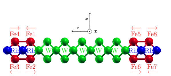
In order to compute the antiferromagnetic state we need a magnetic unit cell with in-plane area twice as large as the one of the crystal unit cell. Therefore, we set the in-plane lattice constant to , where is Bohr’s radius. In our calculations, the inter-layer distance is in W and in FeRh. The distance between the W layer and the Fe layer at the interfaces is 2.83. We chose muffin-tin radii of in Fe and Rh and of in W and performed the calculations with the generalized gradient approximation [31] to density-functional theory. Spin-orbit coupling is included in the calculations. The magnetic moments are 2.63 in Fe1 and Fe2, while they are 3.21 in Fe3 and Fe4.
The computational parameters used in our calculations of a monolayer of Fe on W(001) (we refer to this system simply by Fe/W(001) in the following) are given in Ref. [26]. Also in this case we compute the inversion symmetric system Fe/W/Fe in order to reduce the numerical effort.
In order to evaluate the SOT according to Eq. (2) and Eq. (3) we make use of Wannier interpolation [32] for computational speed-up. For this purpose we disentangle 18 maximally localized Wannier functions per transition metal atom, where we employ our interface [33] between FLEUR and the Wannier90 program [34].
III.2 Even torkance
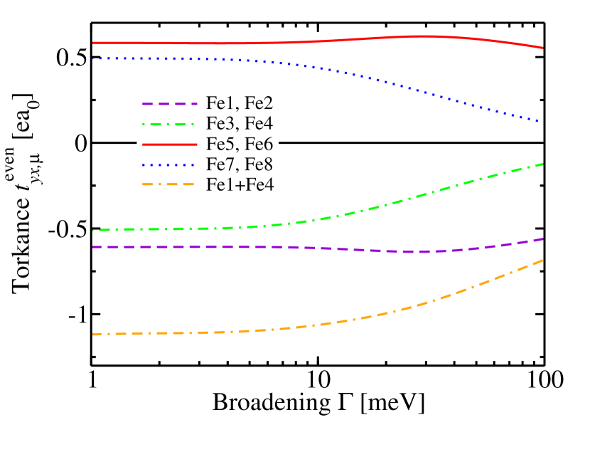
We show the atom-resolved even torkance in Fig. 2. While the magnetic moments in Fe1 and Fe2 are aligned antiferromagnetically, their torkances agree: . Similary, the torkances agree on atoms Fe3 and Fe4, i.e., . This property of layerwisely compensated layered AFMs is the basis for Eq. (11). Additionally, the four torkances on atoms Fe1 through Fe4 all have the same sign. Consequently, the effective magnetic field, Eq. (4) is staggered, i.e., it has opposite sign on Fe1 through Fe4 between magnetic moments that point in opposite directions. Such a staggered effective magnetic field is precisely what is necessary to switch the antiferromagnetic layer composed of Fe1 through Fe4.
Fig. 2 also shows that the torques on Fe5 and Fe6 are equal but opposite to the torques on Fe1 and Fe2. Similarly, the torques on Fe7 and Fe8 are equal but opposite to the torques on Fe3 and Fe4. This follows from the fact that the space inversion operation maps Fe1 on Fe5, Fe4 on Fe8, Fe2 on Fe6, and Fe3 on Fe7. We only show the -component of the torkance, because the and components are zero. The -component may be obtained from .
In the limit we find the torkances and . At high quasiparticle broadening meV the torkance on Fe4 is significantly reduced, namely , while the torkance on Fe1 is still of similar magnitude, namely . In Ref. [12] we have shown that the even torkance is described by a scattering-independent mixed Berry curvature in the limit . This predicts the even torkance to be -independent at small . Indeed at small , e.g. meV, both torkances are roughly constant.
In Ref. [12] we determined the even torkance to be in Mn(1)/W(9) and in Mn(1)/W(15) in the limit , while at meV we found the torkance to be in both Mn/W(001) systems. Since the in-plane unit cell area of FeRh/W/FeRh is twice as large as the one of Mn/W(001) we need to compute in order to perform a meaningful comparison of torkances between FeRh/W/FeRh and W/Mn(001), i.e., we have to consider half of the total torque on Fe1 through Fe4. This sum is also shown in Fig. 2. We find in the limit and at meV. Thus, the torkances in FeRh/W/FeRh are larger than in W/Mn. However, since the sign of the torkances agrees between the two systems, and since the magnitudes are similar, we assume that the even SOT is generated by the same mechanism in both systems. In Ref. [12] we have shown that the even SOT in W/Mn arises from spin currents and may be attributed to the spin Hall effect from W. Therefore, we attribute the even torque in FeRh/W/FeRh also to spin currents from the SHE of W.
The quasiparticle broadening also determines the effective spin-diffusion length. Consequently, we assume that decays stronger with increasing than because the Fe4 is further away from W than Fe1 and therefore a larger fraction of spin current is lost for high before the spin current reaches Fe4.
III.3 Odd torkance
In Fig. 3 we show the odd torkance. We only show the component , because due to symmetry the and components are zero and . For atoms related by space inversion, e.g. Fe1 and Fe5, the torques are again equal but opposite. The magnetic moments on Fe1 and Fe2 are antiparallel, but the odd torkances at these sites are opposite as well. Consequently, the effective field is not staggered for atoms Fe1 and Fe2. Similarly, the magnetic moments on Fe3 and Fe4 are antiparallel and their torkances are opposite such that the effective field is not staggered for these two atoms either. This is a property of layerwisely compensated layered AFMs, which we expressed also in Eq. (15).
On the other hand, Fe1 and Fe4 are antiparallel, their odd torkances are not staggered, but their effective fields are staggered. Similarly, Fe2 and Fe3 are antiparallel, their odd torkances are not staggered, but their effective fields are staggered. In order to induce magnetization dynamics in an AFM, the effective field should ideally be staggered consistently in the AFM. This criterion is not satisfied by the odd torkance in this system. The total torkance on Fe1, Fe2, Fe3, and Fe4 is zero for the odd torque, in contrast to the even torque discussed in the previous section.
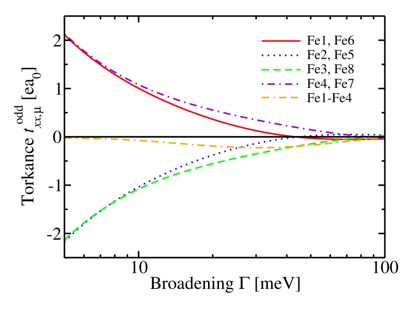
At small broadening the sign of is different to the one of in Mn/W(001), which we attribute to different interfacial spin-orbit interactions in the two systems. These differences may be described by opposite signs of the effective Rashba parameter in the two cases.
III.4 Inverse SOT
Previous works on spin-pumping in AFM/HM bilayers focused on the dc spin current pumped at the antiferromagnetic resonance [21, 22, 23]. This dc component is observed when the staggered magnetization is parallel to the bilayer interface. Here, we consider a different geometry (see Fig. 1) with staggered magnetization perpendicular to the bilayer interface. In this geometry only ac spin currents can be pumped. In FM/HM bilayers it has been pointed out that the pumped ac spin current is larger in magnitude than its dc counterpart [35]. AC spin currents can even be measured directly [36]. Moreover, only the phase-sensitive measurement of the ac inverse SOT allows us to access both its even and odd components [24, 25] in FM/HM bilayers.
Similarly, we expect the ac inverse SOT to induce larger voltages than its dc counterpart in the present AFM/HM bilayer. However, in the present case the odd part is not easy to access even in a phase-sensitive measurement of the ac inverse SOT, because it is approximately zero according to Eq. (14). This vanishing odd inverse SOT corresponds to the vanishing total odd torkance discussed in the previous Sec. III.3.
Assuming that precesses around the axis according to
| (18) |
at the antiferromagnetic resonance, we obtain from Eq. (13) the current densities
| (19) |
and
| (20) |
where
| (21) |
should be used to describe the current induced in FeRh/W(001), i.e., Fe5, Fe6, Fe7, and Fe8 have to be skipped in this summation, because in the centrosymmetric FeRh/W(001)/FeRh system the inverse SOT current density is zero if both the upper (Fe1-Fe4) and the lower (Fe5-Fe8) AFMs perform the same precession Eq. (18).
III.5 Ferromagnetic FeRh
When we flip all magnetic moments in the system, the even torkance on a given atom does not change, while the odd torkance on a given atom changes sign. This holds exactly, because the torkances in Eq. (2) and Eq. (3) are even and odd, respectively, with respect to inversion of magnetization, i.e., with respect to flipping all magnetic moments. When we flip only the magnetic moment of atom but keep all other magnetic moments unchanged, the even torque on atom stays approximately the same, while the odd torque on atom changes sign and stays approximately the same in magnitude. These relations hold only approximately, because by flipping only a single magnetic moment we obtain a new system that is not related by any symmetry operation to the original system. We may use these approximate relations in order to describe the ferromagnetic system. Thus, the even torkances shown in Fig. 2 for the AFM case apply approximately also to the FM case, i.e., the even torkances are approximately constant as FeRh passes through the AFM-FM phase transition. The torkance may therefore be used to describe the SOT in the FM case or to compute the voltage induced by the inverse SOT at the ferromagnetic resonance.
In order to obtain approximately the odd torkances for the FM case, i.e., the case in which the magnetic moments of Fe2, Fe4, Fe6, and Fe8 are flipped relative to what is shown in Fig. 1, we only need to flip the signs of the odd torkances of those atoms. The resulting total torkance on Fe1 and Fe4 is also shown in Fig. 3 (label ’Fe1-Fe4’). It is the difference between the odd torkance of Fe1 and the one of Fe4, because Fig. 3 discusses the torkances in the AFM phase and therefore we need to multiply the torkance of Fe4 by -1 if we use it to describe the FM case. Consequently, the sum of the odd torkances on Fe1 and Fe4 in the FM phase is approximated by the difference between the odd torkances on Fe1 and Fe4 in the AFM phase.
In FeRh/Pt the spin pumping and inverse dc SOT have been investigated experimentally across the AFM-FM phase transition [16]. Similarly, our results can be used to determine the ac and dc inverse SOT in the FM phase of FeRh/W. In the case of FMR-driven magnetization precession around the axis according to
| (22) |
we obtain the current densities [24]
| (23) |
and
| (24) |
Here, refers to the difference of torkances shown in Fig. 3 (label ’Fe-Fe4’).
In Ref. [19, 18] a helicity-dependent THz signal was measured in FeRh/Pt after illumination with a fs laser-pulse, which can be explained by the model described in Ref. [37]. Similarly, the odd torkance in the FM phase obtained from our calculations may also be used to predict a helicity-dependent THz signal in the similar system FeRh/W. For this purpose one may neglect the anisotropy of the odd torkance and apply our result for magnetization along to the case with in-plane magnetization.
III.6 Fe/W(001)/Fe
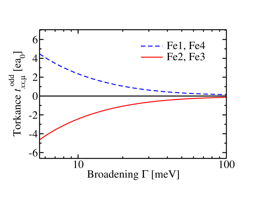
In our calculation there are two Fe monolayers in the c(22) AFM state that sandwich the W(001) layer. Each Fe monolayer is described by an in-plane unit cell containing two Fe atoms, which we label as follows: The top layer () in Fe/W(001)/Fe is composed of the atoms Fe1 and Fe2, while the bottom layer () is composed of the atoms Fe3 and Fe4. In Fig. 4 we show the even torkance in the AFM configuration. At high quasiparticle broadening meV we find the torkance , which is slightly smaller than the value found in Mn/W(001) of [12]. At meV we find , which is larger than found in Fe/Mn(110) studied in Ref. [38]. However, it is smaller than in FeRh/W/FeRh. The agreement in sign of the even torque between Mn/W(001), Fe/W(001), Fe/W(110) and FeRh/W(001)/FeRh suggests that it is dominated by the absorption of spin current from the spin Hall effect of W irrespective of W orientation (i.e., both in (001) and (110)) and for different FMs and AFMs, namely for Mn, Fe, and FeRh. However, this behaviour cannot be generalized to all magnets. For example, it has been shown that in Ni/W(110) the even torque arises from the orbital torque and that it is opposite in sign compared to Fe/W(110) [38].
In Fig. 5 we show the odd torkance in the AFM configuration. At high quasiparticle broadening meV we find the torkance , which is opposite in sign and larger in magnitude when compared with Mn/W, where we found [12]. However, the sign agrees with the one of in FeRh/W/FeRh. The sign agrees also with the one of Fe/W(110) studied in Ref. [38].

The inverse SOT in Fe/W may be obtained in the same way as discussed in Sec. III.4.
IV Summary
We use ab-initio calculations in order to study the SOT in FeRh/W(001) bilayers. Both the AFM and the FM phase of FeRh are interesting for spintronics applications. In the AFM phase the even SOT leads to a staggered effective field, which couples favourably to the staggered magnetization. In contrast, the effect of the odd torque in the AFM phase is negligible. We derive expressions for the inverse SOT in AFMs, i.e., formulas that express the current-density induced by magnetization dynamics in terms of the torkance tensors. We discuss the modifications of the torkance tensor as the system goes from the AFM state to the FM state. In the FM phase both even and odd SOT are significant, and both of them contribute to the ac inverse SOT at the ferromagnetic resonance. For comparison we also compute the SOTs in the c() AFM state of Fe/W(001), where we find smaller even torkances.
Acknowledgments
We acknowledge financial support from Leibniz Collaborative Excellence project OptiSPIN Optical Control of Nanoscale Spin Textures, and funding under SPP 2137 “Skyrmionics” of the DFG. We gratefully acknowledge financial support from the European Research Council (ERC) under the European Union’s Horizon 2020 research and innovation program (Grant No. 856538, project ”3D MAGiC”), from the DARPA TEE program through grant MIPR (No. HR0011831554) from DOI, and ITN Network COMRAD. The work was also supported by the Deutsche Forschungsgemeinschaft (DFG, German Research Foundation) TRR 173 268565370 (project A11), TRR 288 – 422213477 (projects B06). We also gratefully acknowledge the Jülich Supercomputing Centre and RWTH Aachen University for providing computational resources under project No. jiff40.
References
- Baltz et al. [2018] V. Baltz, A. Manchon, M. Tsoi, T. Moriyama, T. Ono, and Y. Tserkovnyak, Antiferromagnetic spintronics, Rev. Mod. Phys. 90, 015005 (2018).
- Manchon et al. [2019] A. Manchon, J. Železný, I. M. Miron, T. Jungwirth, J. Sinova, A. Thiaville, K. Garello, and P. Gambardella, Current-induced spin-orbit torques in ferromagnetic and antiferromagnetic systems, Rev. Mod. Phys. 91, 035004 (2019).
- Gomonay and Loktev [2014] E. V. Gomonay and V. M. Loktev, Spintronics of antiferromagnetic systems (review article), Low Temperature Physics 40, 17 (2014), https://doi.org/10.1063/1.4862467 .
- Cheng et al. [2016] R. Cheng, D. Xiao, and A. Brataas, Terahertz antiferromagnetic spin hall nano-oscillator, Phys. Rev. Lett. 116, 207603 (2016).
- Wadley et al. [2016] P. Wadley, B. Howells, J. Železný, C. Andrews, V. Hills, R. P. Campion, V. Novák, K. Olejník, F. Maccherozzi, S. S. Dhesi, S. Y. Martin, T. Wagner, J. Wunderlich, F. Freimuth, Y. Mokrousov, J. Kuneš, J. S. Chauhan, M. J. Grzybowski, A. W. Rushforth, K. W. Edmonds, B. L. Gallagher, and T. Jungwirth, Electrical switching of an antiferromagnet, Science 351, 587 (2016).
- Bodnar et al. [2019] S. Y. Bodnar, M. Filianina, S. P. Bommanaboyena, T. Forrest, F. Maccherozzi, A. A. Sapozhnik, Y. Skourski, M. Kläui, and M. Jourdan, Imaging of current induced éel vector switching in antiferromagnetic , Phys. Rev. B 99, 140409(R) (2019).
- Cheng et al. [2020] Y. Cheng, S. Yu, M. Zhu, J. Hwang, and F. Yang, Electrical switching of tristate antiferromagnetic éel order in epitaxial films, Phys. Rev. Lett. 124, 027202 (2020).
- Zhang et al. [2019] P. Zhang, J. Finley, T. Safi, and L. Liu, Quantitative study on current-induced effect in an antiferromagnet insulator/ bilayer film, Phys. Rev. Lett. 123, 247206 (2019).
- Chiang et al. [2019] C. C. Chiang, S. Y. Huang, D. Qu, P. H. Wu, and C. L. Chien, Absence of evidence of electrical switching of the antiferromagnetic éel vector, Phys. Rev. Lett. 123, 227203 (2019).
- Baldrati et al. [2020] L. Baldrati, C. Schmitt, O. Gomonay, R. Lebrun, R. Ramos, E. Saitoh, J. Sinova, and M. Kläui, Efficient spin torques in antiferromagnetic quantified by comparing field- and current-induced switching, Phys. Rev. Lett. 125, 077201 (2020).
- Pai et al. [2012] C.-F. Pai, L. Liu, Y. Li, H. W. Tseng, D. C. Ralph, and R. A. Buhrman, Spin transfer torque devices utilizing the giant spin hall effect of tungsten, Appl. Phys. Lett. 101, 122404 (2012).
- Freimuth et al. [2014] F. Freimuth, S. Blügel, and Y. Mokrousov, Spin-orbit torques in and magnetic bilayers from first principles, Phys. Rev. B 90, 174423 (2014).
- Lee et al. [2010] J.-S. Lee, E. Vescovo, L. Plucinski, C. M. Schneider, and C.-C. Kao, Electronic structure and magnetic properties of epitaxial ultrathin films on , Phys. Rev. B 82, 224410 (2010).
- Thiele et al. [2004] J.-U. Thiele, M. Buess, and C. H. Back, Spin dynamics of the antiferromagnetic-to-ferromagnetic phase transition in on a sub-picosecond time scale, Applied Physics Letters 85, 2857 (2004).
- Nan et al. [2020] T. Nan, Y. Lee, S. Zhuang, Z. Hu, J. D. Clarkson, X. Wang, C. Ko, H. Choe, Z. Chen, D. Budil, J. Wu, S. Salahuddin, J. Hu, R. Ramesh, and N. Sun, Electric-field control of spin dynamics during magnetic phase transitions, Science Advances 6, eabd2613 (2020).
- Wang et al. [2020] Y. Wang, M. M. Decker, T. N. G. Meier, X. Chen, C. Song, T. Grünbaum, W. Zhao, J. Zhang, L. Chen, and C. H. Back, Spin pumping during the antiferromagnetic–ferromagnetic phase transition of iron–rhodium, Nature Communications 11, 275 (2020).
- Seifert et al. [2017] T. Seifert, U. Martens, S. Günther, M. A. W. Schoen, F. Radu, X. Z. Chen, I. Lucas, R. Ramos, M. H. Aguirre, P. A. Algarabel, A. Anadon, H. S. Korner, J. Walowski, C. Back, M. R. Ibarra, L. Morellon, E. Saitoh, M. Wolf, C. Song, K. Uchida, M. Münzenberg, I. Radu, and T. Kampfrath, Terahertz spin currents and inverse spin hall effect in thin-film heterostructures containing complex magnetic compounds, SPIN 07, 1740010 (2017), https://doi.org/10.1142/S2010324717400100 .
- Medapalli et al. [2020] R. Medapalli, G. Li, S. K. K. Patel, R. V. Mikhaylovskiy, T. Rasing, A. V. Kimel, and E. E. Fullerton, Femtosecond photocurrents at the interface (2020), arXiv:2005.13379 [cond-mat.mes-hall] .
- Li et al. [2020] G. Li, R. Medapalli, J. H. Mentink, R. V. Mikhaylovskiy, S. K. K. Patel, A. K. Zvezdin, T. Rasing, E. E. Fullerton, and A. V. Kimel, Multiscale dynamics at the antiferromagnetic-ferromagnetic phase transition in FeRh, arXiv e-prints , arXiv:2001.06799 (2020), arXiv:2001.06799 [cond-mat.mtrl-sci] .
- Saglam et al. [2020] H. Saglam, C. Liu, Y. Li, J. Sklenar, J. Gibbons, D. Hong, V. Karakas, J. E. Pearson, O. Ozatay, W. Zhang, A. Bhattacharya, and A. Hoffmann, Anomalous hall and nernst effects in (2020), arXiv:2012.14383 [cond-mat.mtrl-sci] .
- Cheng et al. [2014] R. Cheng, J. Xiao, Q. Niu, and A. Brataas, Spin pumping and spin-transfer torques in antiferromagnets, Phys. Rev. Lett. 113, 057601 (2014).
- Johansen et al. [2018] O. Johansen, H. Skarsvåg, and A. Brataas, Spin-transfer antiferromagnetic resonance, Phys. Rev. B 97, 054423 (2018).
- Johansen and Brataas [2017] O. Johansen and A. Brataas, Spin pumping and inverse spin hall voltages from dynamical antiferromagnets, Phys. Rev. B 95, 220408(R) (2017).
- Freimuth et al. [2015] F. Freimuth, S. Blügel, and Y. Mokrousov, Direct and inverse spin-orbit torques, Phys. Rev. B 92, 064415 (2015).
- Berger et al. [2018] A. J. Berger, E. R. J. Edwards, H. T. Nembach, A. D. Karenowska, M. Weiler, and T. J. Silva, Inductive detection of fieldlike and dampinglike ac inverse spin-orbit torques in ferromagnet/normal-metal bilayers, Phys. Rev. B 97, 094407 (2018).
- Kubetzka et al. [2005] A. Kubetzka, P. Ferriani, M. Bode, S. Heinze, G. Bihlmayer, K. von Bergmann, O. Pietzsch, S. Blügel, and R. Wiesendanger, Revealing antiferromagnetic order of the monolayer on (001): Spin-polarized scanning tunneling microscopy and first-principles calculations, Phys. Rev. Lett. 94, 087204 (2005).
- Keffer and Kittel [1952] F. Keffer and C. Kittel, Theory of antiferromagnetic resonance, Phys. Rev. 85, 329 (1952).
- Železný et al. [2017] J. Železný, H. Gao, A. Manchon, F. Freimuth, Y. Mokrousov, J. Zemen, J. Mašek, J. Sinova, and T. Jungwirth, Spin-orbit torques in locally and globally noncentrosymmetric crystals: Antiferromagnets and ferromagnets, Phys. Rev. B 95, 014403 (2017).
- Krakauer et al. [1979] H. Krakauer, M. Posternak, and A. J. Freeman, Phys. Rev. B 19, 1706 (1979).
- [30] See http://www.flapw.de.
- Perdew et al. [1996] J. P. Perdew, K. Burke, and M. Ernzerhof, Phys. Rev. Lett. 77, 3865 (1996).
- Yates et al. [2007] J. R. Yates, X. Wang, D. Vanderbilt, and I. Souza, Spectral and fermi surface properties from wannier interpolation, Phys. Rev. B 75, 195121 (2007).
- Freimuth et al. [2008] F. Freimuth, Y. Mokrousov, D. Wortmann, S. Heinze, and S. Blügel, Maximally localized Wannier functions within the FLAPW formalism, Phys. Rev. B 78, 035120 (2008).
- Pizzi et al. [2020] G. Pizzi, V. Vitale, R. Arita, S. Blügel, F. Freimuth, G. Géranton, M. Gibertini, D. Gresch, C. Johnson, T. Koretsune, and et al., Wannier90 as a community code: new features and applications, J. Phys.: Condens. Matter 32, 165902 (2020).
- Jiao and Bauer [2013] H. J. Jiao and G. E. W. Bauer, Spin backflow and ac voltage generation by spin pumping and the inverse spin hall effect, Phys. Rev. Lett. 110, 217602 (2013).
- Li et al. [2016] J. Li, L. R. Shelford, P. Shafer, A. Tan, J. X. Deng, P. S. Keatley, C. Hwang, E. Arenholz, G. van der Laan, R. J. Hicken, and Z. Q. Qiu, Direct detection of pure ac spin current by x-ray pump-probe measurements, Phys. Rev. Lett. 117, 076602 (2016).
- Huisman et al. [2016] T. J. Huisman, R. V. Mikhaylovskiy, J. D. Costa, F. Freimuth, E. Paz, J. Ventura, P. P. Freitas, S. Blügel, Y. Mokrousov, T. Rasing, and A. V. Kimel, Femtosecond control of electric currents in metallic ferromagnetic heterostructures, Nature nanotechnology 11, 455 (2016).
- Go et al. [2020] D. Go, F. Freimuth, J.-P. Hanke, F. Xue, O. Gomonay, K.-J. Lee, S. Blügel, P. M. Haney, H.-W. Lee, and Y. Mokrousov, Theory of current-induced angular momentum transfer dynamics in spin-orbit coupled systems, Phys. Rev. Research 2, 033401 (2020).