Isochronous space-time wave packets
Abstract
The group delay incurred by an optical wave packet depends on its path length. Therefore, when a wave packet is obliquely incident on a planar homogeneous slab, the group delay upon traversing it inevitably increases with the angle of incidence. Here we confirm the existence of isochronous ‘space-time’ (ST) wave packets: pulsed beams whose spatio-temporal structure enables them to traverse the layer with a fixed group delay over a wide span of incident angles. This unique behavior stems from the dependence of the group velocity of a refracted ST wave packet on its angle of incidence. Isochronous ST wave packets are observed in slabs of optical materials with indices in the range from 1.38 to 2.5 for angles up to away from normal incidence.
Fermat demonstrated in 1662 that a minimal principle underpins Snell’s law; namely, the refracted trajectory corresponds to a minimum optical path length Sabra (1981). Identifying minimal principles is now a commonplace strategy throughout the physical sciences. A different strategy is to search for isochronous (or equal-time) configurations. One example is Huygens’ isochronous pendulum, which is built on the discovery that a particle sliding on a cycloid (or tautochrone curve) returns after a fixed time interval independently of point of release Christiaan and Blackwell (1986); Randazzo et al. (2018). However, this strategy has had less impact in optics. In general, the group delay accrued by a pulse in a homogeneous isotropic medium is proportional to the distance traveled, and no isochronous configurations arise except along equal-length paths.

We show here that the refraction of a recently developed family of pulsed beams denoted ‘space-time’ (ST) wave packets Kondakci and Abouraddy (2016); Parker and Alonso (2016); Kondakci and Abouraddy (2017); Yessenov et al. (2019a) offers a unique configuration, whereby the group delay incurred by the refracted wave packet traversing a homogeneous, isotropic dielectric slab remains fixed with increasing incident angle despite the increase in path length. We thus uncover a new optical refractory phenomenon: the existence of isochronous ST wave packets. This counter-intuitive phenomenon stems from the unusual behavior of ST wave packets when refracting across a planar interface, as verified recently in Bhaduri et al. (2020). Specifically, the group velocity of certain ST wave packets increases with increasing incident angle. The isochronous condition is reached when the increase in the refracted group velocity at any incident angle compensates for the larger associated path length in the slab. Consequently, the wave packet emerges from the slab at a fixed delay over a large span of incident angles. We confirm these predictions experimentally in three materials over a wide range of refractive indices: MgF2 (), sapphire (), and ZnSe (). The isochronous condition separates two regimes, one in which the delay increases with angle of incidence as expected, and one in which it anomalously decreases. This rare example of an optical isochronous configuration is a critical experimental step towards realizing blind synchronization of remote clocks as proposed in Bhaduri et al. (2020).
Consider the scenario depicted in Fig. 1(a) where a wave packet is incident onto a planar layer of a non-dispersive material of refractive index and thickness at an angle with respect to the layer normal from a medium of refractive index . At normal incidence, the group delay upon traversing the layer is , where is the speed of light in vacuum. At oblique incidence the group delay increases monotonically with , , because of the larger path length [Fig. 1(b)]; where . We pose the following question: is it possible to synthesize an isochronous optical wave packet, one for which the group delay at oblique incidence is independent of , so that the delay incurred is fixed despite the longer propagation distance [Fig 1(a)]? Realizing this isochronous condition requires that the group velocity in the layer increases with , , to counterbalance the longer propagation distance [Fig 1(b)], so that is constant [Fig 1(c)]. For conventional wave packets, oblique incidence does not impact . However, it was recently shown that refraction of ST wave packets follows an unusual rule whereby depends not only on , but also on , the group velocity of the incident wave packet , and the angle of incidence . This unique behavior offers the possibility of an isochronous configuration.
The key distinguishing characteristic of ST wave packets is that each spatial frequency is associated with a single wavelength Donnelly and Ziolkowski (1993); Saari and Reivelt (2004); Longhi (2004); Yessenov et al. (2019b, c) so as to realize non-differentiable angular dispersion Hall et al. (2021), which enables realizing wave packets endowed with propagation invariance Kiselev (2007); Turunen and Friberg (2010); Hernández-Figueroa et al. (2014) and tunable group velocities Salo and Salomaa (2001); Kondakci and Abouraddy (2019); Bhaduri et al. (2019). Specifically, the spatio-temporal spectrum of a ST wave packet in a non-dispersive medium of index lies at the intersection of the light cone with a spectral plane defined by the equation , which is parallel to the -axis and makes an angle (the spectral tilt angle) with respect to the -axis Donnelly and Ziolkowski (1993); Kondakci and Abouraddy (2017). Here and are the transverse and axial coordinates, respectively; and are the corresponding components of the wave vector; is the angular frequency; and is a fixed frequency whose corresponding free-space wave number is . For simplicity, but without loss of generality, we hold the field uniform along the transverse -coordinate (). This configuration imposes a precise association between each with a single . The ST wave packet is propagation invariant: it is transposed rigidly in the medium without diffraction or dispersion Kondakci and Abouraddy (2017); Porras (2017); Efremidis (2017); Wong and Kaminer (2017) at a group velocity ( is the group index), which is determined by the wave-packet spatio-temporal spectral structure Yessenov et al. (2019b). The ST wave packet is subluminal when and superluminal when . Assuming paraxial () and narrowband () conditions, the conic section at the intersection of the light-cone with in the vicinity of can be approximated by a parabola:
| (1) |
This association between the spatial and temporal frequencies ( and , respectively) can be achieved by the pulse shaper developed in Kondakci and Abouraddy (2017); Bhaduri et al. (2019); see Fig. 3(a) below.
The refraction of a ST wave packet across a planar interface between two transparent, isotropic, homogeneous, non-dispersive dielectrics of refractive indices and is governed by Bhaduri et al. (2020):
| (2) |
where and are the group indices for the incident and transmitted wave packets, respectively, and and are their angles with respect to the normal to the interface. That is, depends on the refractive indices of both media, and also on and . This relationship reflects the invariance of the so-called ‘spectral curvature’ of the ST wave packet, . This new optical invariant results from combining the conservation of transverse momentum and energy ( and ) across a planar interface for ST wave packets in which the spatial and temporal degrees of freedom are inextricably linked Bhaduri et al. (2020).
If the second medium is a slab of thickness , then the group delay incurred by the ST wave packet traversing it is:
| (3) |
where is the group delay for a conventional wave packet at normal incidence. Intuitively we expect to increase with because of the increase in the traveled distance. This monotonic trend is however counterbalanced by the term in the parentheses that decreases with in the subluminal regime , whereupon the group velocity of the refracted ST wave packet increases with Bhaduri et al. (2020).
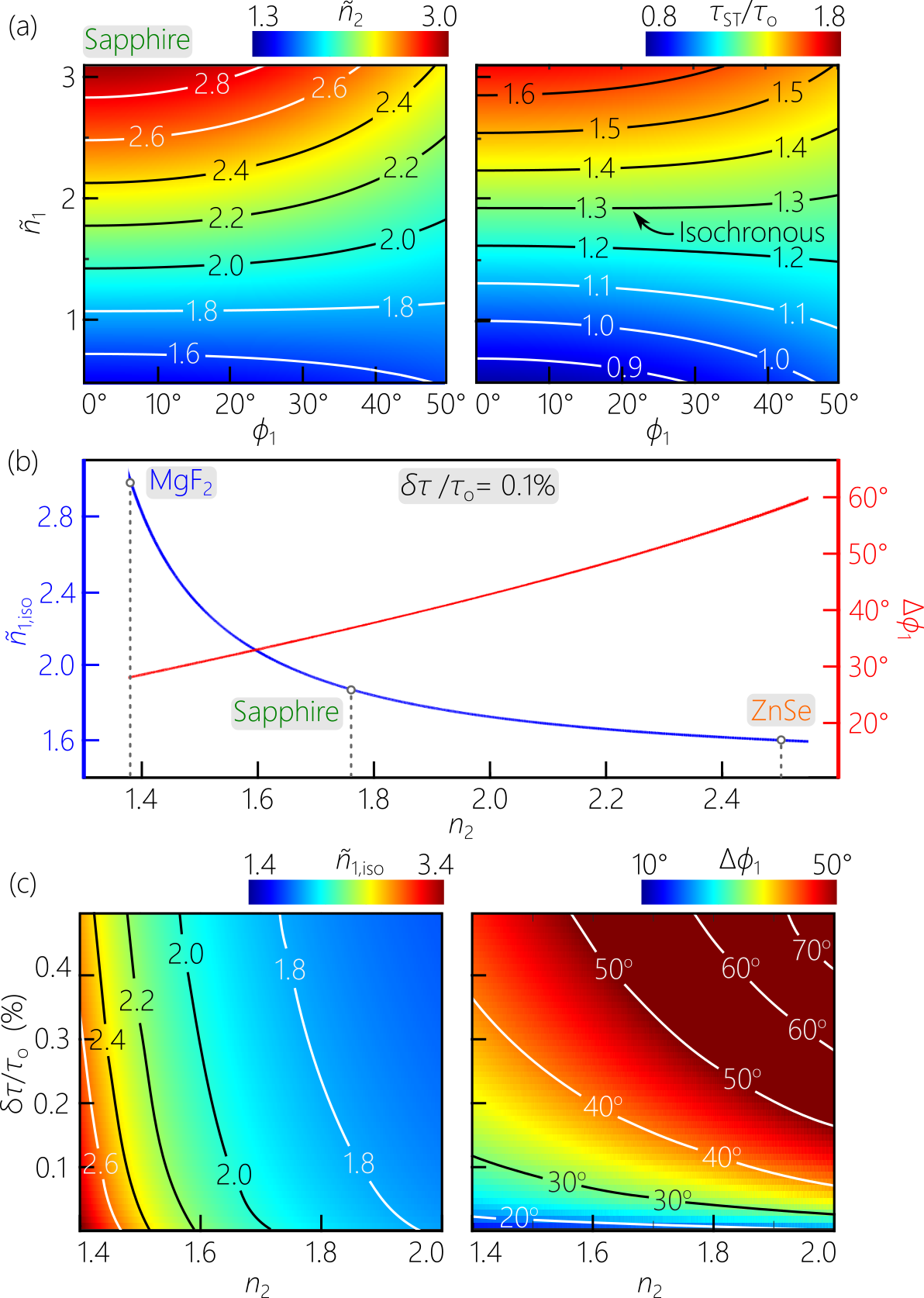
We plot in Fig. 2(a) the group index of the transmitted wave packet traversing a planar interface from free space () to sapphire ( at a wavelength of nm) while varying the group index of the incident wave packet and its incident angle . When (a plane-wave pulse Yessenov et al. (2019b)), independently of as usual, and the group delay increases monotonically with because of the increased path length across the slab. For all other values of , the refracted group index varies with . We require that decrease with to counterbalance the increased path length. It is clear in Fig. 2(a), that this condition occurs when ; i.e., in the subluminal regime. When we plot normalized with respect to in Fig. 2(a), we observe that a flat iso-delay contour occurs at a particular value of . This ST wave packet encounters a constant delay as varies over a broad span.
We plot in Fig. 2(b) the calculated group index for the incident ST wave packet that satisfies the isochronous condition in a medium of index (assuming incidence from free space ). We define this condition as follows: for a given , we calculate the normalized group delay . For each value of , we determine the maximum incident angle that maintains the delay within the range . The group index for the incident wave packet that yields the maximum incident angle within this range for the delay is denoted . We plot the calculated for and the corresponding isochronous angular range . Of course, the value of and depend on the choice of . We plot both and as we vary the delay tolerance in Fig. 2(c) for different materials. It is clear that relaxing the delay tolerance increases the angular range over which the isochronous condition is maintained. Furthermore, relaxing reduces , which approaches . This makes synthesizing the isochronous ST wave packet more convenient Yessenov et al. (2019b).
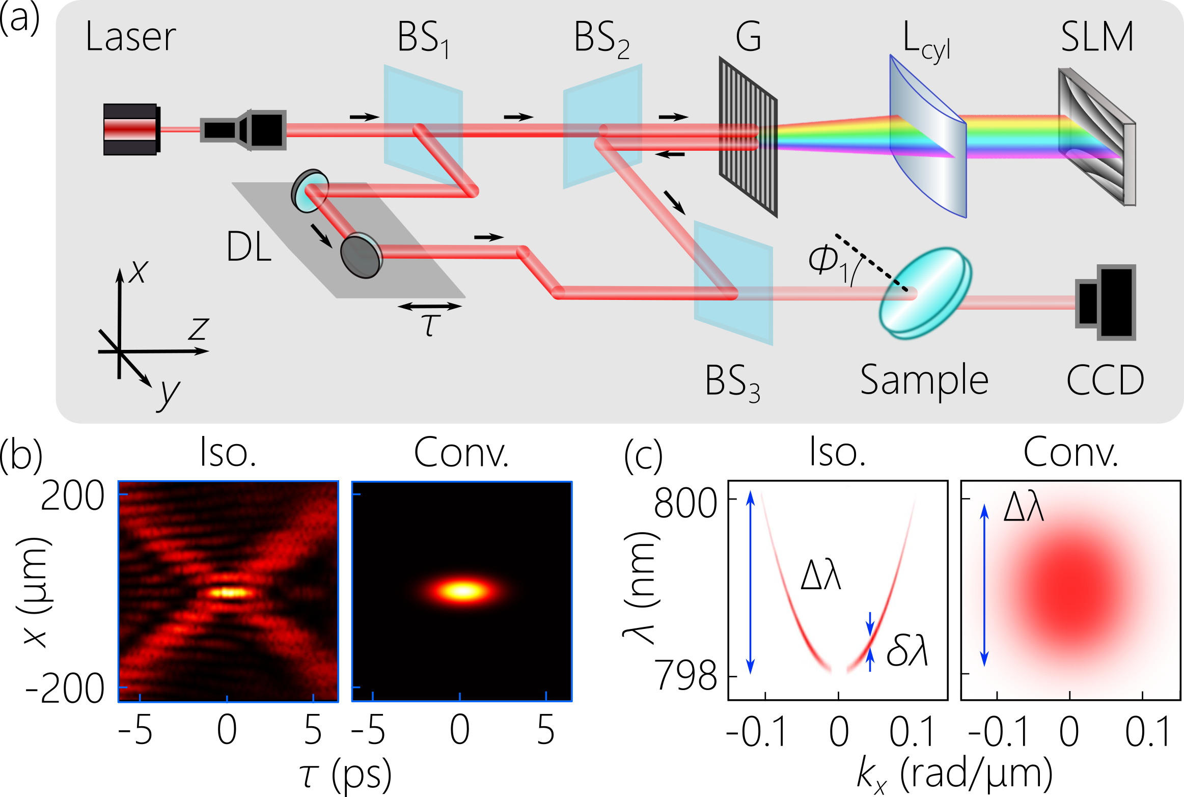
To measure the group delay for planar samples, we make use of the interferometric arrangement in Fig. 3(a), which is based on our previous work in Kondakci and Abouraddy (2019); Bhaduri et al. (2019, 2020). We employ 100-fs pulses from a mode-locked Ti:sapphire laser at a central wavelength of 800 nm directed to a two-path interferometer. In one path, we place the setup for synthesizing the ST wave packets in which the spectrum of the laser pulses is resolved with a diffraction grating (1200 lines/mm), and the first diffraction order is collimated by a cylindrical lens (focal length 50 cm) and directed to a reflective phase-only spatial light modulator (SLM; Hamamatsu X10468-02) that imparts a two-dimensional phase distribution to the spectrally resolved wave front. This phase distribution is designed to assign a specific spatial frequency to each wavelength according to the constraint in Eq. 1. Tuning the spectral tilt angle of the ST wave packet to change its group index is achieved by sculpting the SLM phase Yessenov et al. (2019b). A delay line is placed in the path of the reference arm of the interferometer. The wave packet shaper spectrally filters the initial pulses to a bandwidth of nm, such that the narrower reference pulses are a valid probe to reconstruct the spatio-temporal profile of the ST wave packet by sweeping [Fig. 3(b)]. The group index of the synthesized ST wave packet is verified in two ways. First, the differential group delay between the ST wave packet (traveling at ) and the reference pulse (traveling at ) is measured after placing the detector at two different axial positions, from which we can estimate . Second, we measure the spatio-temporal spectrum in the -plane [Fig. 3(c)] using a combination of grating and Fourier-transforming lens (not shown in the setup for simplicity) Kondakci and Abouraddy (2019).
The isochronous condition is verified in planar samples of MgF2, sapphire, and ZnSe all of thickness mm, which are placed in the common path of the ST wave packet and reference pulse after the interferometer, as shown in Fig. 3(a). Each sample is rotated about the -axis in increments of , resulting in an increase in path length from 5 mm to mm in MgF2, 5.6 mm in sapphire, and 5.25 mm in ZnSe. The group delay is measured for each incident angle , and the results for the three layers are plotted in Fig. 4(b-d). In each case, we plot results for three group indices of the incident ST wave packets: where is independent of over an extended range of incident angles, where increases with as expected, and where anomalously drops with . We compare the results in each case to those for a conventional wave packet (plane-wave pulse) corresponding to () obtained by idling the SLM in Fig. 3(a). The case of ZnSe is particularly striking where the isochronous condition is maintained over the largest span of incident angles despite the changes in the delay with .
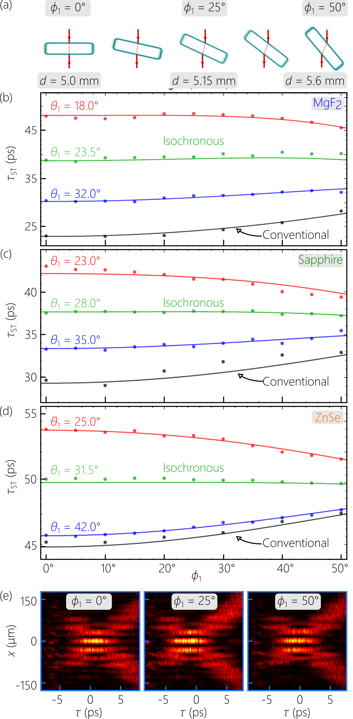
We hypothesized in Bhaduri et al. (2020) that the appropriate ST wave packets can be utilized to blindly synchronize a transmitter with multiple remote receivers at different unknown locations at the same depth beyond an interface between two media. In such a configuration, the sum of the delays in the two media must be invariant with angle of incidence at the interface. Our results here regarding isochronous ST wave packets are a significant step towards such a goal by demonstrating the invariant delay in the second medium (the slab here) with angle of incidence. The maximum distance over which the ST wave packets can be used (the maximum thickness of the slab here) is limited by the so-called ‘spectral uncertainty’ , which is the unavoidable finite bandwidth associated with each spatial frequency Yessenov et al. (2019c). In our experiments here, pm, as determined by the spectral resolution of the grating in Fig. 3(a). The maximum propagation distance exceeds the 5-mm-thickness of the slabs used here. This is confirmed in Fig. 4(e), where only minimal changes are observed in the spatio-temporal profile of the wave packet after traversing the sapphire slab at all values of of interest.
In conclusion, we have demonstrated for the first time, to the best of our knowledge, isochronous optical wave packets: pulsed beams that incur the same group delay after traversing a dielectric slab at any incident angle despite the different path lengths. In our realization, ST wave packets synthesized in free space with a particular group index can satisfy this condition and maintain an invariant group delay over a wide range of incident angles. Isochronous ST wave packets may have applications in clock-synchronization, in free-space optical communications, and in nonlinear optics. Finally, our work here is based on the refraction of propagation-invariant ST wave packet in non-dispersive media. It will be interesting to extend this work to dispersive materials Malaguti et al. (2008); Malaguti and Trillo (2009), and to study the refraction of recently developed ST wave packets that undergo controllable axial evolution, such as accelerating or decelerating wave packets Yessenov and Abouraddy (2020), and those endowed with axial spectral encoding Allende Motz et al. (2020) or group-velocity dispersion in free space Yessenov et al. (2021).
Funding
U.S. Office of Naval Research (ONR) contract N00014-17-1-2458 and ONR MURI contract N00014-20-1-2789.
Disclosures. The authors declare no conflicts of interest.
References
- Sabra (1981) A. I. Sabra, Theories of Light: From Descartes to Newton (Cambridge Univ. Press, 1981).
- Christiaan and Blackwell (1986) C. H. Christiaan and R. J. Blackwell, Christiaan Huygens’ the Pendulum Clock, or, Geometrical Demonstrations Concerning the Motion of Pendula as Applied to Clocks (Iowa State University Press, Ames, 1986).
- Randazzo et al. (2018) J. M. Randazzo, S. A. Ibáñez, and J. M. Rosselló, Am. J. Phys. 86, 518 (2018).
- Kondakci and Abouraddy (2016) H. E. Kondakci and A. F. Abouraddy, Opt. Express 24, 28659 (2016).
- Parker and Alonso (2016) K. J. Parker and M. A. Alonso, Opt. Express 24, 28669 (2016).
- Kondakci and Abouraddy (2017) H. E. Kondakci and A. F. Abouraddy, Nat. Photon. 11, 733 (2017).
- Yessenov et al. (2019a) M. Yessenov, B. Bhaduri, H. E. Kondakci, and A. F. Abouraddy, Opt. Photon. News 30, 34 (2019a).
- Bhaduri et al. (2020) B. Bhaduri, M. Yessenov, and A. F. Abouraddy, Nat. Photon. 14, 416 (2020).
- Donnelly and Ziolkowski (1993) R. Donnelly and R. W. Ziolkowski, Proc. R. Soc. Lond. A 440, 541 (1993).
- Saari and Reivelt (2004) P. Saari and K. Reivelt, Phys. Rev. E 69, 036612 (2004).
- Longhi (2004) S. Longhi, Opt. Express 12, 935 (2004).
- Yessenov et al. (2019b) M. Yessenov, B. Bhaduri, H. E. Kondakci, and A. F. Abouraddy, Phys. Rev. A 99, 023856 (2019b).
- Yessenov et al. (2019c) M. Yessenov, B. Bhaduri, L. Mach, D. Mardani, H. E. Kondakci, M. A. Alonso, G. A. Atia, and A. F. Abouraddy, Opt. Express 27, 12443 (2019c).
- Hall et al. (2021) L. A. Hall, M. Yessenov, and A. F. Abouraddy, arXiv:2101.07317 (2021).
- Kiselev (2007) A. P. Kiselev, Opt. Spectrosc. 102, 603 (2007).
- Turunen and Friberg (2010) J. Turunen and A. T. Friberg, Prog. Opt. 54, 1 (2010).
- Hernández-Figueroa et al. (2014) H. E. Hernández-Figueroa, E. Recami, and M. Zamboni-Rached, eds., Non-diffracting Waves (Wiley-VCH, 2014).
- Salo and Salomaa (2001) J. Salo and M. M. Salomaa, J. Opt. A 3, 366 (2001).
- Kondakci and Abouraddy (2019) H. E. Kondakci and A. F. Abouraddy, Nat. Commun. 10, 929 (2019).
- Bhaduri et al. (2019) B. Bhaduri, M. Yessenov, and A. F. Abouraddy, Optica 6, 139 (2019).
- Porras (2017) M. A. Porras, Opt. Lett. 42, 4679 (2017).
- Efremidis (2017) N. K. Efremidis, Opt. Lett. 42, 5038 (2017).
- Wong and Kaminer (2017) L. J. Wong and I. Kaminer, ACS Photon. 4, 2257 (2017).
- Malaguti et al. (2008) S. Malaguti, G. Bellanca, and S. Trillo, Opt. Lett. 33, 1117 (2008).
- Malaguti and Trillo (2009) S. Malaguti and S. Trillo, Phys. Rev. A 79, 063803 (2009).
- Yessenov and Abouraddy (2020) M. Yessenov and A. F. Abouraddy, Phys. Rev. Lett. 125, 233901 (2020).
- Allende Motz et al. (2020) A. M. Allende Motz, M. Yessenov, and A. F. Abouraddy, arXiv:2010.10719 (2020).
- Yessenov et al. (2021) M. Yessenov, L. A. Hall, and A. F. Abouraddy, arXiv:2102.09443 (2021).