GAROTA: Generalized Active Root-Of-Trust Architecture
Abstract
Embedded (aka smart or IoT) devices are increasingly popular and becoming ubiquitous. Unsurprisingly, they are also attractive attack targets for exploits and malware. Low-end embedded devices, designed with strict cost, size, and energy limitations, are especially challenging to secure, given their lack of resources to implement sophisticated security services, available on higher-end computing devices. To this end, several tiny Roots-of-Trust (RoTs) were proposed to enable services, such as remote verification of device’s software state and run-time integrity. Such RoTs operate reactively: they can prove whether a desired action (e.g., software update, or execution of a program) was performed on a specific device. However, they can not guarantee that a desired action will be performed, since malware controlling the device can trivially block access to the RoT by ignoring/discarding received commands and other trigger events. This is a major and important problem because it allows malware to effectively “brick” or incapacitate a potentially huge number of (possibly mission-critical) devices.
Though recent work made progress in terms of incorporating more active behavior atop existing RoTs, it relies on extensive hardware support –Trusted Execution Environments (TEEs) which are too costly for low-end devices. In this paper, we set out to systematically design a minimal active RoT for tiny low-end MCU-s. We begin with the following questions: (1) What functions and hardware support are required to guarantee actions in the presence of malware?, (2) How to implement this efficiently?, and (3) What security benefits stem from such an active RoT architecture? We then design, implement, formally verify, and evaluate GAROTA : Generalized Active Root-Of-Trust Architecture. We believe that GAROTA is the first clean-slate design of an active RoT for low-end MCU-s. We show how GAROTA guarantees that even a fully software-compromised low-end MCU performs a desired action. We demonstrate its practicality by implementing GAROTA in the context of three types of applications where actions are triggered by: sensing hardware, network events and timers. We also formally specify and verify GAROTA functionality and properties.
1 Introduction
The importance of embedded systems is hard to overestimate and their use in critical settings is projected to rise sharply [1]. Such systems are increasingly inter-dependent and used in many settings, including household, office, factory, automotive, health and safety, as well as national defense and space exploration. Embedded devices are usually deployed in large quantities and for specific purposes. Due to cost, size and energy constraints, they typically cannot host complex security mechanisms. Thus, they are an easy and natural target for attackers that want to quickly and efficiently cause harm on an organizational, regional, national or even global, level. Fundamental trade-offs between security and other priorities, such as cost or performance are a recurring theme in the domain of embedded devices. Resolving these trade-offs, is challenging and very important.
Numerous architectures focused on securing low-end micro-controller units (MCU-s) by designing small and affordable trust anchors [2]. However, most such techniques operate passively. They can prove, to a trusted party, that certain property (or action) is satisfied (or was performed) by a remote and potentially compromised low-end MCU. Examples of such services include remote attestation [21, 37, 14, 5, 9, 31], proofs of remote software execution [16], control-flow & data-flow attestation [17, 3, 18, 49, 46, 39], as well as proofs of remote software update, memory erasure, and system-wide reset[15, 4, 8]. These architectures are typically designed to provide proofs that are unforgeable, despite potential compromise of the MCU.
Aforementioned approaches are passive in nature. While they can detect integrity violations of remote devices, they cannot guarantee that a given security or safety-critical task will be performed. For example, consider a network comprised of a large number (of several types of) simple IoT devices, e.g., an industrial control system. Upon detecting a large-scale compromise, a trusted remote controller wants to fix the situation by requiring all compromised devices to reset, erase, or update themselves in order to expunge malware. Even if each device has an uncompromised, yet passive, RoT, malware (which is in full control of the device’s software state) can easily intercept, ignore, or discard any requests for the RoT, thus preventing its functionality from being triggered. Therefore, the only way to repair these compromised devices requires direct physical access (i.e, reprogramming by a human) to each device. Beyond the DoS damage caused by the multitude of essentially “bricked” devices, physical reprogramming itself is slow and disruptive, i.e., a logistical nightmare.
Motivated by the above, recent research [48, 27] yielded trust anchors that exhibit a more active behavior. Xu et al. [48] propose the concept of Authenticated Watch-Dog Timers (WDT), which can enforce periodic execution of a secure component (an RoT task), unless explicit authorization (which can itself include a set of tasks) is received from a trusted controller. In [27] this concept is realized with the reliance on an existing passive RoT (ARM TrustZone), as opposed to a dedicated co-processor as in the original approach from [48]. Both techniques are time-based, periodically and actively triggering RoT invocation, despite potential compromise of the host device. (We discuss them in more detail in Section 5.4.)
In this paper, we take the next step and design a more general active RoT, called GAROTA: Generalized Active Root-Of-Trust Architecture. Our goal is an architecture capable of triggering guaranteed execution of trusted and safety-critical tasks based on arbitrary events captured by hardware peripherals (e.g., timers, GPIO ports, and network interfaces) of an MCU the software state of which may be currently compromised. In principle, any hardware event that causes an interruption on the unmodified MCU can trigger guaranteed execution of trusted software in GAROTA (assuming proper configuration). In that vein, our work can be viewed as a generalization of concepts proposed in [48, 27], enabling arbitrary events (interruption signals, as opposed to the timer-based approach from prior work) to trigger guaranteed execution of trusted functionalities. In comparison, prior work has the advantage of relying on pre-existent hardware, thus not requiring any hardware changes. On the other hand, our clean-slate approach, based on a minimal hardware design, enables new applications and is applicable to lower-end resource-constrained MCU-s.
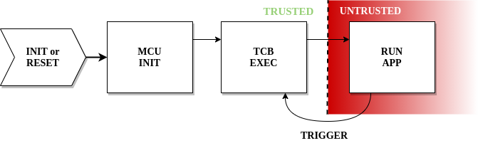
At a high level, GAROTA is based on two main notions: “Guaranteed Triggering” and “Re-Triggering on Failure”. The term is used to refer to an event that causes GAROTA RoT to take over the execution in the MCU. The “guaranteed triggering” property ensures that a particular event of interest always triggers execution of GAROTA RoT. Whereas,“re-triggering on failure” assures that, if RoT execution is illegally interrupted for any reason (e.g., attempts to violate execution’s integrity, power faults, or resets), the MCU resets and the RoT is guaranteed to be the first to execute after subsequent re-initialization. Figure 1 illustrates this workflow.
We use GAROTA to address three realistic and compelling use-cases for the active RoT:
-
•
GPIO-TCB: A safety-critical sensor/actuator hybrid, which is guaranteed to sound an alarm if the sensed quantity (e.g., temperature, CO2 level, etc) exceeds a certain threshold. This use-case exemplifies hardware-based triggering.
- •
-
•
NetTCB: a trusted component that is always guaranteed to process commands received over the network, thus preventing malware in the MCU from intercepting and/or discarding commands destined for the RoT. This use-case exemplifies network-based triggering.
In all three cases, the guarantees hold despite potential full compromise of the MCU software state, as long as the RoT itself is trusted.
In addition to designing and instantiating GAROTA with three use-cases, we formally specify GAROTA goals and requirements using Linear Temporal Logic (LTL). These formal specifications offer precise definitions for the security offered by GAROTA and its corresponding assumptions expected from the underlying MCU, i.e., its machine model. This can serve as an unambiguous reference for future implementations and for other derived services. Finally, we use formal verification to prove that the implementation of GAROTA hardware modules adheres to a set of sub-properties (also specified in LTL) that – when composed with the MCU machine model – are sufficient to achieve GAROTA end-to-end goals. In doing so, we follow a similar verification approach that has been successfully applied in the context of passive RoT-s [14, 16, 38].
We implement and evaluate GAROTA and make its verified implementation (atop the popular low-end MCU TI MSP430) along with respective computer proofs/formal verification publicly available in [6].
2 Scope
This work focuses on low-end embedded MCU-s and on design with minimal hardware requirements. A minimal design simplifies reasoning about GAROTA and formally verifying its security properties. In terms of practicality and applicability, we believe that an architecture that is cost-effective enough for the lowest-end MCU-s can also be adapted (and potentially enriched) for implementations on higher-end devices with higher hardware budgets, while the other direction is usually more challenging. Thus, our design is applicable to the smallest and weakest devices based on low-power single-core platform with only a few KBytes of program and data memory (such as the aforementioned Atmel AVR ATmega and TI MSP430), with - and -bit CPUs, typically running at - MHz clock frequencies, with KBytes of addressable memory. SRAM is used as data memory ranging in size between and KBytes, while the rest of address space is available for program memory. Such devices usually run software atop “bare metal”, execute instructions in place (physically from program memory), and have no memory management unit (MMU) to support virtual memory.
Our initial choice of implementing GAROTA atop the well-known TI MSP430 low-energy MCU is motivated by availability of a well-maintained open-source MSP430 hardware design from OpenCores [25]. Nevertheless, our design and its machine model are applicable to other low-end MCU-s of the same class.
3 GAROTA Overview
The goal of GAROTA is to guarantee eventual execution of a pre-defined functionality implemented as a trusted software executable. We refer to this executable as GAROTA trusted computing base (TCB). GAROTA is agnostic to the particular functionality implemented by , which allows guaranteed execution of arbitrary tasks, to be determined based on the application domain; see Section 5 for examples.
A refers to a particular event that can be configured to cause the TCB to execute. Examples of possible triggers include hardware events from:
-
•
External (usually analog) inputs, e.g., detection of a button press, motion, sound or certain temperature/CO2 threshold.
-
•
Expiring timers, i.e., a periodic .
-
•
Arrival of a packet from the network, e.g., carrying a request to collect sensed data, perform sensing/actuation, or initiate a security task, such as code update or remote attestation.
If configured correctly, these events cause interruptions, which are used by GAROTA to guarantee execution of . Since and TCB implementation are configurable, we assume that these initial configurations are done securely, at or before initial deployment. configuration will include the types of interruptions and respective settings e.g., which GPIO port, what type of event, its time granularity, etc. At runtime, GAROTA protects the initial configuration from illegal modifications, i.e., ensures correct behavior. This protection includes preserving interrupt configuration registers, interrupt handlers, and interrupt vectors. This way GAROTA guarantees that always results in an invocation of the TCB.
However, guaranteed invocation of the TCB upon occurrence of a is not sufficient to claim that is properly performed, since the TCB code (and execution thereof) could itself be tampered with. To this end, GAROTA provides runtime protections that prevent any unprivileged/untrusted program from modifying the TCB code, i.e., the program memory region reserved for storing that code. (Recall that instructions execute in place, from program memory). GAROTA also monitors the execution of the TCB code to ensure that:
-
1.
Atomicity: Execution is atomic (i.e., uninterrupted), from the TCB’s first instruction (legal entry), to its last instruction (legal exit);
-
2.
Non-malleability: During execution, cannot be modified, other than by the TCB code itself, e.g., no modifications by other software or DMA controllers.
These two properties ensure that any potential malware residing on the MCU (i.e., compromised software outside TCB or compromised DMA controllers) cannot tamper with TCB execution.
GAROTA monitors TCB execution and, if a violation of any property (not just atomicity and non-malleability) occurs, it triggers an immediate MCU reset to a default trusted state where TCB code is the first component to execute. Therefore, any attempt to interfere with the TCB functionality or execution only causes the TCB to recover and re-execute, this time with the guarantee that unprivileged/untrusted applications cannot interfere.
Both configurations and the TCB implementation are updatable at run-time, as long as the updates are performed from within the TCB itself. While this feature is not strictly required for security, we believe it provides flexibility/updatability, while ensuring that untrusted software is still unable to modify GAROTA trusted components and configuration thereof. In Section 4.7, we also discuss how GAROTA can enforce TCB confidentiality, which is applicable to cases where implements cryptographic or privacy sensitive tasks.
Each sub-property in GAROTA is implemented, and individually optimized, as a separate GAROTA sub-module. These sub-modules are then composed and shown secure (when applied to the MCU machine model) using a combination of model-checking-based formal verification and an LTL computer-checked proof. GAROTA modular design enables verifiability and minimality, resulting in low hardware overhead and significantly higher confidence about the security provided by its design and implementation.
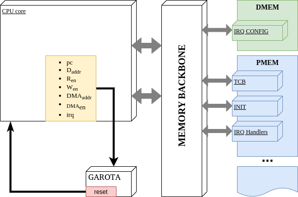
As shown in Figure 2, GAROTA is implemented as a hardware component that monitors a set o CPU signals to detect violations to required security properties. As such it does not interfere with the CPU core implementation, e.g., by modifying its behavior or instruction set. In subsequent sections we describe these properties in more detail and discuss their implementation and verification. Finally, we use a commodity FPGA to implement GAROTA atop the low-end MCU MSP430 and report on its overhead.
4 GAROTA in Detail
We now get into the details of GAROTA. The next section provides some background on LTL and formal verification; given some familiarity with these notions, it can be skipped without loss of continuity.
4.1 LTL & Verification Approach
Formal Verification refers to the computer-aided process of proving that a system (e.g., hardware, software, or protocol) adheres to its well-specified goals. Thus, it assures that the system does not exhibit any unintended behavior, especially, in corner cases (rarely encountered conditions and/or execution paths) that humans tend to overlook.
To verify GAROTA, we use a combination of Model Checking and Theorem Proving, summarized next. In Model Checking, designs are specified in a formal computation model (e.g., as Finite State Machines or FSMs) and verified to adhere to formal logic specifications. The proof is performed through automated and exhaustive enumeration of all possible system states. If the desired specification is found not to hold for specific states (or transitions among them), a trace of the model that leads to the erroneous state is provided, and the implementation can then be fixed accordingly. As a consequence of exhaustive enumeration, proofs for complex systems that involve complex properties often do not scale well due to so-called “state explosion”.
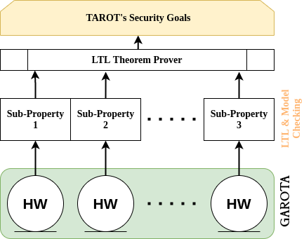
To cope with that problem, our verification approach (in line with prior work [14, 16]) is to specify each sub-property in GAROTA using Linear Temporal Logic (LTL) and verify each respective sub-module for compliance. In this process, our verification pipeline automatically converts digital hardware, described at Register Transfer Level (RTL) using Verilog, to Symbolic Model Verifier (SMV) [36] FSMs using Verilog2SMV [29]. The SMV representation is then fed to the well-known NuSMV [12] model-checker for verification against the specified LTL sub-properties. Finally, the composition of the LTL sub-properties (verified in the model-checking phase) is proven to achieve GAROTA end-to-end goals using an LTL theorem prover [19]. Our verification strategy is depicted in Figure 3.
Regular propositional logic includes propositional connectives, such as: conjunction , disjunction , negation , and implication . LTL augments it with temporal quantifiers, thus enabling sequential reasoning. In this paper, we are interested in the following temporal quantifiers:
-
•
X – neXt : holds if is true at the next system state.
-
•
F – Future : holds if there exists a future state where is true.
-
•
G – Globally : holds if for all future states is true.
-
•
U – Until : holds if there is a future state where holds and holds for all states prior to that.
-
•
W – Weak until : holds if, assuming a future state where holds, holds for all states prior to that. If never becomes true, must hold forever. Or, more formally:
Note that, since GAROTA TCB is programmable and its code depends on the exact functionality for each application domain, verification and correctness of any specific TCB code is not within our goals. We assume that the user is responsible for assuring correctness of the trusted code to be loaded atop GAROTA active RoT. This assumption is consistent with other programmable (though passive) RoTs, including those targeting higher-end devices, such as Intel SGX [28], and ARM TrustZone[7]. In many cases, we expect the TCB code to be minimal (see examples in Section 5), and thus unlikely to have bugs.
4.2 Notation, Machine Model, & Assumptions
This section discusses our machine and adversarial models. We start by overviewing them informally in Sections 4.2.1, 4.2.2 and 4.2.3). Then, Section 4.2.5, formalizes the machine model using LTL. For quick-reference, Table 1 summarizes the notation used in the rest of the paper.
| Current Program Counter value | |
| Signal that indicates if the MCU is reading from memory (1-bit) | |
| Signal that indicates if the MCU is writing to memory (1-bit) | |
| Address for an MCU memory access (read or write) | |
| Signal that indicates if DMA is currently enabled (1-bit) | |
| Memory address being accessed by DMA, if any | |
| Global Interrupt Enable: signal that indicates whether or not interrupts are globally enabled (1-bit). | |
| Signal that indicates if an interrupt is happening | |
| Region corresponding to the entire data memory of the MCU: . | |
| Region corresponding to the entire program memory of the MCU: . | |
| Memory region reserved for the TCB’s executable implementing : . . | |
| Memory region containing the MCU’s default initialization code. : . . | |
| A 1-bit signal that reboots/resets the MCU when set to logical |
4.2.1 CPU Hardware Signals
GAROTA neither modifies nor verifies the underlying CPU core/instruction set. It is assumed that the underlying CPU adheres to its specification and GAROTA is implemented as a standalone hardware module that runs in parallel with the CPU, and enforcing necessary guarantees in hardware. The following CPU signals are relevant to GAROTA:
H1 – Program Counter (PC): always contains the address of the instruction being executed in the current CPU cycle.
H2 – Memory Address: Whenever memory is read or written by the CPU, the data-address signal () contains the address of the corresponding memory location. For a read access, a data read-enable bit () must be set, while, for a write access, a data write-enable bit () must be set.
H3 – DMA: Whenever a DMA controller attempts to access the main system memory, a DMA-address signal () reflects the address of the memory location being accessed and a DMA-enable bit () must be set. DMA can not access memory when is off (logical zero).
H4 – MCU Reset: At the end of a successful reset routine, all registers (including ) are set to zero before resuming normal software execution flow. Resets are handled by the MCU in hardware. Thus, the reset handling routine can not be modified. Once execution re-starts, PC is set to point to the first instruction in the boot section of program memory, referred to as (see M2 below). When a reset happens, the corresponding signal is set. The same signal is also set when the MCU initializes for the first time. An MCU also resets its DMA controller, and any prior configuration thereof. (DMA) behavior is configured by user software at runtime. By default (i.e., after a reset) DMA is inactive.
H5 – Interrupts: Whenever an interrupt occurs, the corresponding signal is set. Interrupts may be globally enabled or disabled in software. The 1-bit signal always reflects whether or not they are currently enabled. The default state (i.e., at boot or after a reset) is disabled (logical zero).
4.2.2 Memory: Layout & Initial Configuration
As far as MCU initial memory layout and its initial software configuration (set at, or prior to, its deployment), the following are relevant to GAROTA:
M1 – PMEM: Corresponds to the entire address space. Instructions are executed in place. Hence, at runtime, points to the address storing the instruction being executed.
M2 – INIT: Section of containing the MCU boot segment, i.e., the first software to be executed whenever the MCU boots or after a . We assume code is finite.
M3 – TCB: Section of reserved for GAROTA trusted code, i.e., . TCB is located immediately after ; it is the first software to execute following successful completion of .
M4 – IRQ-Table and Handlers: IRQ-Table is located in and contains pointers to the addresses of so-called interrupt handlers. When an interrupt occurs, the MCU hardware causes a jump to the corresponding handler routine. The address of this routine is specified by the IRQ-Table fixed index corresponding to that particular interrupt. Handler routines are code segments (functions) also stored in .
M5 – : Set of registers in used to configure specific behavior of individual interrupts at runtime, e.g., deadline of a timer-based interrupt, or type of event on a hardware-based interrupt.
Note that the initial memory configuration can be changed at run-time (e.g., by malware that infects the device,as discussed in Section 4.2.4), unless it is explicitly protected by GAROTA verified hardware modules.
4.2.3 Initial Trigger Configuration
T1 – : GAROTA is configured, at MCU (pre)deployment-time, by setting the corresponding entry in IRQ-Table and respective handler to jump to the first instruction in TCB () and by configuring the registers in with desired interrupt parameters, reflecting the desired behavior; see Section 5 for examples. Thus, a event causes the TCB code to execute, as long as the initial configuration is maintained.
Our initial configuration is not much different from a regular interrupt configuration in a typical embedded system program. It must correctly point to GAROTA TCB legal entry point, just as regular interrupts must correctly point to their respective handler entry points. For example, to initially configure a timer-based trigger, the address in IRQ-Table corresponding to the respective hardware timer is set to point to and the correspondent registers in are set to define the desired interrupt period.
4.2.4 Adversarial Model
We consider an adversary that controls ’s entire software state, including code, and data. can read/write from/to any memory that is not explicitly protected by hardware-enforced access control rules. might also have full control over all Direct Memory Access (DMA) controllers of . Recall that DMA allows a hardware controller to directly access main memory ( or ) without going through the CPU.
Physical Attacks: physical and hardware-focused attacks are out of scope of GAROTA. Specifically, we assume that can not modify induce hardware faults, or interfere with GAROTA via physical presence attacks and/or side-channels. Protection against such attacks is an orthogonal issue, which can be addressed via physical security techniques [41].
Network DoS Attacks: we also consider out-of-scope all network DoS attacks whereby drops traffic to/from , or floods with traffic, or simply jams communication. Note that this assumption is relevant only to network-triggered events, exemplified by the NetTCB instantiation of GAROTA, described in Section 5.3.
Correctness of TCB’s Executable: we stress that the purpose of GAROTA is guaranteed execution of , as specified by the application developer and loaded onto GAROTA TCB at deployment time. Similar to existing RoTs (e.g., TEE-s in higher-end CPUs) GAROTA does not check correctness of, and absence of implementation bugs in, ’s implementation. In many applications, code is minimal; see examples in Section 5. Moreover, correctness of need not be assured. Since embedded applications are originally developed on more powerful devices (e.g., general-purpose computers), various vulnerability detection methods, e.g., fuzzing [11], static analysis [13], or formal verification, can be employed to avoid or detect implementation bugs in . All that can be performed off-line before loading onto GAROTA TCB and the entire issue is orthogonal to GAROTA functionality.
4.2.5 Machine Model (Formally)
Definition 1.
Machine Model:Memory Modifications: (1) Successful Trigger Modification: (2) Successful Interrupt Disablement: (3) Trigger/TCB Initialization (4 & 5): (4) (5)
Based on the high-level properties discussed earlier in this section, we now formalize the subset (relevant to GAROTA) of the MCU machine model using LTL. Figure 4 presents our machine model as a set of LTL statements.
LTL statement (1) models the fact that modifications to a given memory address () can be done either via the CPU or DMA. Modifications by the CPU imply setting and . If is a memory region, rather than a single address, we denoted that a modification happened within the particular region by saying that , instead. Conversely, DMA modifications to region require and . This models the MCU behaviors stated informally in H2 and H3.
In accordance with M4 and M5, a successful modification to a pre-configured implies changing interrupt tables, interrupt handlers, or interrupt configuration registers (ICR-s). Since, per M4, the first two are located in , modifying them means writing to . The ICR is located in a location denoted . Therefore, the LTL statement (2) models a successful misconfiguration of as requiring a memory modification either within or within , without causing an immediate system-wide reset (). This is because an immediate reset prevents the modification attempt from taking effect (see H4).
LTL (3) models that attempts to disable interrupts are reflected by CPU signal (per H5). In order to successfully disable interrupts, must be able to switch interrupts from enabled () to disabled ( – disabled in the following cycle), without causing an MCU .
Recall that (from H1) reflects the address of the instruction currently executing. implies that GAROTA TCB is currently executing. LTL (4) models T1. As long as the initial proper configuration of is never modifiable by untrusted software () and that untrusted software can never globally disable interrupts (), a would always cause TCB execution (). Recall that we assume that the TCB may update – though not misconfigure – behavior, since the TCB is trusted. Similarly, LTL 5 states that, as long as is never modified by untrusted software, a will always trigger TCB execution (per H4, M2, and M3).
This concludes our formal model of the default behavior of low-end MCU-s considered in this work.
4.3 GAROTA End-To-End Goals Formally
Definition 2.
Guaranteed Trigger:Definition 3.
Re-Trigger on Failure:Using the notation from Section 4.2, we proceed with the formal specification of GAROTA end-goals in LTL. Definition 2 specifies the “guaranteed trigger” property. It states in LTL that, whenever a occurs, a TCB execution/invocation (starting at the legal entry point) will follow.
While Definition 2 guarantees that a particular interrupt of interest () will cause the TCB execution, it does not guarantee proper execution of the TCB code as a whole. The “re-trigger on failure” property (per Definition 3) stipulates that, whenever TCB starts execution (i.e., ), it must execute without interrupts or DMA interference 111Since DMA could tamper with intermediate state/results in ., i.e., . This condition must hold until:
-
1.
: the legal exit of TCB is reached, i.e., execution concluded successfully.
-
2.
: another TCB execution (from scratch) has been triggered to occur.
In other words, this specification reflects a cyclic requirement: either the security properties of the TCB proper execution are not violated, or TCB execution will re-start later.
Note that we use the quantifier Weak Until (W) instead regular Until (U), because, for some embedded applications, the TCB code may execute indefinitely; see Section 5.1 for one such example.
4.4 GAROTA Sub-Properties
Definition 4.
LTL Sub-Properties implemented and enforced by GAROTA.Trusted Updates: (6) IRQ Configuration Protection: (7) Interrupt Disablement Protection: (8) TCB Execution Protection: (9) (10) (11)
Based on our machine model and GAROTA end goals, we now postulate a set of necessary sub-properties to be implemented by GAROTA. Next, Section 4.5 shows that this minimal set of sub-properties suffices to achieve GAROTA end-to-end goals with a computer-checked proof. LTL specifications of the sub-properties are presented in Figure 6.
GAROTA enforces that only trusted updates are allowed to . GAROTA hardware issues a system-wide MCU upon detecting any attempt to modify at runtime, unless this modification comes from the execution of the TCB code itself. This property is formalized in LTL (6). It prevents any untrusted application software from misconfiguring IRQ-Table and interrupt handlers, as well as from modifying the segment and the TCB code itself, because these sections are located within . As a side benefit, it also prevents attacks that attempt to physically wear off Flash (usually used to implement in low-end devices) by excessively and repeatedly overwriting it at runtime. Similarly, GAROTA prevents untrusted components from modifying – registers controlling the configuration. This is specified by LTL 7.
LTL 8 enforces that interrupts can not be globally disabled by untrusted applications. Since, each is based on interrupts, disablement of all interrupts would allow untrusted software to disable the itself, and thus the active behavior of GAROTA. This requirement is specified by checking the relation between current and next values of , using the LTL neXt operator. In order to switch from logical (current cycle) to (next cycle), TCB must be executing when becomes (X()), or the MCU will .
In order to assure that the TCB code is invoked and executed properly, GAROTA hardware implements LTL-s (9), (10), and (11). LTL 9 enforces that the only way for ’s execution to terminate, without causing a , is through its last instruction (its only legal exit): . This is specified by checking the relation between current and next values using LTL neXt operator. If the current value is within , and next value is outside , then either current value must be the address of , or is set to in the next cycle. Similarly, LTL 10 enforces that the only way for to enter is through the very first instruction: . This prevents execution from starting at some point in the middle of , thus making sure that always executes in its entirety. Finally, LTL 11 enforces that is always set if interrupts or DMA modifications happen during ’s execution. Even though LTLs 9 and 10 already enforce that PC can not change to anywhere outside , interrupts could be programmed to return to an arbitrary instruction within the . Or, DMA could change values currently in use by TCB. Both of these events can alter TCB behavior and are treated as violations.
4.5 GAROTA Composition Proof
Theorem 1.
.Theorem 2.
.The complete computer-checked proofs (using Spot2.0 [19]) of Theorems 1 and 2 are publicly available at [6]. Below we present the intuition behind them.
Proof of Theorem 1 (Intuition).
From machine model’s LTL (4), as long as the (1) initial trigger configuration is never modified from outside the ; and (2) interrupts are never disabled from outside the ; it follows that a will cause a proper invocation of the TCB code. Also, successful modifications to the ’s configuration imply writing to or without causing a (per LTL (2)). Since GAROTA verified implementation guarantees that memory modifications (specified in LTL (1)) to (LTL (6)) or (LTL (7)) always cause a , illegal modifications to are never successful. Finally, LTL (8) assures that any illegal interrupt disablement always causes a , and is thus never successful). Therefore, GAROTA satisfies all necessary conditions to guarantee the goal in Definition 2. ∎
Proof of Theorem 2 (Intuition).
The fact that a reset always causes a later call to the TCB follows from the machine model’s LTL (5) and GAROTA guarantee in LTL (6). LTLs (9) and (9) ensure that the TCB executable is properly invoked and executes atomically, until its legal exit. Otherwise a flag is set, which (from the above argument) implies a new call to TCB. Finally, LTL 11 assures that any interrupt or DMA activity during TCB execution will cause a , thus triggering a future TCB call and satisfying Definition 3. ∎
See [6] for the formal computer-checked proofs.
4.6 Sub-Module Implementation+Verification
Following the sufficiency proof in Section 4.5 for sub-properties in Definition 4, we proceed with the implementation and formal verification of GAROTA hardware using the NuSMV model-checker (see Section 4.1 for details).
GAROTA modules are implemented as Mealy FSMs (where outputs change with the current state and current inputs) in Verilog. Each FSM has one output: a local . GAROTA output is given by the disjunction (logic or) of local -s of all sub-modules. Thus, a violation detected by any sub-module causes GAROTA to trigger an immediate MCU . For the sake of easy presentation we do not explicitly represent the value of in the figures. Instead, we define the following implicit representation:
-
1.
output is 1 whenever an FSM transitions to the state (represented in red color);
-
2.
output remains 1 until a transition leaving the state is triggered;
-
3.
output is 0 in all other states (represented in blue color).
Note that all FSM-s remain in the state until , which signals that the MCU reset routine finished.
Figure 7 illustrates GAROTA sub-module responsible for assuring that modifications are only allowed from within the TCB. This minimal 2-state machine works by monitoring , , , , and to detect illegal modification attempts by switching from to state, upon detection of any such action. It is verified to adhere to LTL (6). A similar FSM is used to verifiably enforce LTL (7), with the only distinction of checking for writes within region instead, i.e., and . We omit the illustration of this FSM to conserve space, due to page limits.
Figure 8 presents an FSM implementing LTL 8. It monitors the “global interrupt enable” () signal to detect attempts to illegally disable interrupts. It consists of three states: (1) , representing execution periods where ; (2) , for cases where , and (3) . To switch between and states, this FSM requires , thus preventing misconfiguration by untrusted software.
Finally, the FSM in Figure 9 verifiably implements LTL-s 9, 10, and 11. This FSM has 5 states, one of which is . Two basic states correspond to whenever: the TCB is executing (state “”), and not executing (state “”). From the only reachable path to is through state , which requires – TCB only legal entry point. Similarly, from the only reachable path to is through state , which requires – TCB only legal exit. Also, in all states where (including entry and exit transitions) this FSM requires DMA and interrupts to remain inactive. Any violation of these requirements, in any of the four regular states, causes the FSM transition to , thus enforcing TCB execution protection.
4.7 TCB Confidentiality
One instance of GAROTA enables confidentiality of TCB data and code with respect to untrusted applications. This is of particular interest when implements cryptographic functions or privacy-sensitive tasks.
This goal can be achieved by including and epilogue phase in the TCB executable, with the goal of performing a cleanup, erasing all traces of the TCB execution from the stack and heap. While the TCB execution may be interrupted before the execution of the epilogue phase, such an interruption will cause an MCU . The Re-Trigger on Failure property assures that TCB code will execute (as a whole) after any and will thus erase remaining execution traces from before subsequent execution of untrusted applications. In a similar vein, if confidentiality of the executable is desirable, it can be implemented following LTL (12), which formalizes read attempts based on signal:
| (12) | ||||
An FSM implementing this property is shown in Figure 10. Note that, despite visual similarity with the FSM in Figure 7, the confidentiality FSM checks for reads (instead of writes) to the TCB (instead of entire ).
This property prevents external reads to the TCB executable by monitoring , , and DMA. When combined with the aforementioned erasure epilogue, it also enables secure storage of cryptographic secrets within the TCB binary (as in architectures such as [4, 5, 20]). This part of GAROTA design is optional, since some embedded applications do not require confidentiality, e.g., those discussed in Sections 5.1 and 5.2.
4.8 Resets & Availability
One important remaining issue is availability. For example, malware might interrupt (or tamper with) with execution after a preventing the subsequent execution of TCB. Also, malware could to interrupt the TCB execution, after each re-, with the goal of resetting the MCU indefinitely, and thereby preventing TCB execution from ever completing its task.
We observe that such actions are not possible, since they would require either DMA activity or interrupts to: (1) hijack control-flow; or (2) abuse GAROTA to successively the MCU during TCB execution after each re-trigger. Given H5 interrupts are disabled by default at boot time. Additionally, H4 states that any prior DMA configuration is cleared to the default disabled state after a . Hence, and the first execution of TCB after a cannot be interrupted or tampered with by DMA.
Finally, we note that, despite preventing security violations by (and implementing re-trigger based on) resetting the MCU, GAROTA does not provide any advantage to malware that aims to simply disrupt execution of (non-TCB) applications by causing . Any software running on bare metal (including malware) can always intentionally reset the MCU. Resets are the default mechanism to recover from regular software faults on unmodified (off-the-shelf) low-end MCU-s, regardless of GAROTA.
5 Sample Applications
Many low-end MCU use-cases and applications can benefit from -based active RoTs. To demonstrate generality of GAROTA, we prototyped three concrete examples, each with a different type of -s. This section overviews these examples: (1) GPIO-TCB uses external analog events (Section 5.1), TimerTCB uses timers (Section 5.2), and NetTCB uses network events (Section 5.3). Finally, Section 5.4 discusses how GAROTA can match active security services proposed in [48] and [27].
5.1 GPIO-TCB: Critical Sensing+Actuation
The first example, GPIO-TCB, operates in the context of a safety-critical temperature sensor. We want to use GAROTA to assure that the sensor’s most safety-critical function – sounding an alarm – is never prevented from executing due to software compromise of the underlying MCU. We use a standard built-in MCU interrupt, based on General Purpose Input/Output (GPIO) to implement . Since this is our first example, we discuss GPIO-TCB in more detail than the other two.
As shown in Figure 11, MCU execution always starts by calling the TCB (at line 2). Therefore, after MCU initialization/reset, unprivileged (non-TCB) applications can only execute after the TCB; assuming, of course, that formal guarantees discussed in Section 4 hold. These applications are implemented inside main_loop function (at line 3).
The correct configuration in GPIO-TCB can be achieved in two ways. The first way is to set to the desired parameters at MCU deployment time, by physically writing this configuration to . The second option is to implement this configuration in software as a part of the TCB. Since the TCB is always the first to run after initialization/reset, it will configure correctly, enabling subsequent -s at runtime.
Figure 12 exemplifies configuration, implemented as part of the TCB, i.e., called from within the TCB. This setup function is statically linked to be located inside the TCB memory region, thus respecting “TCB Execution Protection” LTL rules (see Definition 4). This setup first configures the physical port as an input (line 2, “P1 direction” set to 0x00, whereas 0x01 would set it as an output). At line 3, is set as “interrupt-enabled” (). A value of (line 4) indicates that, if the physical voltage input of changes from logic to (“low-to-high‘ transition), a GPIO interrupt will be triggered and the respective handler will be called. Finally, is cleared to indicate that the MCU is free to receive interrupts (as opposed to busy). We note that this initial trusted configuration of cannot be modified afterwards by untrusted applications due to GAROTA guarantees (see Section 4). Based on this configuration, an analog temperature sensing circuit (i.e., a voltage divider implemented using a thermistor (i.e., a resistance thermometer – a resistor whose resistance varies with temperature) is connected to port P1. Resistances in this circuit are set to achieve (logic ) when temperature exceeds a fixed threshold, thus triggering a interrupt.
P1 interrupt is handled by the function in Figure 13. This is configured using the macro. This handler essentially calls GAROTA TCB. Parameter in the TCB call distinguishes a regular TCB call from a TCB call following initialization/reset.
Figure 14 depicts the TCB implementation of . Once triggered, TCB disables interrupts (dint), calls setup (if this is the first TCB call after initialization/reset), and activates GPIO port P3 for a predefined number of cycles. P3 is connected to a buzzer (a high frequency oscillator circuit used for generating a buzzing sound), guaranteeing that the alarm will sound. Upon completion, TCB re-enables interrupts and returns control to the regular application(s).
5.2 TimerTCB: Secure Real-Time Scheduling
The second example of GAROTA, TimerTCB, is in the domain of real-time task scheduling. Without GAROTA (even in the presence of a passive RoT), a compromised MCU controlled by malware could ignore performing its periodic security- or safety-critical tasks. (Recall that targeted MCU-s typically run bare-metal software, with no OS support for preempting tasks). We show how GAROTA can ensure that a prescribed task, implemented within the TCB periodically executes.
Unlike our first example in Section 5.1, TimerTCB only requires modifying , as illustrated in Figure 15. This shows the relative ease of use of GAROTA. The setup function is modified to enable the MCU’s built-in timer to cause interrupts (at line 2). Interrupts are set to occur whenever the timer’s counter reaches a desired value (at line 3). The timer is set to increment the counter with edges of a particular MCU clock (, at line 4). As in the first example, the corresponding interrupt handler is set to always call the TCB (Figure 16). In turn, the TCB can implement as an arbitrary safety-critical periodic task.
5.3 NetTCB: Network Event-based
The last example, NetTCB, uses network event-based to ensure that the TCB quickly filters all received network packets to identify those that carry TCB-destined commands and take action. Incoming packets that do not contain such commands are ignored by the TCB and passed on to applications through the regular interface (i.e., reading from the UART buffer). In this example, we implement guaranteed receipt of external commands from some trusted remote entity. This functionality might be desirable after an MCU malfunction (e.g., due to a deadlock) is detected.
In NetTCB, is configured to trap network events. is set such that each incoming UART message causes an interrupt, as shown in Figure 17. The TCB implementation, shown in Figure 18, filters messages based their initial character which is predefined as a command to the MCU. Note that: in practice such critical commands should be authenticated by the TCB. Although this authentication should be implemented within the TCB, we omit it from this discussion for the sake of simplicity, and refer to [22] for a discussion of authentication of external requests in this setting.
5.4 Comparison with [48] and [27]
Recent work proposed security services that can be interpreted as active RoT-s. However, these efforts aimed at higher-end embedded devices and require substantial hardware support: Authenticated Watchdog Timer (AWDT) implemented as a separate (stand-alone) microprocessor [48], or ARM TrustZone [27]. Each requirement is, by itself, far more expensive than the cost of a typical low-end MCU targeted in this paper (see Section 2).
In terms of functionality, both [48] and [27] are based on timers. They use AWDT to force a reset of the device. As in GAROTA, in these designs, the TCB is the first code to execute; this property is referred to as “gated boot” in [48]. However, unlike GAROTA, [48, 27] do not consider active RoT behavior obtainable from other types of interrupts, e.g., as in GAROTA examples in Sections 5.1 and 5.3). We believe that this is partly because these designs were originally intended as an active means to enforce memory integrity, rather than a general approach to guaranteed execution of trusted tasks based on arbitrary -s (as in GAROTA). Note that GAROTA design is general enough to realize an active means to enforce memory integrity. This can be achieved by incorporating an integrity-ensuring function (e.g, a suitable cryptographic keyed hash) into GAROTA TCB and using it to check PMEM state upon a timer-based .
Finally, we emphasize that prior results involved neither formally specified designs nor formally verified open-source implementations. As discussed in Section 1, we believe these features to be important for eventual adoption of this type of architecture.
6 Implementation & Evaluation
We prototyped GAROTA (adhering to its architecture in Figure 2) using an open-source implementation of the popular MSP430 MCU – openMPS430 [25] from OpenCores. In addition to GAROTA module, we reserve, by default, KBytes of PMEM for TCB functions. This size choice is configurable at manufacturing time and MCU-s manufactured for different purposes can choose different sizes. In our prototype, KBytes is a a reasonable choice, corresponding to of the typical amount of PMEM in low-end MCU-s. The prototype supports one of each type: timer-based, external hardware, and network. This support is achieved by implementing the protection, as described in Section 4. The MCU already includes multiple timers and GPIO ports that can be selected to act as -s. By default, one of each is used by our prototype. This enables the full set of types of applications discussed in Section 5.
As a proof-of-concept, we use Xilinx Vivado to synthesize our design and deploy it using the Basys3 Artix-7 FPGA board. Prototyping using FPGAs is common in both research and industry. Once a hardware design is synthesizable in an FPGA, the same design can be used to manufacture an Application-Specific Integrated Circuit (ASIC) at larger scale.
Hardware & Memory Overhead
Table 2 reports GAROTA hardware overhead as compared to unmodified OpenMSP430 [25]. Similar to the related work [37, 16, 14, 17, 3, 18, 49], we consider hardware overhead in terms of additional Look-Up Tables (LUT-s) and registers. The increase in the number of LUT-s can be used as an estimate of the additional chip cost and size required for combinatorial logic, while the number of registers offers an estimate on the memory overhead required by the sequential logic in GAROTA FSMs.
GAROTA hardware overhead is small with respect to the unmodified MCU core – it requires 2.3% and 4.8% additional LUT-s and registers, respectively. In absolute numbers, GAROTA adds 33 registers and 42 LUT-s to the underlying MCU.
Runtime & Memory Overhead
We observed no discernible overhead for software execution time on the GAROTA-enabled MCU. This is expected, since GAROTA introduces no new instructions or modifications to the MSP430 ISA and to the application executables. GAROTA hardware runs in parallel with the original MSP430 CPU. Aside from the reserved PMEM space for storing the TCB code, GAROTA also does not incur any memory overhead. This behavior does not depend on the number of functions or triggers used inside the TCB.
Verification Cost
We verify GAROTA on an Ubuntu 18.04 machine running at 3.40GHz. Results are also shown in Table 2. GAROTA implementation verification requires checking 7 LTL statements. The overall verification pipeline (described in Section 4.1) is fast enough to run on a commodity desktop in quasi-real-time.
| Hardware | Reserved | Verification | |||||
|---|---|---|---|---|---|---|---|
| Reg | LUT | PMEM/Flash (bytes) | # LTL Invariants | Verified Verilog LoC | Time (s) | Mem (MB) | |
| OpenMSP430 [25] | 692 | 1813 | 0 | - | - | - | - |
| OpenMSP430 + GAROTA | 725 | 1855 | 2048 (default) | 7 | 484 | 3.1 | 13.5 |
Comparison with Prior RoTs
To the best of our knowledge, GAROTA is the first active RoT targeting this lowest-end class of devices. Nonetheless, to provide a overhead point of reference and a comparison, we contrast GAROTA’s overhead with that of state-of-the-art passive RoTs in the same class. We note that the results from [48, 27] can not be compared to GAROTA quantitatively. As noted in Section 5.4, [48] relies on a standalone additional MCU and [27] on ARM TrustZone. Both of these are (by themselves) more expensive and sophisticated than the entire MSP430 MCU (and similar low-end MCUs in the same class). Our quantitative comparison focuses on VRASED [14], APEX [16], and SANCUS [37]: passive RoTs implemented on the same MCU and thus directly comparable (cost-wise). Table 3 provides a qualitative comparison between the aforementioned relevant designs. Figure 19 depicts the relative overhead (in %) of GAROTA, VRASED, APEX, and SANCUS with respect to the total hardware cost of the unmodified MSP430 MCU core.
In comparison with prior passive architectures, GAROTA presents lower hardware overhead. In part, this is due to the fact that it leverages interrupt hardware support already present in the underlying MCU to implement its triggers. SANCUS presents substantially higher cost as it implements task isolation and a cryptographic hash engine (for the purpose of verifying software integrity) in hardware. VRASED presents slightly higher cost than GAROTA. It also necessitates some properties that are similar to GAROTA’s (e.g., access control to particular memory segments and atomicity of its attestation implementation). In addition, VRASED also requires hardware support for an exclusive stack in DMEM. APEX hardware is a super-set of VRASED’s, providing an additional proof of execution function in hardware. As such it requires strictly more hardware support, presenting slightly higher cost. GAROTA also reserves approximately ( KBytes) of the MCU-s 16-bit address space for storing the TCB code. This value is freely configurable, and chosen as a sensible default to support our envisioned RoT tasks (including sample applications in Section 5). GAROTA-enabled MCUs manufactured for different use-cases could increase or decrease this amount accordingly.
| Architecture | Behavior | Service | HW Support | Verified? | ||
|---|---|---|---|---|---|---|
| VRASED [14] | Passive | Attestation | RTL Design | Yes | ||
| SANCUS [37] | Passive |
|
RTL Design | No | ||
| APEX [16] | Passive |
|
RTL Design | Yes | ||
| Cider [48] | Active | Timer-based trigger | Additional MCU | No | ||
| Lazarus[27] | Active | Timer-based trigger | ARM TrustZone | No | ||
| GAROTA (this paper) | Active | IRQ-based trigger | RTL Design | Yes |
7 Related Work
Aside from closely related work in [48] and [27] (already discussed in Section 5.4), several efforts yielded passive RoT designs for resource-constrained low-end devices, along with formal specifications, formal verification and provable security.
Low-end RoT-s fall into three general categories: software-based, hardware-based, or hybrid. Establishment of software-based RoT-s [30, 43, 44, 45, 23, 33, 26] relies on strong assumptions about precise timing and constant communication delays, which can be unrealistic in the IoT ecosystem. However, software-based RoTs are the only viable choice for legacy devices that have no security-relevant hardware support. Hardware-based methods [40, 47, 32, 42, 35, 34, 37] rely on security provided by dedicated hardware components (e.g., TPM [47] or ARM TrustZone [7]). However, the cost of such hardware is normally prohibitive for lower-end IoT devices. Hybrid RoTs [21, 16, 14, 9, 31] aim to achieve security equivalent to hardware-based mechanisms, yet with lower hardware cost. They leverage minimal hardware support while relying on software to reduce the complexity of additional hardware.
In terms of functionality, such embedded RoTs are passive. Upon receiving a request from an external trusted Verifier, they can generate unforgeable proofs for the state of the MCU or that certain actions were performed by the MCU. Security services implemented by passive RoTs include: (1) memory integrity verification, i.e., remote attestation [21, 37, 14, 5, 9, 31]; (2) verification of runtime properties, including control-flow and data-flow attestation [35, 16, 17, 3, 18, 49, 46, 39, 24]; as well as (3) proofs of remote software updates, memory erasure, and system-wide resets [15, 4, 8]. As discussed in Section 1 and demonstrated in Section 5, several application domains and use-cases could greatly benefit from more active RoT-s. Therefore, the key motivation for GAROTA is to not only provide proofs that actions have been performed (if indeed they were), but also to assure that these actions will necessarily occur.
Formalization and formal verification of RoTs for MCU-s is a topic that has recently attracted lots of attention due to the benefits discussed in Sections 1 and 4.1. VRASED [14] implemented the first formally verified hybrid remote attestation scheme. APEX [16] builds atop VRASED to implement and formally verify an architecture that enables proofs of remote execution of attested software. PURE [15] implements provably secure services for software updates, memory erasure, and system-wide resets atop VRASED’s RoT. Another recent result [10] formalized, and proved security of, a hardware-assisted mechanism to prevent leakage of secrets through time-based side-channel that can be abused by malware in control of the MCU interrupts. Inline with aforementioned work, GAROTA also formalizes its assumptions along with its goals and implements the first formally verified active RoT design.
8 Conclusions
This paper motivated and illustrated the design of GAROTA: an active RoT targeting low-end MCU-s used as platforms for embedded/IoT/CPS devices that perform safety-critical sensing and actuation tasks. We believe that GAROTA is the first clean-slate design of a active RoT and the first one applicable to lowest-end MCU-s, which cannot host more sophisticated security components, such as ARM TrustZone, Intel SGX or TPM-s. We believe that this work is also the first formal treatment of the matter and the first active RoT to support a wide range of RoT -s.
References
- [1] 2020 CISCO global networking trends report. https://www.cisco.com/c/dam/m/en_us/solutions/enterprise-networks/networking-report/files/GLBL-ENG_NB-06_0_NA_RPT_PDF_MOFU-no-NetworkingTrendsReport-NB_rpten018612_5.pdf, 2020.
- [2] Tigist Abera, N Asokan, Lucas Davi, Farinaz Koushanfar, Andrew Paverd, Ahmad-Reza Sadeghi, and Gene Tsudik. Things, trouble, trust: on building trust in iot systems. In Proceedings of the 53rd Annual Design Automation Conference, pages 1–6, 2016.
- [3] Tigist Abera et al. C-flat: Control-flow attestation for embedded systems software. In CCS ’16, 2016.
- [4] Mahmoud Ammar and Bruno Crispo. Verify&revive: Secure detection and recovery of compromised low-end embedded devices. In Annual Computer Security Applications Conference, pages 717–732, 2020.
- [5] Mahmoud Ammar, Bruno Crispo, and Gene Tsudik. Simple: A remote attestation approach for resource-constrained iot devices. In 2020 ACM/IEEE 11th International Conference on Cyber-Physical Systems (ICCPS), pages 247–258. IEEE, 2020.
- [6] Anonymous Authors. GAROTA source code. To be released at publication time, 2021.
- [7] Arm Ltd. Arm TrustZone. https://www.arm.com/products/security-on-arm/trustzone, 2018.
- [8] N Asokan, Thomas Nyman, Norrathep Rattanavipanon, Ahmad-Reza Sadeghi, and Gene Tsudik. ASSURED: Architecture for secure software update of realistic embedded devices. IEEE Transactions on Computer-Aided Design of Integrated Circuits and Systems, 37(11), 2018.
- [9] F. Brasser et al. Tytan: Tiny trust anchor for tiny devices. In DAC, 2015.
- [10] Matteo Busi, Job Noorman, Jo Van Bulck, Letterio Galletta, Pierpaolo Degano, Jan Tobias Mühlberg, and Frank Piessens. Provably secure isolation for interruptible enclaved execution on small microprocessors. In 2020 IEEE 33rd Computer Security Foundations Symposium (CSF), pages 262–276. IEEE, 2020.
- [11] Jiongyi Chen, Wenrui Diao, Qingchuan Zhao, Chaoshun Zuo, Zhiqiang Lin, XiaoFeng Wang, Wing Cheong Lau, Menghan Sun, Ronghai Yang, and Kehuan Zhang. Iotfuzzer: Discovering memory corruptions in iot through app-based fuzzing. In NDSS, 2018.
- [12] Alessandro Cimatti, Edmund Clarke, Enrico Giunchiglia, Fausto Giunchiglia, Marco Pistore, Marco Roveri, Roberto Sebastiani, and Armando Tacchella. Nusmv 2: An opensource tool for symbolic model checking. In CAV, 2002.
- [13] Andrei Costin, Jonas Zaddach, Aurélien Francillon, and Davide Balzarotti. A large-scale analysis of the security of embedded firmwares. In 23rd USENIX Security Symposium (USENIX Security 14), pages 95–110, 2014.
- [14] Ivan De Oliveira Nunes, Karim Eldefrawy, Norrathep Rattanavipanon, Michael Steiner, and Gene Tsudik. VRASED: A verified hardware/software co-design for remote attestation. In USENIX Security, 2019.
- [15] Ivan De Oliveira Nunes, Karim Eldefrawy, Norrathep Rattanavipanon, and Gene Tsudik. Pure: Using verified remote attestation to obtain proofs of update, reset and erasure in low-end embedded systems. 2019.
- [16] Ivan De Oliveira Nunes, Karim Eldefrawy, Norrathep Rattanavipanon, and Gene Tsudik. APEX: A verified architecture for proofs of execution on remote devices under full software compromise. In 29th USENIX Security Symposium (USENIX Security 20), Boston, MA, 2020. USENIX Association.
- [17] Ghada Dessouky, Tigist Abera, Ahmad Ibrahim, and Ahmad-Reza Sadeghi. Litehax: lightweight hardware-assisted attestation of program execution. In 2018 IEEE/ACM International Conference on Computer-Aided Design (ICCAD), pages 1–8. IEEE, 2018.
- [18] Ghada Dessouky, Shaza Zeitouni, Thomas Nyman, Andrew Paverd, Lucas Davi, Patrick Koeberl, N Asokan, and Ahmad-Reza Sadeghi. Lo-fat: Low-overhead control flow attestation in hardware. In Proceedings of the 54th Annual Design Automation Conference 2017, page 24. ACM, 2017.
- [19] Alexandre Duret-Lutz, Alexandre Lewkowicz, Amaury Fauchille, Thibaud Michaud, Etienne Renault, and Laurent Xu. Spot 2.0—a framework for ltl and -automata manipulation. In International Symposium on Automated Technology for Verification and Analysis, 2016.
- [20] Karim Eldefrawy, Norrathep Rattanavipanon, and Gene Tsudik. HYDRA: hybrid design for remote attestation (using a formally verified microkernel). In Wisec, 2017.
- [21] Karim Eldefrawy, Gene Tsudik, Aurélien Francillon, and Daniele Perito. SMART: Secure and minimal architecture for (establishing dynamic) root of trust. In NDSS, 2012.
- [22] Brasser et al. Remote attestation for low-end embedded devices: the prover’s perspective. In DAC, 2016.
- [23] Ryan W Gardner, Sujata Garera, and Aviel D Rubin. Detecting code alteration by creating a temporary memory bottleneck. IEEE TIFS, 2009.
- [24] Munir Geden and Kasper Rasmussen. Hardware-assisted remote runtime attestation for critical embedded systems. In 2019 17th International Conference on Privacy, Security and Trust (PST), pages 1–10. IEEE, 2019.
- [25] Olivier Girard. openMSP430, 2009.
- [26] Virgil D Gligor and Shan Leung Maverick Woo. Establishing software root of trust unconditionally. In NDSS, 2019.
- [27] Manuel Huber, Stefan Hristozov, Simon Ott, Vasil Sarafov, and Marcus Peinado. The lazarus effect: Healing compromised devices in the internet of small things. arXiv preprint arXiv:2005.09714, 2020.
- [28] Intel. Intel Software Guard Extensions (Intel SGX). https://software.intel.com/en-us/sgx.
- [29] Ahmed Irfan, Alessandro Cimatti, Alberto Griggio, Marco Roveri, and Roberto Sebastiani. Verilog2SMV: A tool for word-level verification. In Design, Automation & Test in Europe Conference & Exhibition (DATE), 2016, 2016.
- [30] Rick Kennell and Leah H Jamieson. Establishing the genuinity of remote computer systems. In USENIX Security Symposium, 2003.
- [31] Patrick Koeberl, Steffen Schulz, Ahmad-Reza Sadeghi, and Vijay Varadharajan. TrustLite: A security architecture for tiny embedded devices. In EuroSys, 2014.
- [32] X. Kovah et al. New results for timing-based attestation. In IEEE S&P ’12, 2012.
- [33] Yanlin Li, Jonathan M McCune, and Adrian Perrig. VIPER: Verifying the integrity of peripherals’ firmware. In ACM CCS, 2011.
- [34] Jonathan M McCune, Yanlin Li, Ning Qu, Zongwei Zhou, Anupam Datta, Virgil Gligor, and Adrian Perrig. TrustVisor: Efficient TCB reduction and attestation. In IEEE S&P ’10, 2010.
- [35] Jonathan McCune et al. Flicker: An execution infrastructure for TCB minimization. SIGOPS Operating Systems Review, 2008.
- [36] Kenneth L McMillan. The smv system. In Symbolic Model Checking, pages 61–85. Springer, 1993.
- [37] Job Noorman, Jo Van Bulck, Jan Tobias Mühlberg, et al. Sancus 2.0: A low-cost security architecture for iot devices. ACM Trans. Priv. Secur., 20(3), 2017.
- [38] Ivan De Oliveira Nunes, Sashidhar Jakkamsetti, Norrathep Rattanavipanon, and Gene Tsudik. On the toctou problem in remote attestation. arXiv preprint arXiv:2005.03873, 2020.
- [39] Ivan De Oliveira Nunes, Sashidhar Jakkamsetti, and Gene Tsudik. Tiny-cfa: A minimalistic approach for control-flow attestation using verified proofs of execution. arXiv preprint arXiv:2011.07400, 2020.
- [40] Nick L Petroni Jr, Timothy Fraser, Jesus Molina, and William A Arbaugh. Copilot — A coprocessor-based kernel runtime integrity monitor. In USENIX Security Symposium, 2004.
- [41] Srivaths Ravi, Anand Raghunathan, and Srimat Chakradhar. Tamper resistance mechanisms for secure embedded systems. In VLSI Design, 2004.
- [42] Dries Schellekens et al. Remote attestation on legacy operating systems with trusted platform modules. Science of Computer Programming, 2008.
- [43] A. Seshadri et al. SWATT: Software-based attestation for embedded devices. In IEEE S&P ’04, 2004.
- [44] A. Seshadri et al. Pioneer: Verifying code integrity and enforcing untampered code execution on legacy systems. In ACM SOSP, 2005.
- [45] Arvind Seshadri et al. SAKE: Software attestation for key establishment in sensor networks. In DCOSS. 2008.
- [46] Zhichuang Sun, Bo Feng, Long Lu, and Somesh Jha. Oat: Attesting operation integrity of embedded devices. In 2020 IEEE Symposium on Security and Privacy (SP), pages 1433–1449. IEEE, 2020.
- [47] Trusted Computing Group. Trusted platform module (tpm), 2017.
- [48] Meng Xu, Manuel Huber, Zhichuang Sun, Paul England, Marcus Peinado, Sangho Lee, Andrey Marochko, Dennis Mattoon, Rob Spiger, and Stefan Thom. Dominance as a new trusted computing primitive for the internet of things. In 2019 IEEE Symposium on Security and Privacy (SP), pages 1415–1430. IEEE, 2019.
- [49] Shaza Zeitouni, Ghada Dessouky, Orlando Arias, Dean Sullivan, Ahmad Ibrahim, Yier Jin, and Ahmad-Reza Sadeghi. Atrium: Runtime attestation resilient under memory attacks. In Proceedings of the 36th International Conference on Computer-Aided Design, pages 384–391. IEEE Press, 2017.