Frequency correlated photon generation at telecom band using silicon nitride ring cavities
Abstract
Frequency entangled photon sources are in high demand in a variety of optical quantum technologies, including quantum key distribution, cluster state quantum computation and quantum metrology. In the recent decade, chip-scale entangled photon sources have been developed using silicon platforms, offering robustness, large scalability and CMOS technology compatibility. Here, we report the generation of frequency correlated photon pairs using a 150-GHz silicon nitride ring cavity. First, the device is characterized for studying the phase matching condition during spontaneous four-wave mixing. Next, we evaluate the joint spectrum intensity of the generated photons and confirm the photon pair generation in a total of 42 correlated frequency mode pairs, corresponding to a bandwidth of 51.25 nm. Finally, the experimental results are analyzed and the joint spectral intensity is quantified in terms of the phase matching condition.
1 Introduction
The field of quantum information processing technology using photons has been growing in last two decades, including quantum cryptography [1, 2], quantum sensing [3, 4] and linear optical quantum computation [5, 6, 7]. For these applications, entangled photon sources [8] are useful for the generation of heralded single photons[9] and also as a resource for beating the quantum limit for phase measurement using an optical interferometer[10, 11]. Especially, frequency entangled photons are attracting attention for realizing high-dimensional quantum entangled states[12, 13]. They can also be used for quantum optical coherence tomography (QOCT) [14, 15] and dense quantum key distribution [16].
The broad bandwidth of the frequency entangled photons is quite important for these applications. The depth resolution of QOCT image is given by the inverse of the bandwidth. Thus the broader the bandwidth of frequency entangled photons, the better the depth resolution of QOCT. Another example is the two photon absorption using entangled photons [17]. The larger bandwidth means the shorter correlation time of the bi-photons, resulting in the larger enhancement of TPA using frequency entangled photons. In addition, the number of frequency correlated modes can be increased using a broadband photon pair source for a given mode spacing.
Ultra-broad frequency entangled photons have been successfully generated using chirped quasi-phase matched devices[18, 19]. As an alternative approach, on-chip frequency-entangled photon sources realized by CMOS compatible platforms are attractive in terms of system scalability and initialization. Frequency entangled photon generation using silicon waveguides has been reported. However, for two-photon absorption in silicon, the flux of generated photon pairs is limited. To overcome this limitation, on-chip ring resonators using high-index contrast doped glass (HICDG) [20, 21, 22, 12, 23, 24, 25] and silicon nitride (SiN) [26, 27] have been studied. In Ref. [22], the bandwidth of 140 nm has been observed in the single-photon spectrum and the frequency correlation has been measured for the bandwidth of 10 nm. However, the confirmed bandwidth of the frequency-correlated photon pair generation has, to date, been limited to 16 nm using a SiN ring device[27] and to 23.6 nm using a HICDG ring device[25], which is the largest bandwidth to the best of our knowledge.
In this paper, we report the broadband generation of photon pairs using a SiN ring resonator. By adopting a device structure in which the material dispersion is well compensated by the structural dispersion, we obtain very small dispersion for a broad wavelength range. From the obtained joint spectrum using a frequency-resolved coincidence measurement using superconducting nanowire single photon detectors, we confirm photon pair generation correlated in frequency over a 51-nm range, which is more than two times broader than the previous record of the confirmed bandwidth of the frequency correlated photon pairs[25]. Furthermore, the observed joint-spectral intensities are well reproduced by the theoretical calculation.
In the following, we describe the structure of the device in section 2. In section 3, a characterization of the device using a transmission spectrum is provided. In sections 4 and 5, the experimental setup and the results of broad-band frequency-correlated photon pair generation are explained and discussed.
2 On-chip silicon nitride ring resonator
In a silicon nitride ring cavity pumped with a continuous wave laser, signal and idler photon pairs arise simultaneously due to the perturbation of Kerr nonlinearity. To increase the frequency correlation range of generated photon pairs, the phase matching condition is satisfied in a broadband form, in both the frequency domain and momentum domain [28]. This is a challenge for device fabrication since the cavity dimension affects the frequency dispersion significantly.
Over the last decade, the fabrication process based on silicon nitride material with a Kerr frequency comb and optical soliton generation has improved, especially for high quality factor ring cavities[26, 29]. In our study, we customized silicon nitride ring cavities via the photonic damascene process[30, 31] to obtain a low anomalous group velocity dispersion. To cope with both small dispersion and the high factor, we made ring resonators with 5 different ring sizes with 4 different gap distances between the ring and the bath line, and selected the ring diameter of 314.90 and the gap distance of 0.4 . The device is illustrated in Fig. 1. The ring diameter corresponds to the 150-GHz free spectra range (FSR), which corresponds to the spacing of the neighboring frequency-correlated photon pair mode. The widths of the bus waveguide and ring waveguide are both 1.7 . The thickness of the silicon nitride layer is 800 nm, and the layer is surrounded with silicon dioxide as a low-index cladding layer.

3 Device characterization
3.1 Device transmission
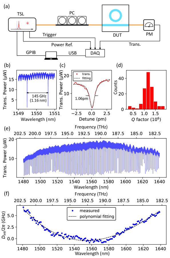
To study the device performance and phase matching condition, we first measure the device transmission using the setup shown in Fig. 2(a). A tunable semiconductor laser (TSL, santec TSL-710) is used to sweep the wavelength from 1480 nm to 1640 nm. After aligning the input mode to launch only the fundamental TE mode using a fiber polarization controller (PC), the device is coupled with two lensed fibers, whose typical facet-to-facet loss is around dB in our experiments and placed over a thermoelectric cooler (TEC) to improve the thermal stability. The transmitted power from the device is then collected by a power meter (PM, Newport, 2936-C) and finally acquired by a data acquisition module as well as the laser sweeping trigger signal and power reference.
The transmission of this device near 1550 nm is shown in Fig. 2(e). A magnified view of the device transmission near 1550 nm is plotted in Fig. 2(b). The observed FSR is around 145 GHz near 1550 nm. The transmission spectrum of a single resonant dip is shown in Fig. 2(c). The dashed line is a Lorentzian fitting of the resonant dip, indicating a 1.06 pm width and a Q-factor of . The Q-factors of all the resonant dips within the wavelength range between 1480 nm and 1640 nm are counted and presented in Fig. 2(d). The maximum quality factor is and the mean quality factor is .
3.2 Dispersion analysis
Next, we analyzed the device dispersion of the ring resonator. Following the integrated dispersion approach[32], we evaluated the second-order mode dispersion of the silicon nitride ring cavity.
After the cavity resonant frequencies are extracted from the device transmission, a Taylor series can be used to expand the resonant frequencies with respect to the relative mode index , where corresponds to the pump mode during the SFWM.
| (1) |
where is the integrated dispersion and is the FSR of the angular frequency. As shown in Fig. 2(f), a polynomial fitting of the integrated dispersion of resonant frequency gives MHz and kHz, showing that the frequency mismatch between tens of modes is less than the width of the cavity resonant mode (132 MHz).
4 Broadband photon pair generation
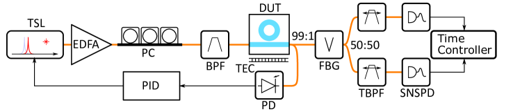
Finally, mode-resolvable photon pair generation is demonstrated using the setup shown in Fig. 3. To increase the pump power in the ring cavity, an erbium doped fiber amplifier (EDFA, Alnair Labs, HPA-200C) is employed as well as the TSL. The input polarization is aligned using a polarization controller. A bandpass filter is used to reject the sideband noise of the EDFA. The pump wavelength is set to 1550.63 nm to match the cavity resonant mode. The power measured before the device coupling is 24.5 mW. Considering the thermal instability during the pump wavelength location, a simple feedback loop is added in the scheme. At the device output port, a 99:1 beam splitter is connected for fine control of the pump wavelength to maintain resonance alignment. 1% of the device output is detected with a photodiode to monitor the ratio of the transmitted power to the input power, which is around dB during our experiments. The other 99% of the output power is filtered to reject the pump light with a fiber Bragg grating (FBG, OE Land) and then split into signal and idler channels using another 50:50 beam splitter. Tunable bandpass filters (TBPFs, WL Photonics) pass the needed signal and idler modes, with a band window of 0.12 nm, much narrower than the device mode spacing. Both channels are filtered to identify the signal or idler modes, and are finally detected with superconducting nanowire single photon detectors (SNSPDs, SCONTEL). Finally, a time-to-digital converter (ID Quantique, id900) records all the signal and idler counting events to allow evaluation of the photon pair generation rate for specific mode pairs. In order to confirm the frequency correlation for large bandwidth, we realized a stable measurement system where the wavelength of the narrow-band CW pump laser was actively controlled by proportional-integral-differential (PID) controller with monitoring the output pump laser power from the device.
To evaluate the photon pair generation rate, the losses of both the signal and idler channels are measured. The transmission of the lensed-fiber coupling is dB per facet. The measured total transmission of FBG, TBPF and beamsplitter is about dB. In the SNSPD, the detection efficiencies are 50%. Hence, the total detection efficiencies are dB for both signal and idler photons in our experiments.
5 Results and discussion
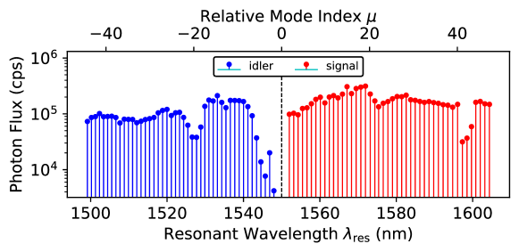
Fig. 4 shows the photon flux at cavity resonant modes, with red and blue corresponding to the signal and idler modes respectively. Here, mode 0 is set as the pump frequency. The photon flux of the th to st modes is significantly affected by the FBG used to stop the pump light. The mean photon flux for all the modes is up to cps.
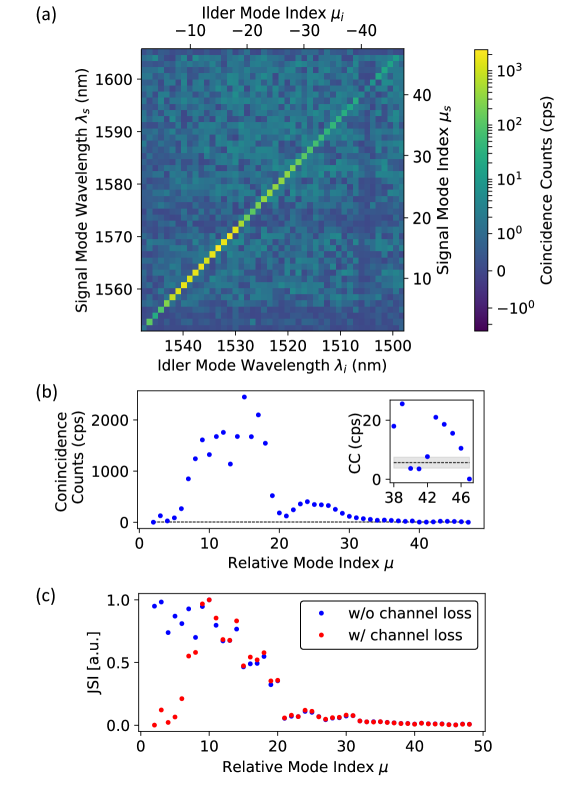
Next, the joint spectral intensity (JSI) of generated photon pairs is evaluated by coincidence counting (CC) with a time window of 1 ns and an accumulation time of 10 s for each mode-by-mode photon count. As shown in Fig. 5(a), for the ranges from mode 1499.09 nm () to 1548.32 nm () in the idler band, and from 1552.95 nm () to 1605.79 nm () in the signal band, the JSI map covers all the mode pairs. To reduce the effect of accidental counting events during the measurement, the accidental coincidence count (ACC), defined as , is subtracted from the result. The mean ACC for all the modes is 10.5 cps, and the coincidence to accidental ratios are of diagonal terms from 2th mode to 45th mode are larger than 1. Along the diagonal direction, the maximal CC is cps and decreases significantly as the relative mode index increases. This can be explained in terms of the dispersion of the device. As illustrated in Fig. 5(b), the highest value of the off-diagonal terms, i.e. non-phase matched modes, is 5.611.85 cps. This is higher than the counts for the 2nd, 40th, 41st and 47th mode pairs. Therefore, we conclude that 37 continuous mode pairs and a total of 42 mode pairs are generated in our experiment, which corresponds to a bandwidth of 51.25 nm in the signal band. Note that the full bandwidth of the photon-pairs from the th mode to 46th mode is 105.25 nm.
To clarify how the dispersion dominates the broadband SFWM process, we calculate the JSI of photons in the nonlinear cavity. Based on the resonant mode lineshape function and phase mismatch, the probability of two-photon state generation can be written as [25]
| (2) |
where is a constant of the cavity mode, including the detection channel loss coefficient; is the pump light lineshape function; is the frequency deviation from pump wavelength; is the cavity transmission given by a Lorentzian function:
| (3) |
where is the full width at half maximum (FWHM); and
| (4) |
is the mismatch due to the frequency mismatch and power-dependent self-phase modulation during four wave mixing phase, where is the mode integrated dispersion, is the cavity round-trip time, is the Kerr nonlinear coefficient and is the intracavity power of the pump light.
Thus, the diagonal terms in the JSI map can be evaluated numerically by substituting the retrieved cavity resonant frequencies and linewidths into Eq. 1. The result is presented in Fig. 5(c) and compared with the experimental CC result in Fig. 5(b). It can be seen that the numerical analysis agrees well with the experimental result of CC and thus validates the phase matching theory of SFWM. As shown in Fig. 5 (b) and 5 (c), the CCs around the 20th mode are significantly low. This can be explained by the term in Eq. (2), which relates the resonant frequencies and energy conservation of SFWM. The frequency mismatch between pump photons () and signal photon and idler photons () increases around the 20th mode.
6 Conclusion
In conclusion, we realized broadband frequency-correlated photon generation using a silicon nitride ring cavity. From the experimentally obtained JSI, we confirmed that the generated photon pairs are correlated in 37 continuous frequency mode pairs and a total of 42 mode pairs, which corresponds to a bandwidth of 51.25 nm in the signal band. Note that the full bandwidth of the photon-pairs from the th mode to 46th mode is 105.25 nm. The cavity is characterized for studying the phase matching condition. We then demonstrated broadband photon pair generation using 24.5 mW pump power. With these obtained data, we have successfully reconstructed the intensities of the diagonal part of JSI using the estimated dispersion without any fitting parameters. We anticipate that the on-chip scale nonlinear ring cavity will boost the development of scalable frequency-entangled photon sources and enable future frequency-encoded quantum technology.
Funding
JST-CREST (JPMJCR1674); MEXT Q-LEAP (JPMXS0118067634); JSPS-KAKENHI (26220712); Grant-in-Aid for JSPS Research Fellow (19J20968); MEXT WISE Program; Research Program for Next Generation Young Scientists of “Five-star Alliance" in “NJRC mater. & Dev.”.
Acknowledgments
We wish to acknowledge the helpful comments provided by Bo Cao, Takayuki Kiyohara and Xiaoyang Cheng.
Disclosures
The authors declare no conflicts of interest.
References
- [1] C. Weedbrook, S. Pirandola, R. García-Patrón, N. J. Cerf, T. C. Ralph, J. H. Shapiro, and S. Lloyd, “Gaussian quantum information,” \JournalTitleReviews of Modern Physics 84, 621–669 (2012).
- [2] V. Scarani, H. Bechmann-Pasquinucci, N. J. Cerf, M. Dušek, N. Lütkenhaus, and M. Peev, “The security of practical quantum key distribution,” \JournalTitleReviews of Modern Physics 81, 1301–1350 (2009).
- [3] V. Giovannetti, S. Lloyd, and L. Maccone, “Advances in quantum metrology,” \JournalTitleNature Photonics 5, 222–229 (2011).
- [4] C. L. Degen, F. Reinhard, and P. Cappellaro, “Quantum sensing,” \JournalTitleReviews of Modern Physics 89, 1–39 (2017).
- [5] P. Kok, W. J. Munro, K. Nemoto, T. C. Ralph, J. P. Dowling, and G. J. Milburn, “Linear optical quantum computing with photonic qubits,” \JournalTitleReviews of Modern Physics 79, 135–174 (2007).
- [6] T. Ono, R. Okamoto, M. Tanida, H. F. Hofmann, and S. Takeuchi, “Implementation of a quantum controlled-SWAP gate with photonic circuits,” \JournalTitleScientific Reports 7, 1–9 (2017).
- [7] R. Okamoto, J. L. O’Brien, H. F. Hofmann, and S. Takeuchi, “Realization of a knill-laflamme-milburn controlled-NOT photonic quantum circuit combining effective optical nonlinearities,” \JournalTitleProceedings of the National Academy of Sciences of the United States of America 108, 10067–10071 (2011).
- [8] S. Takeuchi, “Recent progress in single-photon and entangled-photon generation and applications,” \JournalTitleJapanese Journal of Applied Physics 53, 030101 (2014).
- [9] T. Kiyohara, R. Okamoto, and S. Takeuchi, “Unified integration scheme using an N × N active switch for efficient generation of a multi-photon parallel state,” \JournalTitleOptics Express 28, 17490 (2020).
- [10] T. Nagata, R. Okamoto, J. L. O’Brien, K. Sasaki, and S. Takeuchi, “Beating the standard quantum limit with four-entangled photons,” \JournalTitleScience 316, 726–729 (2007).
- [11] R. Okamoto, H. F. Hofmann, T. Nagata, J. L. O’Brien, K. Sasaki, and S. Takeuchi, “Beating the standard quantum limit: Phase super-sensitivity of N-photon interferometers,” \JournalTitleNew Journal of Physics 10, 073033 (2008).
- [12] M. Kues, C. Reimer, P. Roztocki, L. R. Cortés, S. Sciara, B. Wetzel, Y. Zhang, A. Cino, S. T. Chu, B. E. Little, D. J. Moss, L. Caspani, J. Azaña, and R. Morandotti, “On-chip generation of high-dimensional entangled quantum states and their coherent control,” \JournalTitleNature 546, 622–626 (2017).
- [13] C. Reimer, M. Kues, S. Sciara, P. Roztocki, M. Islam, L. Romero, C. Cortés, Y. Zhang, B. Fischer, S. S. S. Loranger, R. Kashyap, A. Cino, S. T. Chu, B. E. Little, D. J. Moss, L. Caspani, W. J. Munro, J. Joséazaña, R. Morandotti, L. Romero Cortés, Y. Zhang, B. Fischer, S. S. S. Loranger, R. Kashyap, A. Cino, S. T. Chu, B. E. Little, D. J. Moss, L. Caspani, W. J. Munro, J. Azaña, M. Kues, and R. Morandotti, “High-dimensional one-way quantum processing implemented on d-level cluster states,” \JournalTitleNature Physics 15, 148–153 (2019).
- [14] A. F. Abouraddy, M. B. Nasr, B. E. Saleh, A. V. Sergienko, and M. C. Teich, “Quantum-optical coherence tomography with dispersion cancellation,” \JournalTitlePhysical Review A - Atomic, Molecular, and Optical Physics 65, 6 (2002).
- [15] M. Okano, H. H. Lim, R. Okamoto, N. Nishizawa, S. Kurimura, and S. Takeuchi, “0.54 um Resolution Two-Photon Interference With Dispersion Cancellation for Quantum Optical Coherence Tomography,” \JournalTitleScientific Reports 5, 1–8 (2015).
- [16] S. Wengerowsky, S. K. Joshi, F. Steinlechner, H. Hübel, and R. Ursin, “An entanglement-based wavelength-multiplexed quantum communication network,” \JournalTitleNature 564, 225–228 (2018).
- [17] B. Dayan, A. Pe’er, A. A. Friesem, and Y. Silberberg, “Two photon absorption and coherent control with broadband down-converted light,” \JournalTitlePhysical Review Letters 93, 023005 (2004).
- [18] S. Sensarn, G. Y. Yin, and S. E. Harris, “Generation and compression of chirped Biphotons,” \JournalTitlePhysical Review Letters 104, 1–4 (2010).
- [19] A. Tanaka, M. Fujiwara, K. I. Yoshino, S. Takahashi, Y. Nambu, A. Tomita, S. Miki, T. Yamashita, Z. Wang, M. Sasaki, and A. Tajima, “High-speed quantum key distribution system for 1-mbps real-time key generation,” \JournalTitleIEEE Journal of Quantum Electronics 48, 542–550 (2012).
- [20] L. Razzari, D. Duchesne, M. Ferrera, R. Morandotti, S. Chu, B. E. Little, and D. J. Moss, “CMOS-compatible integrated optical hyper-parametric oscillator,” \JournalTitleNature Photonics 4, 41–45 (2010).
- [21] C. Reimer, L. Caspani, M. Clerici, M. Ferrera, M. Kues, M. Peccianti, A. Pasquazi, L. Razzari, B. E. Little, S. T. Chu, D. J. Moss, and R. Morandotti, “Integrated frequency comb source of heralded single photons,” \JournalTitleOptics Express 22, 6535 (2014).
- [22] C. Reimer, M. Kues, P. Roztocki, B. Wetzel, F. Grazioso, B. E. Little, S. T. Chu, T. Johnston, Y. Bromberg, L. Caspani, D. J. Moss, and R. Morandotti, “Generation of multiphoton entangled quantum states by means of integrated frequency combs,” \JournalTitleScience 351, 1176–1180 (2016).
- [23] P. Roztocki, M. Kues, C. Reimer, B. Wetzel, S. Sciara, Y. Zhang, A. Cino, B. E. Little, S. T. Chu, D. J. Moss, and R. Morandotti, “Practical system for the generation of pulsed quantum frequency combs,” \JournalTitleOptics Express 25, 18940 (2017).
- [24] K. Sugiura, R. Okamoto, L. Zhang, L. Kang, J. Chen, P. Wu, S. T. Chu, B. E. Little, and S. Takeuchi, “An on-chip photon-pair source with negligible two-photon absorption,” \JournalTitleApplied Physics Express 12, 022006 (2019).
- [25] K. Sugiura, Z. Yin, R. Okamoto, L. Zhang, L. Kang, J. Chen, P. Wu, S. T. Chu, B. E. Little, and S. Takeuchi, “Broadband generation of photon-pairs from a CMOS compatible device,” \JournalTitleApplied Physics Letters 116, 224001 (2020).
- [26] D. J. Moss, R. Morandotti, A. L. Gaeta, and M. Lipson, “New CMOS-compatible platforms based on silicon nitride and Hydex for nonlinear optics,” \JournalTitleNature Photonics 7, 597–607 (2013).
- [27] P. Imany, J. A. Jaramillo-Villegas, O. D. Odele, K. Han, D. E. Leaird, J. M. Lukens, P. Lougovski, M. Qi, and A. M. Weiner, “50-GHz-spaced comb of high-dimensional frequency-bin entangled photons from an on-chip silicon nitride microresonator,” \JournalTitleOptics Express 26, 1825 (2018).
- [28] J. Chen, Z. H. Levine, J. Fan, and A. L. Migdall, “Frequency-bin entangled comb of photon pairs from a Silicon-on-Insulator micro-resonator,” \JournalTitleOptics Express 19, 1470 (2011).
- [29] X. Cheng, J. Hong, A. M. Spring, and S. Yokoyama, “Fabrication of a high-Q factor ring resonator using LSCVD deposited Si_3N_4 film,” \JournalTitleOptical Materials Express 7, 2182 (2017).
- [30] M. H. Pfeiffer, J. Liu, M. Geiselmann, and T. J. Kippenberg, “Coupling Ideality of Integrated Planar High- Q Microresonators,” \JournalTitlePhysical Review Applied 7, 024026 (2017).
- [31] M. H. P. Pfeiffer, C. Herkommer, J. Liu, T. Morais, M. Zervas, M. Geiselmann, and T. J. Kippenberg, “Photonic damascene process for low-loss, high-confinement silicon nitride waveguides,” \JournalTitleIEEE Journal of Selected Topics in Quantum Electronics 24, 1–11 (2018).
- [32] V. Brasch, M. Geiselmann, T. Herr, G. Lihachev, M. H. Pfeiffer, M. L. Gorodetsky, and T. J. Kippenberg, “Photonic chip-based optical frequency comb using soliton Cherenkov radiation,” \JournalTitleScience 351, 357–360 (2016).