Distortion modes in halide perovskites: to twist or to stretch, a matter of tolerance and lone pairs
Abstract
Using first-principles calculations, we show that CsBX3 halides with B=Sn or Pb undergo octahedral rotation distortions, while for B=Ge and Si, they undergo a ferro-electric rhombohedral distortion accompanied by a rhombohedral stretching of the lattice. We show that these are mutually exclusive at their equilibrium volume although different distortions may occur as function of lattice expansion. The choice between the two distortion modes is in part governed by the Goldschmidt tolerance factor. However, another factor explaining the difference between Sn and Pb compared with Ge and Si is the stronger lone-pair character of Ge and Si when forced to be divalent as is the case in these structures. The lone-pair chemistry is related to the off-centering. While the Si-based compounds have not yet been synthesized, the Ge compounds have been established experimentally. As a final test of the importance of the tolerance factor we consider RbGeX3, which has smaller tolerance factor than the corresponding CsGeX3 because Rb is smaller than Cs. We find that it can lower its energy by both rotations or rhombohedral off-centering distortions but the latter lower the energy slightly more efficiently.
I Introduction
The cubic perovskite structure is well known from the oxide perovksites to exhibit various possible phase transitions. These fall in two main categories: ferro-electric distortions, in which the atom in ABX3 is displaced within its surrounding octahedron, and antiferro-electric distortions, in which the octahedra rotate, possibly about multiple axes. Depending on the type of displacement, for example along a cubic axis such as [001], or along two cubic axis or a [110] direction, or three cubic axes, corresponding to the [111] axis, the resulting symmetry becomes tetragonal, orthorhombic or rhombohedral. Likewise for the rotation type instabilities, rotation about one cubic axis leads to a tetragonal structure, about two orthogonal axes leads to an orthorhombic phase.
The halide perovskites with B=Pb, Sn, Ge have recently garnered a lot of attention, mostly driven by the hybrid organic/inorganic halides’ demonstrated potential for solar cell applications.Kojima et al. (2009); Lee et al. (2012); Ball et al. (2013); Eperon et al. (2014); Liu et al. (2013); Burschka et al. (2013); Kim et al. (2014); Park (2015) In particular methyl ammonium lead iodide (CH3NH3PbI3 or (MA)PbI3 or MAPI) and closely related materials have reached larger than 20 % efficiencies in solar cells in a record development time frame. The interplay between the dipole character and the orientation of the organic component and the inorganic framework leads to interesting effects on the above mentioned phase transitions.Quarti et al. (2014); Li and Rinke (2016) However, similar phase transitions also occur in the purely inorganic CsBX3 family. While these distortions, which are related to soft-phonon mode instabilities,Huang and Lambrecht (2014) lead to minor changes in the band structure, related to bond angle distortions, other phases are known in the halides, which are far more disruptive of the band structure. These latter phases include edge-sharing octahedra and exhibit band structures with much wider band gaps than their perovskite counterparts.Huang and Lambrecht (2013) As an example, the structural phases in CsSnI3 were studied in detail by In Chung et al. Chung et al. (2012). They fall generally in a set of three “black phases”, cubic, tetragonal and orthorhombic, which correspond to rotated octahedral structures, and another orthorhombic “yellow phase”, which has 1D chains of edge-sharing octahedra forming Sn2I structural motifs. It is notable that the transitions from cubic to tetragonal to orthorhombic perovksite each time increase the density and the yellow phase has an even higher density. The orthorhombic -phase is stable with respect to soft-phonons, but has been calculated to have an energy either lowerHuang and Lambrecht (2016) than or very closeda Silva et al. (2015) to that of the yellow phase.
Because the driving force for these transitions appears to be the increasing density, the occurrence of the edge-sharing octahedral structures, which appears to be detrimental for many of the sought applications, may perhaps be already inferred from the behavior of the material under octahedral rotations, which in turn is related to the relative sizes of the ions. For example, for the CsGeX3 compounds, the sequence of tetragonal, orthorhombic octahedral rotations is not observed and, to the best of our knowledges, no edge-sharing octahedral phase is known to occur, although a different, monoclinic phase occurs for the Cl members of the family. Instead of octahedral rotation phases, a ferro-electric rhombohedral distortion is found to occur in these materials, consisting of the displacement of the Ge along the body diagonal of the cubic unit cell, accompanied by a rhombohedral stretch of the unit cell.
In this paper we examine the behavior of a family of halide perovskites computationally under both octahedral rotation and rhombohedral ferro-electric distortions. Hence the phrase in the title: “to rotate or to stretch”. We find that the Sn and Pb members of the family of cubic perovskites are unstable toward rotation of the octahedra but stable with respect to ferro-electric distortions. In contrast, the Ge and Si based compounds show the opposite behavior: they are unstable towards ferro-electric distortion but are stable with respect to rotations. Furthermore we relate this distinct behavior to the Goldschmidt tolerance factor,Goldschmidt (1926) which provides a convenient way to summarize the relative ionic sizes. Notably, we include here the Si based halide perovskites, which have, as far as we known, not yet been synthesized.
The remainder of the paper is organized as follows. The details of our computational approach are given in Sec. II. The relationships between the different crystal structures and distortions to be studied are given in Sec. III. The results Sec. IV is divided in several subsections. First, we give a qualitative discussion in Sec. IV.1 establishing the different behavior of Sn and Pb vs. Si and Ge. Next, we consider full relaxations of the rotationally distorted structures of Sn and Pb based compounds in Sec. IV.2, then the full relaxations of the rhomobohedral structures of the Ge and Si based compounds in Sec. IV.3. In Sec. IV.4 we study the competion between both types of distortion as function of lattice expansion for the Sn and Pb based systems. Finally in Sec. IV.5 we consider the RbGeX3 compounds and end with a summary of the results in Sec.V.
II Computational Methods
The calculations are performed within density functional theory in the local density (LDA) and/or generalized gradient (GGA) approximations. Specifially, we use the Perdew-Burke-Ernzerhof (PBE) form of GGA.Perdew et al. (1996) The full-potential linearized muffin-tin orbital (FP-LMTO) band-structure method is utilized.Methfessel et al. (2000); Kotani and van Schilfgaarde (2010) Within this method, the basis set consists of Bloch sums of atom centered spherical waves as envelope functions, described by smoothed Hankel functions,Bott et al. (1998) which are then augmented with solutions of the radial Schrödinger equation inside muffin-tin spheres and their energy derivatives. For the present calculations, a large basis set of with two sets of Hankel function decay constants and smoothing radii is used. Inside the sphere, augmentation is done to an angular momentum cut-off of . The Cs states are treated as valence electrons. Likewise for Rb, the semicore are treated as local orbitals. The Brillouin zone integrations are done with a -centered mesh.
The LDA turns out to significantly underestimate the lattice constants in these materials, much more than the GGA overestimates them. Although our initial study of the rotation or distortion patterns used the experimental lattice constants of the cubic phase, our final full relaxation are done within GGA-PBE.
III Crystal structures
We start from the cubic perovskite structure. In this structure, with a simple cubic Bravais lattice, for the composition ABX3, the atom occurs in the center of the cubic unit cell and is octahedrally surrounded by atoms on the face centers. The atoms occupy the corners of the cubic cell. The stability is governed among other by the Goldschmidt tolerance factor, , where , , are the ionic radii. Hence for the ionic spheres are touching and hence Goldschmidt’s original idea was that should not deviate too far from for the perovskite structure to be stable. When , the ion is somewhat too small for the interstitial space between the octahedra. This is what leads to the rotations, which tighten the space for the ion. In contrast, when , the octahedral space is too large for the ion, which might then be expected to shift in its surroundings to make stronger bonds with a subset of the 6 neighbors. On the other hand, it is not so clear a-priori whether this is related to the tolerance factor or to the lone-pair character of the B-cation.
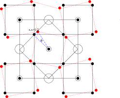
In terms of octahedral rotations, we consider both the in-phase and out-of-phase rotations about a single cubic axis. These both lead to a tetragonal structure, the first one having the space group No. 127, or , the second one space group No. 140 , or . They correspond to the Glazer tilt systemsGlazer (1972); Woodward (1997) and respectively. Although other Glazer tilt systems are possible and in fact occur in the Sn-halide perovskites,Huang and Lambrecht (2014) (a rotation about a second axis (Glazer leads to the orthorhombic or -phase), we here are primarily concerned with the instability either with respect to rotation of octahedra or ferro-electric distortions and thus consider the tetrahedral rotation as the trigger toward rotation behavior. So, we do not consider other tilt systems. In the tetragonal structure, the Wyckoff positions for the B-atoms is 2a, for the A-atom is 2c, for the X atoms, 2b and 4h. The parameter of the 4h positions is related to the rotation angle of the octahedron by as can be seen in Fig. 1. In fact, the blue rectangular triangle marked by one corner at position has sides and in units of the lattice constant and hence their ratio gives .
As far as the ferro-electric distortions, we only consider the rhombohedral structure corresponding to a displacement of the central ion along the [111] direction. In the prototypical ferro-electric oxide BaTiO3 this phase occurs at the lowest temperatures, with an orthorhombic and tetragonal phase occuring at higher temperatures and eventually a cubic phase. Cooling from high temperature, the displacement thus acquires successively more components along the cubic axes which deviate from the central position. While we presently do not exclude these other potential phases, our choice is guided by the CsGeX3 compounds, which have been found to exhibit this rhombohedral phase at low temperatures and a cubic phase at high temperatures but no other phases in between. The rhombohedral symmetry distortion of the ion is accompanied by a rhombohedral shear of the lattice vectors. Thus we will study the energy as function of displacement of the ion for varying rhombohedral strain.
| Ion | (Å) | |
|---|---|---|
| Cs | 1.88 | |
| Rb | 1.52 | |
| Si | 0.4 | |
| Ge | 0.53 | |
| Sn | 0.69 | |
| Pb | 0.775 | |
| Cl | 1.81 | |
| Br | 1.96 | |
| I | 2.2 | |
| Compound | rotations | |
| CsSiI3 | 1.10 | no |
| CsGeI3 | 1.057 | no |
| CsSnI3 | 0.998 | yes |
| CsPbI3 | 0.970 | yes |
| CsSiBr3 | 1.151 | no |
| CsGeBr3 | 1.090 | no |
| CsSnBr3 | 1.025 | yes |
| CsPbBr3 | 0.993 | yes |
| CsSiCl3 | 1.181 | no |
| CsGeCl3 | 1.115 | no |
| CsSnCl2 | 1.044 | yes |
| CsPbCl3 | 1.009 | yes |
| RbGeCl3 | 1.006 | yes |
| RbGeBr3 | 0.988 | yes |
| RbGeI3 | 0.964 | yes |
The occurrence of this distortion in Ge based halides but not in Sn or Pb based systems, which we will demonstrate later, is not only related to the Goldschmidt ratio of ionic sizes but is also related to the lone-pair character of the bonding. As one goes down the column of group-IV atoms, the valence states become increasingly deeper relative to the valence states. That is why carbon has and orbitals of similar extent and is extremely flexible in choosing different hybridization schemes: in graphite, in diamond and so on. Si and Ge clearly prefer hybridization and thus tend to be tetravalent, while Sn and Pb become increasingly divalent. Nonetheless, in the halide perovskite crystal structure, it is clear that even Ge behaves as a divalent ion. Whether Si can also be forced to be divalent in these compounds remains to be seen. However, the -electrons then behave as a stereochemically active lone-pair, which promotes off-centering of the Ge in its surrounding octahedron with an asymmetric bonding configuration in which the lone pair electrons are located opposite to the direction of the displacement of the ion.Walsh et al. (2011) The lone-pair related trends in the series Pb-Sn-Ge have been addressed by Waghmare et al. Waghmare et al. (2003) in the context of IV-VI compounds. We will show that even in the Sn-case this happens under lattice expansion, as was previously shown by Fabini et al. Fabini et al. (2016) According to the latest insights into lone-pair chemistry, the hybridization with the anion -orbitals play a crucial role in this. The important role of the Sn- halogen- hybridization on the band structure of CsSnX3 halides was already pointed out in our earlier work.Huang and Lambrecht (2013) We point out here that competition between rotation instabilities and lone-pair off-centering was previously studied in CsPbF3 by Smith et al. Smith et al. (2015) Lone pair physics related to Pb also occurs when Pb is the A-cation in oxide perovskites.Waghmare and Rabe (1997); Ghosez et al. (1999)
Finally, we should mention that the tolerance factor depends on the choice of ionic radii. Usually we use the ShannonShannon (1976) ionic radii for this purpose. However, these are themselves based on an analysis of bonding in different coordinations and for example do not give us any information on the behavior under hydrostatic pressure. One might conceivably think of the relative ion sizes to change with pressure or wish to include other aspects than pure ionic size to predict structural stability.Brehm et al. (2014); Travis et al. (2016) With these precautions, we used the Shannon ionic radii calculated tolerance factors as a guide to our study. They are summarized in Table 1. We note that our goal with the tolerance factor is not so much to predict structural maps in the sense of separating perovskite versus non-perovskite forming compounds but rather the type of structural distortion occurring within the perovskite. Also, because Shannon only provides ionic radii for Pb(II) in the divalent state, but not for Sn, Ge or Si, we used instead the tetravalent radii for octahedral environment. This may seem to contradict the fact that in these structures the B ion is supposed to be divalent. On the other hand, we should recognize that the bonding is partially covalent anyways. We find that within each group of a given anion, the tolerance factor decreases along the sequence Si-Ge-Sn-Pb. The dividing critical value between octahedral rotations being favored or not, depends actually on which anion (a similar point was also made by Travis et al. Travis et al. (2016)), but is close to 1 for all the Cs compounds. For the Cl compounds, it would be between 1.115 and 1.044. For Rb which has a smaller radius, the value 1.006 is thus definitely on the small side and hence predicts rotations to occur.
Our goal in this paper is to study the instability of the cubic structure to these two types of distortion as function of the atom and to correlate them with the tolerance factors in the above Table 1.
IV Results
IV.1 Qualitative discussion
First, we consider the CsSnI3 compound. In Fig. 2a we show its total energy as function of rotation angle of the octahedra. This calculation is done at the cubic experimental volume although we know that the observed -structure, corresponding to the space group has higher density. We consider both the in-phase and out-of-phase rotations. The figure shows that their energy is almost indistinguishable. More importantly, it shows clearly that the system prefers a rotation angle of about 6.9∘. Of course, the rotation can be either clockwise or counterclockwise. The energy barrier between the two is of the order of a few meV/formula unit. So, this agrees with the well-established fact that CsSnI3 undergoes octahedral rotations of this type although the equilibrium optimum angle appears to be somewhat underrestimated compared to the experimental angle which is 9∘, corresponding to the Wyckoff parameter . This is because in this initial calculation, we kept the cubic structure of the lattice and did not allow yet for a full relaxaton. Full relaxation results are given later in Table 2 and are discussed in subsection IV.2. The present result shows that the rotation instability is already present even at the volume of the cubic structure.
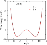
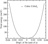
Next, we consider the behavior of CsSnI3 under the ferro-electric rhombohedral distortion. We do this at zero strain, so keeping the cubic lattice vectors. Clearly there is only one minimum at exactly the central position of the Sn in its octahedral cage. So, there is no evidence for a ferro-electric instability. Nonetheless, the curves are clearly not parabolic but show a rather flat energy minimum region for the position of the central atom.
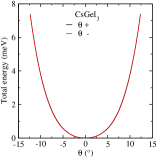
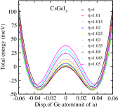
In contrast, if we consider CsGeI3, (Fig. 3a) for its rotational stability, we find no evidence at all of a rotational instability. The preferred angle is 0. This is true for both in-phase and out-of-phase rotations. On the other hand, in Fig.3b we see that now there is a clear instability against the ferro-electric displacement. Again, it is symmetric with respect to the central position. The displacement is given in units of the lattice constant of the cubic cell. The optimimum position lies between 0.52 and 0.54 or 0.46 and 0.48. In this case, we study the optimum position and the energy barrier as function of rhombohedral strain but initially keeping the volume fixed at that of the cubic structure. This is quantified by the parameter which gives the stretch along the [111] direction (when ) and is compensated by a compression in the orthogonal directions, which conserves the volume. Thus, we applied here a pure shear or traceless strain at fixed volume. We can see that the optimum position varies slightly with the strain. The lowest overall energy occurs for a strain of and . A full structural relaxation within the rhombohedral symmetry requires not only optimizing and but also the volume and the results of such a full relaxation are given in Table 3 in Sec. IV.3.
We thus see a mutually exclusive behavior of the two type of distortion modes. Either the material is unstable under rotations, or it is unstable under the ferro-electric distortion but not both. We found that these structural instabilities already occur at the cubic structure equilibrium volume but once the distortion takes place and full relaxation is allowed, a new equilibrium is found. We should remember though that the mutual exclusivity correspond to the experimental volume. This might change as function of pressure. For example, in SrTiO3, Zhong and VanderbiltZhong and Vanderbilt (1995) predict an interplay between the two types of distortions, leading eventually to a complex phase diagram as function of pressure and temperature. We will discuss the distortion behavior for CsSnI3 as function of lattice constant later.
Having established the basic two types of behavior, we now consider the variation with anion. In the CsSnBr3 and CsSnCl3 cases, we again find the structure to be stable against ferro-electric distortion, but unstable toward rotations. The energies as function of rotation angle are given in Suppelementary Material.sup For the CsGeBr3, CsGeCl3 cases, we find the structures to be stable under rotation as expected but we do find a ferro-electric distortion in both cases.sup Next we show that Pb behaves similar to Sn and Si behaves similar to Ge.sup For the Si case, where no experimental results are known, we initially used the LDA optimized lattice constants for the cubic CsSiX3 case but in the next section for our fully relaxed structures, we use GGA-PBE for improved accuracy.
IV.2 Full structural relaxation for Sn and Pb based rotations.
In this section we study the fully relaxed tetragonal structure corresponding to the
rotational distortions.
The optimum rotation angles are summarized in Table
2. Because we found LDA to underestimate the lattice constants more than GGA overstimates
them, we performed the full structural relaxations in GGA-PBE. In Table 2
we show both the results for the rotation angle when fixing the lattice constants to be “rotated cubic”
and fully relaxing the tetragonal structure, i.e. also relaxing . By “rotated cubic” we mean we consider a
superlattice in which the octahedrons can rotate as shown in Fig. 1
but keep the ratio exactly at a factor and keep the volume at the cubic volume. These results are also presented
in Fig. 4 to visualize the trends with halogen.
| Compound | CsSnI3 | CsSnBr3 | CsSnCl3 | |||
|---|---|---|---|---|---|---|
| Structure | ||||||
| (Å) | 8.935 | 8.800 | 8.372 | 8.282 | 8.033 | 7.942 |
| (Å) | 6.318 | 6.300 | 5.920 | 5.944 | 5.78 | 5.710 |
| (Å3) | 252.19 | 243.92 | 207.47 | 203.84 | 183.25 | 180.10 |
| (%) | -3.28 | -1.75 | -1.72 | |||
| (∘) | 6.93 | 10.1 | 3.61 | 8.85 | 2.49 | 8.32 |
| (meV) | 9.9 | 11.2 | 4.6 | 6.6 | 0.7 | 8.9 |
| Compound | CsPbI3 | CsPbBr3 | CsPbCl3 | |||
| Structure | ||||||
| (Å) | 9.065 | 8.610 | 8.514 | 8.367 | 8.160 | 8.034 |
| (Å) | 6.410 | 6.245 | 6.020 | 6.085 | 5.77 | 5.82 |
| (Å3) | 263.37 | 231.520 | 218.17 | 213.039 | 192.10 | 187.98 |
| (%) | -12.09 | -2.35 | -2.15 | |||
| (∘) | 10.75 | 12.36 | 9.13 | 12.36 | 8.58 | 11.77 |
| (meV) | 33 | 258 | 22 | 50 | 17 | 39 |
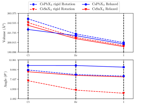
For CsSnI3, there are two sets of experimental results, by Yamada et al. Yamada et al. (1991) and by In Chung et al. Chung et al. (2012). Yamada et al. give Å, Å, Å3 for the -structure and Å, Å3 for the cubic structure, in other words, almost the same volume. In contrast, In Chun et al. Chung et al. (2012) give Å, Å, Å3 for the tetragonal and and Å, Å3 for the cubic structure. These results correspond to 500 and 380 K respectively and clearly show a smaller volume for the tetragonal structure. Our calculated results agrees qualitatively better with those of In Chun et al. Chung et al. (2012) in finding a volume reduction induced by the transition. Our GGA calculations overestimate the experimental volumes by about 5.6% and 3.6 % for the cubic and tetragonal structures compared to In Chung et al. Chung et al. (2012) We find systematically the same trend in volumes for the other compounds. We may note that the optimum rotation angle depends strongly on volume. It is typically larger in the relaxed tetragonal -structure than if we keep the volume fixed at the cubic volume. We may also note that it decreases with decreasing volume along the series CsSnI3, CsSnBr3, CsSnCl3 and similarly in the Pb based series. The rotation angles are larger in the Pb-based compounds than in the Sn-based compounds. This means the smaller the tolerance factor, the larger the rotation. Our optimum angle of octahedral rotation for CsSnI3 agrees well with the experimental value of 9.09∘.Yamada et al. (1991)
Finally we may note that for the larger cubic volumes, the rotation angle for the Sn-based compounds becomes rather small. Below, in Sec. IV.4, we show that under lattice constant expansion it actually goes to zero, and, at some critical volume, the ferro-electric distortion becomes preferable instead.
The energy barriers between the tetragonal energy minimum and the cubic unrotated structure are seen to be significantly larger for the Pb compounds than the Sn compounds and within each family decrease from I to Br to Cl, except for the fully relaxed CsSnBr3 and CsSnCl3.
IV.3 Full structural relaxation for Ge and Si based rhombohedral distortions.
| Compound | CsGeCl3 | CsGeBr3 | CsGeI3 |
|---|---|---|---|
| cubic GGA (Å3) | 155.72 | 177.50 | 216.00 |
| cubic Expt.(Å3) | 163.67 | 184.22 | 221.44 |
| rhombohedral (Å3) | 168.19 | 189.11 | 228.46 |
| rhombohedral (Å) GGA | 5.52 | 5.74 | 6.11 |
| rhombohedral (Å) Expt | 5.434 | 5.635 | 5.983 |
| 0.027 | 0.026 | 0.028 | |
| 0.015 | 0.011 | 0.008 | |
| 0.022 | 0.013 | 0.004 | |
| 1.014 | 1.023 | 1.024 | |
| GGA | 89.17 | 88.64 | 88.61 |
| Expt. | 89.72 | 88.74 | 88.61 |
| (meV) | 75 | 65 | 56 |
| (eV) GGA | 2.01 | 1.31 | 1.05 |
| Compound | CsSiCl3 | CsSiBr3 | CsSiI3 |
| cubic | 145.531 | 166.375 | 203.297 |
| rhombohedral (Å3) | 170.53 | 187.06 | 222.91 |
| rhombohedral (Å) | 5.54 | 5.71 | 6.06 |
| 0.038 | 0.029 | 0.052 | |
| 0.007 | 0.010 | 0.007 | |
| -0.057 | 0.033 | 0.018 | |
| 1.021 | 1.016 | 1.034 | |
| 88.79 | 89.05 | 88.00 | |
| (meV) | 357 | 235 | 142 |
| (eV) GGA | 2.02 | 1.31 | 0.605 |
In this section we further study the fully relaxed rhombohedrally distorted structures. In Table 3 we first give the optimum GGA volume of the cubic structure. It is compared with the experimental values at elevated temperature where that phase is stable, from Thiele et al. Thiele et al. (1987) at 170, 270 and 300 ∘C respectively for the Cl, Br, I cases. Clearly these values are larger than our GGA because of the lattice expansion at elevated temperature. Next, we applied a rhombohedral strain along the cubic structure, allowed the central Ge atom to go off-center by a displacement and allowed the volume to relax. The strain is applied along the [111] cubic direction while perpendicular to it, the distances are multiplied by , thus maintaining the volume. The strain tensor can be written to linear order
The cubic lattice vectors are thus distorted into vectors of with length which to first order in means they stay unchanged. The results for the Ge and Si based compounds are given in Table 3. We can see that for the Br and I cases, our relaxed lattice constant for the rhombohedral phase in GGA slightly overestimates the experimental value, even though the latter is measured at 20∘C while our calculated volume is in principle at 0 K. For the Cl case the calculated lattice constant is slightly underestimated.
The displacement from the 0.5 value is almost the same in all cases. The rhombohedral angle extracted from the shear using to linear order in strain agrees well with the experimental values. For the Si compounds, all values are obtained within GGA and no experimental values are available to compare with.
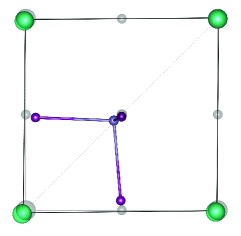
The full relaxation also requires the anions to move. For example the anion which in the cubic case is located at (0.5, 0, 0.5) moves to , in other words, it moves inward toward the displaced Ge as shown in Fig.7. The motion of the other anions is similarly determined by symmetry. The corresponding parameters are given in Table 3. Table 4 shows that the B-X bond lengths are shortened upon relaxation in spite of the overall volume being expanded in the rhombohedral distortion.
| Compound | cubic | relaxed | % change |
|---|---|---|---|
| CsGeCl3 | 2.69 | 2.49 | -7.88% |
| CsGeBr3 | 2.81 | 2.65 | -5.93% |
| CsGeI3 | 3 | 2.86 | -4.77% |
| CsSiCl3 | 2.63 | 2.31 | -13.91% |
| CsSiBr3 | 2.75 | 2.50 | -9.80% |
| CsSiI3 | 2.94 | 2.68 | -9.62% |
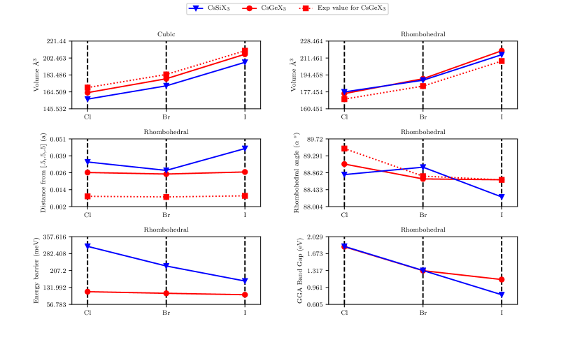
The energy differences between the cubic undistorted structure and the rhombohedral optimized structure each at their own equilibrium volume are also shown in Table 3. They indicate an increase from Cl to Br to I and much larger values for the Si then the Ge based compounds.
The band gaps, which must be underestimates because of the GGA, are also included in Table 3 and show the expected trend of decreasing from Cl to Br to I, in other words decreasing with decreasing ionicity. They are also smaller in the Si than the Ge compounds. The gaps in the approximation at the experimental rhombohedral structures for the CsGeX3 compounds were given in Ref. Huang and Lambrecht, 2016 and are 4.304, 2.654 and 1.619 eV for the Cl, Br and I cases respectively. For the Si- based compounds, they remain to be determined but assuming a similar gap correction, we can already see that both CsSiI3 and CsSiBr3 may have gaps suitable for photovoltaics. The trends of the data in Table 3 are visualized in Fig. 5.
Although the energy barriers increase from Cl to Br to I, they do not show a clear correlation with the transition temperatures, which are 277-283 ∘C, 238-242 ∘C, and 155 ∘C respectively for CsGeI3, CsGeBr3, CsGeCl3. The problem here is that our calculations consider a homogeneous transformaton, which is forced to be the same in each unit cell. In the actual phase transition, there is a competition between the interaction energies of atoms in neighboring cells and the double-well anharmonic potential well in each unit cell. The phase transition could be either displacive or order-disorder type.Dove (1997) In the former case, corresponding to a large interaction energy between neighboring cells, the positions of the atoms vibrate about an average near the barrier maximum (corresponding to the cubic structure) at high temperature and settle into one or the other minimum below the transition temperature. A nucleation process occurs where groups of neighboring atoms settle into one of the two local minima. In contrast in the order-disorder model, corresponding to a strong double well potential but weaker intercellular interactions, the atoms are always in one of the two minima but at high temperature, they are equally likely to be in the left or right well. From our present calculations, we do not have access to the inter-cell energies in such a model, and thus we cannot draw conclusions about the nature of the phase transition. Experimentally, it was established by Thiele et al. Thiele et al. (1987) that for CsGeBr3 and CsGeI3 the phase transition is first-order, while for the Cl-case it is second order. This would indicate a displacive transition for the latter case but an order-disorder type for the former.
IV.4 Rotation and rhombohedral distortion under volume expansion
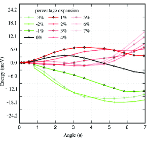
As we already mentioned, the tendency toward octahedral rotation in the Sn and Pb halides decreases, that is to say the rotation angle decreases, with increasing volume for a given material. We therefore further studied the behavior under lattice expansion and compression, which one might think of as occurring by thermal expansion and under high-pressure respectively. First, we show the energy curves for CsSnI3 as function of rotation angle for various lattice expansions in Fig. 7. Even without volume expansion, we see that the curves shows two local minima, one at zero angle and one at about 7∘. As we increase the volume, the local minimum corresponding to the finite rotation moves up in relative energy and eventually,beyond 3 % expansion of the lattice constants, it disappears, at which point the curve becomes very flat. Although they still show a very shallow finite angle minimum, we may essentially consider this as a sign that the rotation is no longer preferred. On the other hand, under compression, the local minimum appears to shift toward smaller angle and becomes deeper relative to the unrotated structure.
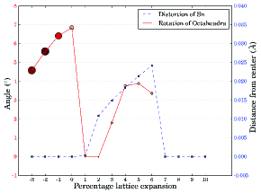
The optimum angle of rotation is shown as the red curve as function of lattice expansion in Fig. 8. The increasing values for lattice expansion actually correspond to a very low energy barrier, as is indicated by the small sign of the symbols marking each point and may to first approximation be ignored. Under compression, the rotation angle clearly is reduced and the barrier increases, meaning the energy of the rotated minimum becomes deeper.
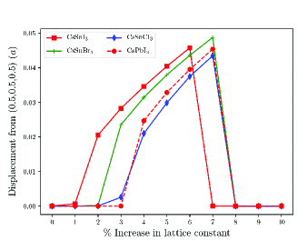
Next, we examine the possibility of off-centering of the Sn atom as function of lattice expansion. As we can see in Fig. 8 in the blue dashed curve, the off-centering displacement stays zero until 1 % expansion at which point it starts increasing linearly. Eventually it collapses again beyond 6 % expansion. Similar results are also obtained for the other halogens and for the Pb compounds as shown in Fig. 9. In summary, we find that beyond a given lattice expansion the CsSnX3 and CsPbX3 materials undergo a rhombohedral distortion with off-centering of the Sn (or Pb) rather than the octahedral rotation.
This type of behavior was reported earlier for CsSnBr3 by Fabini et al. Fabini et al. (2016) and related to the active lone-pair behavior of the electrons which was studied in detail. We thus see that there is indeed a competition between the two types of distortion behavior, rotation or rhombohedral off-centering. The lone pair character promotes the off-centering and is strongest for Ge and Si if the latter are required, as in this structure, to behave divalent but it also occurs in Sn and to a smaller degree in Pb. However, in Sn and Pb this mechanism of distortion is in competition with rotations, while in Ge and Si it is not. Finally, it should be pointed out that the off-centering in CsSnBr3 was experimentally observed by Fabini et al. Fabini et al. (2016) but occurs dynamically. It was observed only through analysis of the pair distribution functions. In other words, it does not occur coherently throughout the sample, which means that a rhombohedral crystallographic phase is not found for this compound. Instead it is hidden in the cubic phase but is apparent from the large atomic displacements which are coherent only on a local scale. This is an important difference from Ge where the rhombohedral phase is the actually observed equilibrium crystal structure.
IV.5 Rb instead of Cs
| Compound | RbGeCl3 | RbGeBr3 | RbGeI3 |
|---|---|---|---|
| Angle () | 4.71 | 6.93 | 10.21 |
| Energy barier (meV) | -70.0 | 13.5 | 36.4 |
In this section we consider the RbGeX3 compounds compared with the CsGeX3 compounds. From Table 1 we expect that because of the smaller size of the Rb ion, these compounds would be unstable toward octahedral rotation. The results for rotation in Table 5 show indeed that octahedral rotation lowers the energy for a finite rotation angle for I and Br but not for Cl. In the latter case, there is still a local minimum at a finite angle but its energy is actually higher than at the zero angle rotation. The energy lowering is comparable and even larger than for the corresponding CsSnX3 compounds and the angle of rotation is larger for I than for Br.
| Compound | RbGeCl3 | RbGeBr3 | RbGeI3 |
|---|---|---|---|
| Cubic (Å) GGA | 5.345 | 5.57 | 5.97 |
| Cubic (Å3) | 152.70 | 172.80 | 212.77 |
| Cubic bond length (Å) | 2.67 | 2.78 | 2.98 |
| Rhombohedral (Å3) | 5.44 | 5.65 | 5.99 |
| Rhombohedral (Å3) | 161.27 | 180.44 | 214.98 |
| Rhombohedral bond length (Å) | 2.31 | 2.46 | 2.69 |
| (%) | 5.31% | 4.23% | 1.02% |
| Change in bond length (%) | -13.37% | -11.55% | -9.84% |
| 0.035 | 0.038 | 0.036 | |
| 0.001 | 0.002 | 0.001 | |
| 0.011 | 0.025 | 0.014 | |
| 1.026 | 1.052 | 1.039 | |
| 88.47 | 87.00 | 87.71 | |
| (meV) GGA | 455.8 | 367.2 | 304.7 |
| Band Gap (eV) GGA | 1.72 | 1.05 | 0.43 |
On the other hand, from the previous sections, it is also clear that from the point of view of lone-pair physics, Ge is prone to off-centering. Therefore we also study the possibility of lowering the energy by the rhombohedral disotortion. The results are shown in Table 6. This shows that the off-centering and related rhombohedral distortion lowers the energy significantly more efficiently than the octahedral rotation. For RbGeCl3 the rotation actually does not lower the energy, while the distortion does. For RbGeBr3 and RbGeI3, the energy lowering by the off-centering is significatnly larger than by rotation of the octahedra. Thus comparing to the Cs case, this indicates that the off-centering of Ge is not so much determined by the tolerance factor but rather by the lone-pair physics. The relaxation parameters, barriers and energy gaps in GGA for these compounds are given in Table 6 in the same way as for the other compounds.
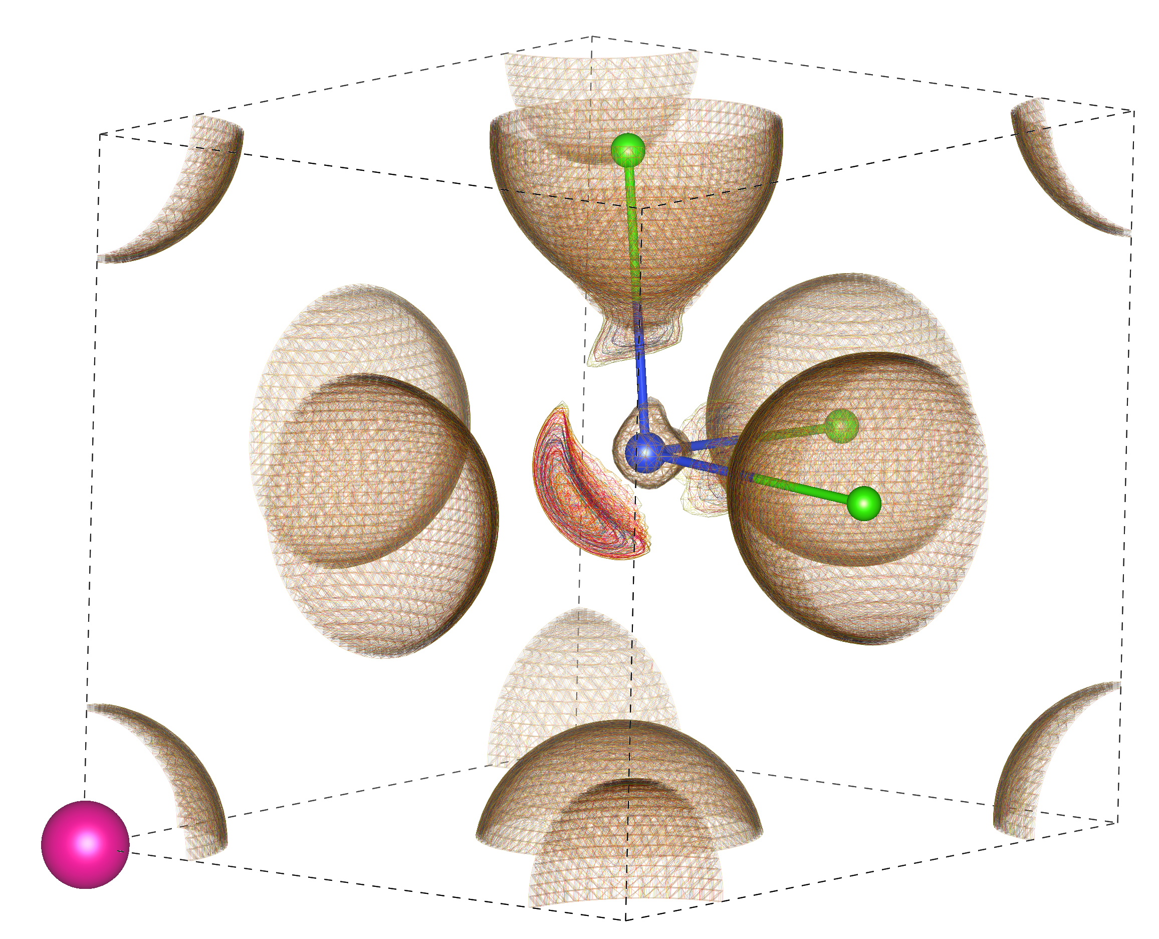
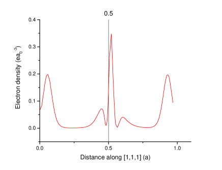
Finally, we illustrate the lone-pair character in this case by plotting the charge density for this in Figs. 10, 11. The firts one shows a 3D view of isosurfaces, the second one shows the valence charge density along the body diagonal.
V Conclusions
In this paper we have explored the stability of inorganic halide perovskites ABX3 with a halogen (Cl, Br, I), a large alkali ion(Cs or Rb) and B a group IV element, (Si, Ge, Sn, Pb), under two types of distortion: an antiferroelectric distortion corresponding to octahedral rotation and a ferro-electric off-centering of the central IV ion inside its halogen octahedron. At first, we find that there is a clear trend that the Pb and Sn cases prefer rotation while Ge and Si prefer ferro-electric distortion. We also find that the rotation, when fully optimizing the structures, is accompanied by a reduction of the volume. The off-centering is accompanied by rhombohedral distortion and volume increase. The tendency toward rotation is clearly related to the Goldschmidt tolerance factor. On the other hand, we find that upon volume expansion, the rotation angle decreases and beyond a certain expansion off-centering becomes favorable even for Sn and Pb based compounds. The origin of the off-centering is thus more related to the lone-pair physics. The Ge and Si based compounds, in which Ge and or Si are forced to behave as a divalent ion, strongly favor lone-pair induced off-centering or ferro-electric distortion. In the Rb case, both distortion modes tend to lower the energy (except for the Cl case) but the ferro-electric distortion nonetheless lowers the energy signiricantly more efficiently. Thus the lone-pair physics dominates the RbGeX3 based compounds rather than the tolerance factor related rotation. The two distortion mechanisms can thus be in competition with each other and the off-centering for the Si and Ge cases occurs even if the tolerance factor would allow for rotations as a mechanism to lower the energy.
Acknowledgements.
This work was supported by the U.S. Department of Energy (Basic Energy Sciences) DOE-BES under grant No. DE-SC0008933. The calculations made use of the High Performance Computing Resource in the Core Facility for Advanced Research Computing at Case Western Reserve University.References
- Kojima et al. (2009) A. Kojima, K. Teshima, Y. Shirai, and T. Miyasaka, Journal of the American Chemical Society 131, 6050 (2009), pMID: 19366264, http://dx.doi.org/10.1021/ja809598r .
- Lee et al. (2012) M. M. Lee, J. Teuscher, T. Miyasaka, T. N. Murakami, and H. J. Snaith, Science 338, 643 (2012).
- Ball et al. (2013) J. M. Ball, M. M. Lee, A. Hey, and H. J. Snaith, Energy Environ. Sci. 6, 1739 (2013).
- Eperon et al. (2014) G. E. Eperon, V. M. Burlakov, P. Docampo, A. Goriely, and H. J. Snaith, Advanced Functional Materials 24, 151 (2014).
- Liu et al. (2013) M. Liu, M. B. Johnston, and H. J. Snaith, Nature 501, 395 (2013).
- Burschka et al. (2013) J. Burschka, N. Pellet, S.-J. Moon, R. Humphry-Baker, P. Gao, M. K. Nazeeruddin, and M. Grätzel, Nature 499, 316 (2013).
- Kim et al. (2014) H.-S. Kim, S. H. Im, and N.-G. Park, The Journal of Physical Chemistry C 118, 5615 (2014).
- Park (2015) N.-G. Park, Materials Today 18, 65 (2015).
- Quarti et al. (2014) C. Quarti, E. Mosconi, and F. D. Angelis, Chem. Mater. 26, 6557 (2014).
- Li and Rinke (2016) J. Li and P. Rinke, Phys. Rev. B 94, 045201 (2016).
- Huang and Lambrecht (2014) L.-y. Huang and W. R. L. Lambrecht, Phys. Rev. B 90, 195201 (2014).
- Huang and Lambrecht (2013) L.-y. Huang and W. R. L. Lambrecht, Phys. Rev. B 88, 165203 (2013).
- Chung et al. (2012) I. Chung, J.-H. Song, J. Im, J. Androulakis, C. D. Malliakas, H. Li, A. J. Freeman, J. T. Kenney, and M. G. Kanatzidis, Journal of the American Chemical Society 134, 8579 (2012), http://pubs.acs.org/doi/pdf/10.1021/ja301539s .
- Huang and Lambrecht (2016) L.-y. Huang and W. R. L. Lambrecht, Phys. Rev. B 93, 195211 (2016).
- da Silva et al. (2015) E. L. da Silva, J. M. Skelton, S. C. Parker, and A. Walsh, Phys. Rev. B 91, 144107 (2015).
- Goldschmidt (1926) V. M. Goldschmidt, Naturwissenschaften 14, 477 (1926).
- Perdew et al. (1996) J. P. Perdew, K. Burke, and M. Ernzerhof, Phys. Rev. Lett. 77, 3865 (1996).
- Methfessel et al. (2000) M. Methfessel, M. van Schilfgaarde, and R. A. Casali, in Electronic Structure and Physical Properties of Solids. The Use of the LMTO Method, Lecture Notes in Physics, Vol. 535, edited by H. Dreyssé (Berlin Springer Verlag, 2000) p. 114.
- Kotani and van Schilfgaarde (2010) T. Kotani and M. van Schilfgaarde, Phys. Rev. B 81, 125117 (2010).
- Bott et al. (1998) E. Bott, M. Methfessel, W. Krabs, and P. C. Schmidt, Journal of Mathematical Physics 39, 3393 (1998), http://dx.doi.org/10.1063/1.532437 .
- Glazer (1972) A. M. Glazer, Acta Crystallographica Section B 28, 3384 (1972).
- Woodward (1997) P. M. Woodward, Acta Cryst. B53, 44 (1997).
- Walsh et al. (2011) A. Walsh, D. J. Payne, R. G. Egdell, and G. W. Watson, Chem. Soc. Rev. 40, 4455 (2011).
- Waghmare et al. (2003) U. V. Waghmare, N. A. Spaldin, H. C. Kandpal, and R. Seshadri, Phys. Rev. B 67, 125111 (2003).
- Fabini et al. (2016) D. H. Fabini, G. Laurita, J. S. Bechtel, C. C. Stoumpos, H. A. Evans, A. G. Kontos, Y. S. Raptis, P. Falaras, A. Van der Ven, M. G. Kanatzidis, and R. Seshadri, Journal of the American Chemical Society 138, 11820 (2016), pMID: 27583813, http://dx.doi.org/10.1021/jacs.6b06287 .
- Smith et al. (2015) E. H. Smith, N. A. Benedek, and C. J. Fennie, Inorganic Chemistry 54, 8536 (2015), pMID: 26295352, https://doi.org/10.1021/acs.inorgchem.5b01213 .
- Waghmare and Rabe (1997) U. V. Waghmare and K. M. Rabe, Phys. Rev. B 55, 6161 (1997).
- Ghosez et al. (1999) P. Ghosez, E. Cockayne, U. V. Waghmare, and K. M. Rabe, Phys. Rev. B 60, 836 (1999).
- Shannon (1976) R. D. Shannon, Acta Cryst. A 32, 751 (1976).
- Brehm et al. (2014) J. A. Brehm, J. W. Bennett, M. R. Schoenberg, I. Grinberg, and A. M. Rappe, The Journal of Chemical Physics 140, 224703 (2014), http://dx.doi.org/10.1063/1.4879659 .
- Travis et al. (2016) W. Travis, E. N. K. Glover, H. Bronstein, D. O. Scanlon, and R. G. Palgrave, Chem. Sci. 7, 4548 (2016).
- Zhong and Vanderbilt (1995) W. Zhong and D. Vanderbilt, Phys. Rev. Lett. 74, 2587 (1995).
- (33) A more complete set of results as function of rotation and/or ferro-electric distortion is provided in the Supplementary Materials accompanying this paper.
- Yamada et al. (1991) K. Yamada, S. Funabiki, H. Horimoto, T. Matsui, T. Okuda, and S. Ichiba, Chemistry Letters 20, 801 (1991).
- Thiele et al. (1987) G. Thiele, H. W. Rotter, and K. D. Schmidt, Z. anorg. allg. Chem. 545, 148 (1987).
- Dove (1997) M. T. Dove, American Mineralogist 82, 213 (1997).