Resonant spin amplification in Faraday geometry
Abstract
We demonstrate the realization of the resonant spin amplification (RSA) effect in Faraday geometry where a magnetic field is applied parallel to the optically induced spin polarization so that no RSA is expected. However, model considerations predict that it can be realized for a central spin interacting with a fluctuating spin environment. As a demonstrator, we choose an ensemble of singly-charged (In,Ga)As/GaAs quantum dots, where the resident electron spins interact with the surrounding nuclear spins. The observation of RSA in Faraday geometry requires intense pump pulses with a high repetition rate and can be enhanced by means of the spin-inertia effect. Potentially, it provides the most direct and reliable tool to measure the longitudinal factor of the charge carriers.
The possibility of using the spin degree of freedom for quantum information [1, 2] continues to drive research on semiconductor nanostructures [3, 4, 5, 6]. The main characteristic in this field is defined by the lifetime of the information or the spin coherence time. Complementarily, the development of spintronics [7] over two decades gave birth to a plethora of experimental tools for the investigation of the spin dynamics in semiconductor nanostructures. A major part of these methods is based on the interrelation between the spin of a charge carrier and the polarization of a photon emitted or absorbed by the semiconductor structure [8]. The most popular ones are the Hanle effect [9] and the time-resolved pump-probe technique, based on the pulsed-laser excitation [10, 11, 12], which can be extended to detect the spin dynamics on arbitrary long timescales with femtosecond resolution [13]. Other powerful tools are the spin-noise spectroscopy [14, 15] and the spin-inertia technique [16, 17, 18, 19].
One of the most basic parameters of the spin dynamics is the factor, which is often anisotropic in semiconductor nanostructures. Its transverse component can be measured very precisely when a magnetic field is applied in Voigt geometry by means of the resonant spin amplification (RSA) effect [20]. It is based on the pump-probe technique, where the spin polarization is measured at a fixed pump-probe delay as a function of a transverse magnetic field. Provided the spin relaxation time is longer than the laser repetition period, the spin polarization is amplified when the Larmor precession period is a multiple integer of the laser repetition period [10]. The RSA effect can also be used to evaluate the spin relaxation time, the spread of the transverse factor, and the strength of the hyperfine interaction [21]. The RSA method has been successfully applied to a variety of systems, ranging from bulk GaAs [20], III-V and II-VI quantum wells and epilayers [22, 23, 24], to quantum dots [25, 26].
In Faraday geometry where the magnetic field is parallel to the optical axis, there is no spin precession of the charge carriers on average such that it is difficult to determine their factor. Up to now, it must be measured indirectly: First, the transverse factor is determined in Voigt geometry, e.g., by standard RSA [20] or from time-resolved measurement of quantum beats [27, 28, 29]. Repeating the measurements in an oblique geometry (e.g., tilted by ) gives access to the longitudinal factor [27, 23]. In this Letter, we propose a RSA-based method to measure the longitudinal factor directly and with high accuracy. More precisely, we demonstrate that RSA can emerge in Faraday geometry for an ensemble of -doped (In,Ga)As/GaAs quantum dots (QDs). The effect is enabled by the hyperfine interaction between the resident electron spins and the fluctuating nuclear spin environment [19].
Experimental details –
The studied sample consists of 20 layers of (In,Ga)As QDs separated by -nm barriers of GaAs and grown by molecular beam epitaxy on a (100)-oriented GaAs substrate. A -doping layer of silicon nm above each QD layer provides a single electron per QD on average. Rapid thermal annealing at C for s homogenizes the QD size distribution and shifts the average emission energy to eV. The QD density per layer amounts to .
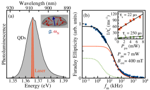
The sample is cooled to K in a Helium gas atmosphere inside a cryostat with a split-coil magnet. A superconducting solenoid pair creates an external magnetic field in the direction of light incidence, i.e., along the optical axis with an accuracy of 2 degree (Faraday geometry). The sample is illuminated by laser pulses with a central optical energy of eV and a full width at half maximum of meV. The pulses have a duration of ps and are emitted with a repetition frequency of GHz. They are split in pump and probe pulses, which are degenerate in photon energy and shifted by meV to the low-energy flank of the QD photoluminescence, see Fig. 1(a). The pump pulses are directed along a variable mechanical delay line. A double-modulation scheme reduces the noise arising from separate detection of the scattered pump and probe light. The helicity of the pump is modulated by an electro-optical modulator at a frequency between left- and right-handed circular polarization ranging from to kHz, preventing the build-up of significant dynamic nuclear polarization [30]. The linearly polarized probe beam is intensity modulated using a photoelastic modulator at a frequency of kHz in series with a Glan prism. For signal detection, the reference frequency of the lock-in amplifier is running at the difference frequency. The pump and the probe beams are focused on the same sample spot, with the pump focused to a spot diameter of m and the probe to a diameter of m. We measure the Faraday ellipticity amplitude of the probe pulses using an optical polarization bridge, which consists of a lambda-quarter plate, a Wollaston prism, and a balanced photodetector. The Faraday ellipticity is proportional to the electron spin polarization of the QDs along the optical axis [31].
Results –
Each circularly polarized pump pulse partially orients the spins of the resident electrons along the optical axis [32]. The spin polarization added by each pulse in this way depends on its effective pulse area [28], which is determined by the average pump beam power and scales like when the power is small [31]. If the added spin polarization exceeds the relaxed polarization along the optical axis until the next pulse, the spin polarization builds up. This is the case for a magnetic field of mT using a pump power of mW, and the origin for the spin polarization in Fig. 1(b) displayed by the Faraday ellipticity at ps time delay between pump and probe pulses studied as a function of the pump modulation frequency . The decay of the ellipticity upon increasing stems from the spin-inertia effect [16, 17, 18, 19]. It can be described by the dependence , where is the effective spin lifetime at the corresponding pump power. The extrapolation of to zero power allows for extracting the intrinsic spin relaxation of the electrons [16, 19]. The inset in Fig. 1(b) depicts the extracted times for two components present in the spin-inertia dependence shown as solid-red and dashed-green curves. We relate them to two effective subsets of electrons in the QD ensemble and focus on the regime kHz for which only the shorter living subensemble with s contributes significantly 111Probably, there is a continuous distribution of spin relaxation times due to the inhomogeneous character of the QD ensemble. However, this is difficult to describe by our model where only a single spin relaxation time enters for the ground state [34]. In any case, a single-component fit of the spin-inertia dependence is much worse than the two-component fit which captures all effects important for the following analysis..
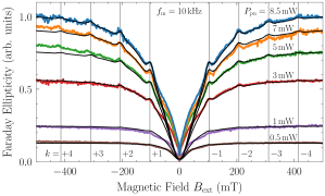
Without a magnetic field, the spin polarization of the electrons decays due to the hyperfine interaction with the nuclear spin fluctuations [35]. The application of a longitudinal magnetic field suppresses the nuclei-induced spin relaxation and in turn increases the spin polarization [36]. This effect is referred to as polarization recovery. For the -doped QD sample studied in this work, the polarization recovery curves (PRCs) have the typical -like shape (symmetric around zero field) [37, 17, 18, 19, 36]. Figure 2 shows the PRCs for a wide range of pump powers. For small powers, the electron spin polarization is minimal at mT and rises to a saturation level within mT. For zero field, the electron spin is only subject to the isotropic nuclear fluctuation field characterized by the frequency MHz 222The value MHz is estimated by fitting our model [34] to the measured PRCs. The width of the zero-field minimum does not only depend on but also on other parameters due to saturation effects [19]. Furthermore, there are also contributions from resident or photoexcited holes as we will discuss later. Hence, we mainly focused on fitting to the width of the later introduced RSA modes, which appears to be robust against variations of the other parameters. (equivalent to a field of mT), which is the characteristic frequency of the electronic Larmor precession in the nuclear fluctuation field (Overhauser field) leading to nuclei-induced spin relaxation; see the sketch in Fig. 1(a). Upon increase of the longitudinal magnetic field, the role of the Overhauser field is reduced due to the increase of the electronic Zeeman splitting. In a classical picture, the amplitude of the electron spin precession about the resulting effective magnetic field (superposition of Overhauser and external field; see the sketch in Fig. 3) is reduced the more the larger the external field. Hence, the lifetime of the spin polarization and therefore the polarization itself increases until saturation is reached [39].
For larger pump powers, the spin polarization increases and the qualitative dependence on the magnetic field is very similar. But strong pulses suppress the in-plane electron spin components, effectively accelerating the spin relaxation, which in turn leads to a broadening of the zero-field minimum in the PRC [19, 36]. Clearly, this is the case in Fig. 2: The larger the pump power, the larger the required magnetic field to reach saturation.
The appearance of a modulation in the Faraday ellipticity at certain values of the longitudinal magnetic field in the case of large pump powers is most striking. This is the result of RSA in Faraday geometry enabled by nuclear fluctuation fields [19]. As demonstrated in Fig. 2, the modulations appear at magnetic fields which fulfill the phase synchronization condition (PSC)
| (1) |
for the Larmor frequency ( is the Bohr magneton and the reduced Planck constant). These discrete resonance frequencies are given by multiples of the laser repetition frequency . We label them by the mode number . The longitudinal electronic factor determines the mode positions. While we cannot extract its sign from this effect, we know that it is negative for similar (In,Ga)As/GaAs QDs [29]. Taking all peak positions into account, we obtain . For comparison, the transverse factor of the electrons in this sample amounts to 333The transverse factor is determined from time-resolved measurements of the spin dynamics in a transverse magnetic field of T..
The theoretical model is presented in the Supplemental Material [34]. It almost perfectly describes the experiment as shown by the black lines in Fig. 2. Noteworthy, in contrast to Refs. [31, 18, 19], the model accounts for a lifetime of the photoexcited trion which is comparable to the pulse repetition period of ns. The main deviation between experiment and theory is found in the regime of very small magnetic fields. This deviation has a narrow -like shape, which is typical for -doped QD samples with a strong field dependent spin generation rate [17, 18]. Hence, we attribute the deviation to resident or photoexcited hole spins with weak hyperfine interaction.
In what follows, we describe how the nuclear fluctuation fields in QDs enable us to implement RSA in Faraday geometry. In a single QD, the localized electron spin precesses in an effective magnetic field being the sum of the external and the Overhauser field with frequency . The Larmor frequency points along the external magnetic field. But the Overhauser field , whose time evolution is much slower than the pulse repetition rate [35], has a random direction, which tilts the effective field from the axis due to its transverse components. As illustrated by the sketch in Fig. 3, this tilt leads to a precession motion, which becomes smaller in amplitude for a larger magnetic field. This is the reason why the higher RSA modes in Fig. 2 are less pronounced. Strong pulses result in a strong generation of spin polarization while also aligning the electron spin along the axis, leading to RSA whenever the PSC for a single QD is met. After averaging over the Overhauser field distribution described by Gaussian fluctuations with variance [35, 41], the PSC (1) follows in leading order for [19]. Corrections to the resonance frequency are . For , the modes appear shifted. We point out that this mechanism is expected to work also for single QDs because the statistical fluctuations of the Overhauser field in time can be described by the same distribution as for the ensemble [35, 41].
RSA in Faraday geometry should be detectable in a variety of semiconductor nanostructures. But the ensemble average smears out the RSA modes such that they cannot be observed unless certain conditions are met. The prerequisites are: (i) an efficient hyperfine coupling, (ii) strong pump pulses, and (iii) a laser repetition frequency which on the one hand allows for RSA modes that are separated enough not to overlap significantly, but on the other hand fall into magnetic field ranges where the spin polarization is not yet saturated [19]. The conditions (i) and (ii) are typically fulfilled for singly-charged -type (In,Ga)As/GaAs QDs [42]. For -type QDs with strongly anisotropic hyperfine interaction [43, 44], the effect is exptected to be much weaker [19]. The condition (iii) is not trivial and potentially leads to a new regime of the spin dynamics. An estimate for its realization is the condition known from standard RSA [26]. We implemented a laser source with repetition rate GHz to reach this regime.
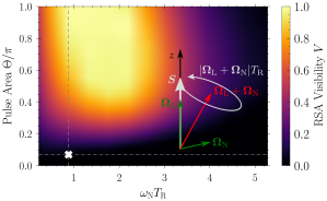
To provide a quantitative basis for the above, we study the RSA visibility defined as [36]
| (2) |
where is the Faraday ellipticity of the first maximum at the RSA mode and denotes the adjacent minimum for larger magnetic field . In order to average out statistical fluctuations in both model and experiment, we fit polynomials to the region around the mode to determine its visibility. A map of the RSA visibility in dependence of the pulse area (defined in the Supplemental Material [34]) and of the product ( is the pulse repetition period) is shown in Fig. 3. The visibility is enhanced by an increase of the pulse area corresponding to stronger pulses. For a too large or too small repetition period, the visibility decreases. Observing RSA in Faraday geometry is easiest in the intermediate regime . The white cross on the color map shows that the laser source used here is operating at a too small power with a resulting visibility of merely at a pump power of mW. Under optimal conditions, the visibility could reach unity. For the commonly used pulse repetition periods and ns ( and ), no RSA modes are discernible for our QD sample with MHz because they overlap.
The main obstacle for a larger visibility is the small pulse area of the applied GHz pulses because a too large pump power would heat the sample too much. Yet, we can study the power dependence of the experimentally seen and theoretically modeled visibility in the accessible range. Clearly, as demonstrated in Fig. 4(b) by experiment and theory, a reduction of the pump power results in the disappearance of the RSA modes displayed by a vanishing visibility.
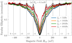
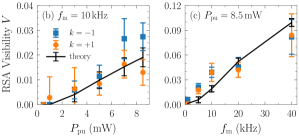
Remarkably, the RSA visibility can be enhanced by exploiting the spin-inertia effect. This is demonstrated in Fig. 4(a) where PRCs for various pump modulation frequencies are plotted using a pump power of mW. The PRCs are normalized with respect to the Faraday ellipticity at mT to highlight the enhanced visibility of the RSA modes upon increasing . The deviation between experiment (colored) and theory (black) for large is related to the fact that the spin-inertia dependence for the QD sample is not perfectly captured by the monoexponential spin relaxation entering in our model. But generally, the spin-inertia effect leads to a reduction of the average spin polarization upon increasing the modulation frequency as shown earlier in Fig. 1(b). The key idea is the following: The application of a larger modulation frequency results in a decrease of the average absolute spin polarization and in turn, each pump pulse can better orient the spins along the optical axis because a larger number is disordered. In a nutshell, the spin-inertia effect allows us to avoid the influence of spin saturation, which is detrimental to RSA in Faraday geometry. Note also that for the same reason, a larger modulation frequency narrows the zero-field minimum of the PRCs as visible in Fig. 4(a) [19].
To be more quantitative, we plot the extracted RSA visibility (2) as a function of in Fig. 4(c). Clearly, an increase of the modulation frequency results in a significant increase of the visibility , in agreement with the theoretical prediction. For instance, we find for the mode using kHz. The experimental limitation, especially for the higher RSA modes , is the deteriorated signal-to-noise ratio in the PRCs for larger frequencies as noticeable in Fig. 4(a). The signal-to-noise ratio can be improved by averaging over longer time intervals for each data point.
Complementary results are provided in the Supplemental Material [34], which demonstrate RSA in Faraday geometry for another QD ensemble with a weaker nuclear fluctuation field. There, we study the Faraday rotation instead of the Faraday ellipticity, but we emphasize that the effect is easier to detect by measuring the ellipticity.
The PSC (1) is also well known from the interrelated effects “spin mode locking” and “nuclei-induced frequency focusing” [45, 46, 47, 31, 48, 26, 49, 50, 51, 52, 53, 54, 55, 56, 57, 58, 59]. They occur in similar experimental setups but with the magnetic field being applied in Voigt geometry. Since RSA takes place on much shorter time scales than the adaption of the Overhauser field responsible for nuclei-induced frequency focusing, we expect that it plays no role in our experiments. Yet, it is the subject of future research, which requires the inclusion of the nuclear spin dynamics in the model.
Conclusion –
We demonstrated that the detrimental nuclear spin fluctuations in QDs can be exploited for one’s own advantage: they enable RSA in Faraday geometry. The positions of the RSA modes directly yield the longitudinal factor of the charge carriers, which we determine very precisely to be for the studied -doped (In,Ga)As/GaAs QDs. This method solves the long-standing problem of measuring the longitudinal factor of the charge carriers directly in weak magnetic fields 444The effective factor may change due to band mixing, which is particularly relevant at high magnetic fields. and puts the characterization of the spin dynamics in a longitudinal magnetic field on equal footing with the case of a transverse field. The theoretical analysis paves the way to achieve a better visibility of the effect: use of strong pump pulses combined with a sufficiently high laser repetition rate. A significant enhancement is achieved by exploiting the spin-inertia effect. We believe that this technique will also be useful for the investigation of other semiconductor nanostructures, e.g., quantum wells.
Acknowledgements.
We thank M. M. Glazov for helpful discussions and acknowledge the supply of the QD samples by D. Reuter and A. D. Wieck. P.S. and G.S.U. gratefully acknowledge the resources provided by the Gauss Centre for Supercomputing e. V. on the supercomputer HAWK at High-Performance Computing Center Stuttgart and by the TU Dortmund University on the HPC cluster LiDO3, partially funded by the Deutsche Forschungsgemeinschaft (DFG) in Project No. 271512359. D.S.S. gratefully acknowledges the RF President Grant No. MK-5158.2021.1.2 and the Foundation for the Advancement of Theoretical Physics and Mathematics “BASIS”. This work has been supported by the DFG in the frame of the International Collaborative Research Centre TRR 160 (Projects A1, A4, A7) and by the Russian Foundation for Basic Research (Grants Nos. 19-52-12038, 20-32-70048).References
- Nielsen and Chuang [2010] M. A. Nielsen and I. L. Chuang, Quantum Computation and Quantum Information: 10th Anniversary Edition (Cambridge University Press, Cambridge, 2010).
- Ladd et al. [2010] T. D. Ladd, F. Jelezko, R. Laflamme, Y. Nakamura, C. Monroe, and J. L. O’Brien, Quantum computers, Nature 464, 45 (2010).
- Loss and DiVincenzo [1998] D. Loss and D. P. DiVincenzo, Quantum computation with quantum dots, Phys. Rev. A 57, 120 (1998).
- Gangloff et al. [2019] D. A. Gangloff, G. Éthier-Majcher, C. Lang, E. V. Denning, J. H. Bodey, D. M. Jackson, E. Clarke, M. Hugues, C. Le Gall, and M. Atatüre, Quantum interface of an electron and a nuclear ensemble, Science 364, 62 (2019).
- Denning et al. [2019] E. V. Denning, D. A. Gangloff, M. Atatüre, J. Mørk, and C. Le Gall, Collective Quantum Memory Activated by a Driven Central Spin, Phys. Rev. Lett. 123, 140502 (2019).
- Chekhovich et al. [2020] E. A. Chekhovich, S. F. C. da Silva, and A. Rastelli, Nuclear spin quantum register in an optically active semiconductor quantum dot, Nat. Nanotechnol. 15, 999 (2020).
- Hirohata et al. [2020] A. Hirohata, K. Yamada, Y. Nakatani, I.-L. Prejbeanu, B. Diény, P. Pirro, and B. Hillebrands, Review on spintronics: Principles and device applications, J. Magn. Magn. Mater. 509, 166711 (2020).
- Meier and Zakharchenya [1984] F. Meier and B. P. Zakharchenya, eds., Optical Orientation (North Holland, Amsterdam, 1984).
- Hanle [1924] W. Hanle, Über magnetische beeinflussung der polarisation der resonanzfluoreszenz, Zeitschrift für Physik 30, 93 (1924).
- Awschalom et al. [2002] D. D. Awschalom, D. Loss, and N. Samarth, Semiconductor Spintronics and Quantum Computation (Springer, Berlin, 2002).
- Dyakonov [2017] M. I. Dyakonov, ed., Spin Physics in Semiconductors (Springer International Publishing AG, Cham, 2017).
- Slavcheva and Roussignol [2010] G. Slavcheva and P. Roussignol, eds., Optical Generation and Control of Quantum Coherence in Semiconductor Nanostructures (Springer-Verlag, Berlin, 2010).
- Belykh et al. [2016] V. V. Belykh, E. Evers, D. R. Yakovlev, F. Fobbe, A. Greilich, and M. Bayer, Extended pump-probe Faraday rotation spectroscopy of the submicrosecond electron spin dynamics in -type GaAs, Phys. Rev. B 94, 241202(R) (2016).
- Sinitsyn and Pershin [2016] N. A. Sinitsyn and Y. V. Pershin, The theory of spin noise spectroscopy: a review, Rep. Prog. Phys. 79, 106501 (2016).
- Smirnov et al. [2021] D. S. Smirnov, V. N. Mantsevich, and M. M. Glazov, Theory of optically detected spin noise in nanosystems, Phys. Usp. 10.3367/UFNe.2020.10.038861 (2021).
- Heisterkamp et al. [2015] F. Heisterkamp, E. A. Zhukov, A. Greilich, D. R. Yakovlev, V. L. Korenev, A. Pawlis, and M. Bayer, Longitudinal and transverse spin dynamics of donor-bound electrons in fluorine-doped ZnSe: Spin inertia versus Hanle effect, Phys. Rev. B 91, 235432 (2015).
- Zhukov et al. [2018] E. A. Zhukov, E. Kirstein, D. S. Smirnov, D. R. Yakovlev, M. M. Glazov, D. Reuter, A. D. Wieck, M. Bayer, and A. Greilich, Spin inertia of resident and photoexcited carriers in singly charged quantum dots, Phys. Rev. B 98, 121304(R) (2018).
- Smirnov et al. [2018] D. S. Smirnov, E. A. Zhukov, E. Kirstein, D. R. Yakovlev, D. Reuter, A. D. Wieck, M. Bayer, A. Greilich, and M. M. Glazov, Theory of spin inertia in singly charged quantum dots, Phys. Rev. B 98, 125306 (2018).
- Schering et al. [2019] P. Schering, G. S. Uhrig, and D. S. Smirnov, Spin inertia and polarization recovery in quantum dots: Role of pumping strength and resonant spin amplification, Phys. Rev. Research 1, 033189 (2019).
- Kikkawa and Awschalom [1998] J. M. Kikkawa and D. D. Awschalom, Resonant Spin Amplification in -Type GaAs, Phys. Rev. Lett. 80, 4313 (1998).
- Glazov and Ivchenko [2008] M. M. Glazov and E. L. Ivchenko, Resonant spin amplification in nanostructures with anisotropic spin relaxation and spread of the electronic factor, Semiconductors 42, 951 (2008).
- Yugova et al. [2009a] I. A. Yugova, A. A. Sokolova, D. R. Yakovlev, A. Greilich, D. Reuter, A. D. Wieck, and M. Bayer, Long-term hole spin memory in the resonantly amplified spin coherence of quantum well electrons, Phys. Rev. Lett. 102, 167402 (2009a).
- Zhukov et al. [2012] E. A. Zhukov, O. A. Yugov, I. A. Yugova, D. R. Yakovlev, G. Karczewski, T. Wojtowicz, J. Kossut, and M. Bayer, Resonant spin amplification of resident electrons in CdTe/(Cd,Mg)Te quantum wells subject to tilted magnetic fields, Phys. Rev. B 86, 245314 (2012).
- Greilich et al. [2012] A. Greilich, A. Pawlis, F. Liu, O. A. Yugov, D. R. Yakovlev, K. Lischka, Y. Yamamoto, and M. Bayer, Spin dephasing of fluorine-bound electrons in ZnSe, Phys. Rev. B 85, 121303(R) (2012).
- Varwig et al. [2012] S. Varwig, A. Schwan, D. Barmscheid, C. Müller, A. Greilich, I. A. Yugova, D. R. Yakovlev, D. Reuter, A. D. Wieck, and M. Bayer, Hole spin precession in a (In,Ga)As quantum dot ensemble: From resonant spin amplification to spin mode locking, Phys. Rev. B 86, 075321 (2012).
- Yugova et al. [2012] I. A. Yugova, M. M. Glazov, D. R. Yakovlev, A. A. Sokolova, and M. Bayer, Coherent spin dynamics of electrons and holes in semiconductor quantum wells and quantum dots under periodical optical excitation: Resonant spin amplification versus spin mode locking, Phys. Rev. B 85, 125304 (2012).
- Jeune et al. [1997] P. L. Jeune, D. Robart, X. Marie, T. Amand, M. Brousseau, J. Barrau, V. Kalevich, and D. Rodichev, Anisotropy of the electron Landé factor in quantum wells, Semicond. Sci. Technol. 12, 380 (1997).
- Greilich et al. [2006a] A. Greilich, R. Oulton, E. A. Zhukov, I. A. Yugova, D. R. Yakovlev, M. Bayer, A. Shabaev, Al. L. Efros, I. A. Merkulov, V. Stavarache, D. Reuter, and A. Wieck, Optical Control of Spin Coherence in Singly Charged Quantum Dots, Phys. Rev. Lett. 96, 227401 (2006a).
- Yugova et al. [2007] I. A. Yugova, A. Greilich, E. A. Zhukov, D. R. Yakovlev, M. Bayer, D. Reuter, and A. D. Wieck, Exciton fine structure in InGaAs/GaAs quantum dots revisited by pump-probe Faraday rotation, Phys. Rev. B 75, 195325 (2007).
- Fleisher and Merkulov [1984] V. G. Fleisher and I. A. Merkulov, Optical orientation of coupled electron-nuclear spin system, in [8] (1984).
- Yugova et al. [2009b] I. A. Yugova, M. M. Glazov, E. L. Ivchenko, and A. L. Efros, Pump-probe Faraday rotation and ellipticity in an ensemble of singly charged quantum dots, Phys. Rev. B 80, 104436 (2009b).
- Shabaev et al. [2003] A. Shabaev, Al. L. Efros, D. Gammon, and I. A. Merkulov, Optical readout and initialization of an electron spin in a single quantum dot, Phys. Rev. B 68, 201305(R) (2003).
- Note [1] Probably, there is a continuous distribution of spin relaxation times due to the inhomogeneous character of the QD ensemble. However, this is difficult to describe by our model where only a single spin relaxation time enters for the ground state [34]. In any case, a single-component fit of the spin-inertia dependence is much worse than the two-component fit which captures all effects important for the following analysis.
- [34] See the Supplemental Material for details on the applied model and for complementary results.
- Merkulov et al. [2002] I. A. Merkulov, Al. L. Efros, and M. Rosen, Electron spin relaxation by nuclei in semiconductor quantum dots, Phys. Rev. B 65, 205309 (2002).
- Smirnov et al. [2020] D. S. Smirnov, E. A. Zhukov, D. R. Yakovlev, E. Kirstein, M. Bayer, and A. Greilich, Spin polarization recovery and Hanle effect for charge carriers interacting with nuclear spins in semiconductors, Phys. Rev. B 102, 235413 (2020).
- Petrov et al. [2008] M. Y. Petrov, I. V. Ignatiev, S. V. Poltavtsev, A. Greilich, A. Bauschulte, D. R. Yakovlev, and M. Bayer, Effect of thermal annealing on the hyperfine interaction in InAs/GaAs quantum dots, Phys. Rev. B 78, 045315 (2008).
- Note [2] The value MHz is estimated by fitting our model [34] to the measured PRCs. The width of the zero-field minimum does not only depend on but also on other parameters due to saturation effects [19]. Furthermore, there are also contributions from resident or photoexcited holes as we will discuss later. Hence, we mainly focused on fitting to the width of the later introduced RSA modes, which appears to be robust against variations of the other parameters.
- Glazov [2018] M. M. Glazov, Electron & Nuclear Spin Dynamics in Semiconductor Nanostructures (Oxford University Press, Oxford, 2018).
- Note [3] The transverse factor is determined from time-resolved measurements of the spin dynamics in a transverse magnetic field of T.
- Stanek et al. [2014] D. Stanek, C. Raas, and G. S. Uhrig, From quantum-mechanical to classical dynamics in the central-spin model, Phys. Rev. B 90, 064301 (2014).
- Urbaszek et al. [2013] B. Urbaszek, X. Marie, T. Amand, O. Krebs, P. Voisin, P. Maletinsky, A. Högele, and A. Imamoglu, Nuclear spin physics in quantum dots: An optical investigation, Rev. Mod. Phys. 85, 79 (2013).
- Testelin et al. [2009] C. Testelin, F. Bernardot, B. Eble, and M. Chamarro, Hole–spin dephasing time associated with hyperfine interaction in quantum dots, Phys. Rev. B 79, 195440 (2009).
- Philippopoulos et al. [2020] P. Philippopoulos, S. Chesi, and W. A. Coish, First-principles hyperfine tensors for electrons and holes in GaAs and silicon, Phys. Rev. B 101, 115302 (2020).
- Greilich et al. [2006b] A. Greilich, D. R. Yakovlev, A. Shabaev, Al. L. Efros, I. A. Yugova, R. Oulton, V. Stavarache, D. Reuter, A. Wieck, and M. Bayer, Mode Locking of Electron Spin Coherences in Singly Charged Quantum Dots, Science 313, 341 (2006b).
- Greilich et al. [2007] A. Greilich, A. Shabaev, D. R. Yakovlev, Al. L. Efros, I. A. Yugova, D. Reuter, A. D. Wieck, and M. Bayer, Nuclei-Induced Frequency Focusing of Electron Spin Coherence, Science 317, 1896 (2007).
- Greilich et al. [2009] A. Greilich, S. Spatzek, I. A. Yugova, I. A. Akimov, D. R. Yakovlev, A. L. Efros, D. Reuter, A. D. Wieck, and M. Bayer, Collective single-mode precession of electron spins in an ensemble of singly charged (In,Ga)As/GaAs quantum dots, Phys. Rev. B 79, 201305(R) (2009).
- Barnes and Economou [2011] E. Barnes and S. E. Economou, Electron-Nuclear Dynamics in a Quantum Dot under Nonunitary Electron Control, Phys. Rev. Lett. 107, 047601 (2011).
- Glazov et al. [2012] M. M. Glazov, I. A. Yugova, and A. L. Efros, Electron spin synchronization induced by optical nuclear magnetic resonance feedback, Phys. Rev. B 85, 041303(R) (2012).
- Economou and Barnes [2014] S. E. Economou and E. Barnes, Theory of dynamic nuclear polarization and feedback in quantum dots, Phys. Rev. B 89, 165301 (2014).
- Varwig et al. [2014] S. Varwig, A. Greilich, D. R. Yakovlev, and M. Bayer, Spin mode locking in quantum dots revisited, Phys. Status Solidi (b) 251, 1892 (2014).
- Beugeling et al. [2016] W. Beugeling, G. S. Uhrig, and F. B. Anders, Quantum model for mode locking in pulsed semiconductor quantum dots, Phys. Rev. B 94, 245308 (2016).
- Beugeling et al. [2017] W. Beugeling, G. S. Uhrig, and F. B. Anders, Influence of the nuclear Zeeman effect on mode locking in pulsed semiconductor quantum dots, Phys. Rev. B 96, 115303 (2017).
- Schering et al. [2018] P. Schering, J. Hüdepohl, G. S. Uhrig, and B. Fauseweh, Nuclear frequency focusing in periodically pulsed semiconductor quantum dots described by infinite classical central spin models, Phys. Rev. B 98, 024305 (2018).
- Kleinjohann et al. [2018] I. Kleinjohann, E. Evers, P. Schering, A. Greilich, G. S. Uhrig, M. Bayer, and F. B. Anders, Magnetic field dependence of the electron spin revival amplitude in periodically pulsed quantum dots, Phys. Rev. B 98, 155318 (2018).
- Schering et al. [2020] P. Schering, P. W. Scherer, and G. S. Uhrig, Interplay of spin mode locking and nuclei-induced frequency focusing in quantum dots, Phys. Rev. B 102, 115301 (2020).
- Vezvaee et al. [2020] A. Vezvaee, G. Sharma, S. E. Economou, and E. Barnes, Driven dynamics of a quantum dot electron spin coupled to bath of higher-spin nuclei, arXiv preprint arXiv:2012.07227 (2020) .
- Schering and Uhrig [2021] P. Schering and G. S. Uhrig, Nuclear magnetic resonance spectroscopy of nonequilibrium steady states in quantum dots, EPL 133, 57003 (2021).
- Evers et al. [2021] E. Evers, N. E. Kopteva, I. A. Yugova, D. R. Yakovlev, D. Reuter, A. D. Wieck, M. Bayer, and A. Greilich, Suppression of nuclear spin fluctuations in an InGaAs quantum dot ensemble by GHz-pulsed optical excitation, npj Quantum Inf. 7, 60 (2021).
- Note [4] The effective factor may change due to band mixing, which is particularly relevant at high magnetic fields.