Calibration-free vector magnetometry using nitrogen-vacancy center in diamond integrated with optical vortex beam
Abstract
We report a new method to determine the orientation of individual nitrogen-vacancy (NV) centers in a bulk diamond and use them to realize a calibration-free vector magnetometer with nano-scale resolution. Optical vortex beam is used for optical excitation and scanning the NV center in a [111]-oriented diamond. The scanning fluorescence patterns of NV center with different orientations are completely different. Thus the orientation information of each NV center in the lattice can be known directly without any calibration process. Further, we use three different-oriented NV centers to form a magnetometer and reconstruct the complete vector information of the magnetic field based on the optically detected magnetic resonance(ODMR) technique. Comparing with previous schemes to realize vector magnetometry using NV center, our method is much more efficient and is easily applied in other NV-based quantum sensing applications.
keywords:
American Chemical Society, LaTeXCAS Key Laboratory of Microscale Magnetic Resonance, USTC \alsoaffiliationSynergetic Innovation Center of Quantum Information and Quantum Physics, USTC \phone+0551 62902751 \fax+0551 62919106 \alsoaffiliationCAS Key Laboratory of Microscale Magnetic Resonance, USTC \alsoaffiliationSynergetic Innovation Center of Quantum Information and Quantum Physics, USTC \abbreviationsIR,NMR,UV
Keywords: NV centers, optical vortex beam, optically detected magnetic resonance (ODMR), vector magnetometry
1 Introduction
Detection of weak magnetic fields with nano-scale resolution is of great importance in fundamental physics, medicine technology and material sciences1, 2, 3. Atomic magnetometers4 can detect magnetic field with extremely high sensitivity, but suffer from low spatial resolution. Superconducting quantum interference devices (SQUIDs)5 can reach nanoscale resolution, but they have a finite size and act as perturbative probes over a narrow temperature range. Recently, NV center in diamond is emerging as a promising candidate for nano-scale magnetometry and solid-state quantum information processing6, 7, 8, 9, 10. The electron spin in NV center, often with the assistance of proximate nuclear spins, works as a quantum sensor with high sensitivity and long coherence time. It is widely used in room-temperature magnetic sensing and capable of measuring spins in a single-molecular level11, 12, 13, 14, 15, 16, 17, 18, 19, 20, 21, 22.
Reconstructing full information of the magnetic field vector (i.e., including magnitude and orientation) is often crucial in applications such as biological magnetic field sensing and the condensed matter physics23, 24, 25, 18. For single NV center, the basic idea of measuring magnetic field is to detect the frequency shift due to the Zeeman effect by the optically detected magnetic resonance (ODMR) procedure26. In weak magnetic field regime, it measures only the magnetic field along the axis defined by the nitrogen atom and the vacancy in the diamond lattice. To realize a real-time vector magnetometer in a three-dimensional space, one needs to integrate at least three unparalleled scalar magnetometers together. Because of the symmetry of the diamond lattice, there’re four kinds of NV centers with different tetrahedral orientations referring to the laboratory frame. Thus it is naturally to form an vector magnetometer with high resolution utilizing the four different-oriented NV centers in a bulk diamond27, 28. However, NV center is randomly generated in the diamond, it is not possible to know the position and direction of each NV center in advance. In a vector magnetometry application, we firstly locate the NV centers using a confocal system and then do a calibration process to know exactly the orientation of each NV center.
One conventional way to calibrate the NV magnetometer is to measure the ODMR spectra at given vector magnetic fields generated by a three-dimension electromagnet. By analyzing the ODMR spectra, the orientation of NV center could be figured out in experiment. Recently another optical calibration method is also developed by continuously changing the polarization of the pumping laser29. It is because that the photoluminescence of NV center depends on the overlap between the polarization of the laser and the orientation of the NV center30. However, both these two calibration methods are time-consuming, preventing a real-time application of vector magnetometry based on NV centers.
In this letter, we report the realization of a calibration-free vector magnetometer with NV centers by using the optical vortex technique. The optical vortex beam with spatially varying electric filed polarization is a fast-developed technique, and is widely used in atomic physics and quantum optics31, 32, 33, 34, 35, 36, 37, 38.Azimuthally polarized laser beam, as a kind of vortex beam, is employed to excite the NV centers. The fluorescence pattern of the NV center collected by the confocal microscopic system is dependent on its orientation. Thus we integrate the locating process and the calibration process by scanning the fluorescence of the NV center. We realize this process in a [111]-oriented bulk diamond and further measure the magnetic field vector with standard ODMR procedures using three different-oriented NV centers in the laboratory frame. This new method opens the way towards a real-time nano-scale vector magnetometer and is generally applicable in other NV-based sensing applications.
2 Results and discussion
The spin-Hamiltonian of the NV center can be written as the sum of zero-field splitting term, electron spin and nuclear spin Zeeman splitting terms, the hyper-fine interaction term (hyperfine splitting tensor A), nuclear quadrupole interaction (Q)26, 2:
| (1) |
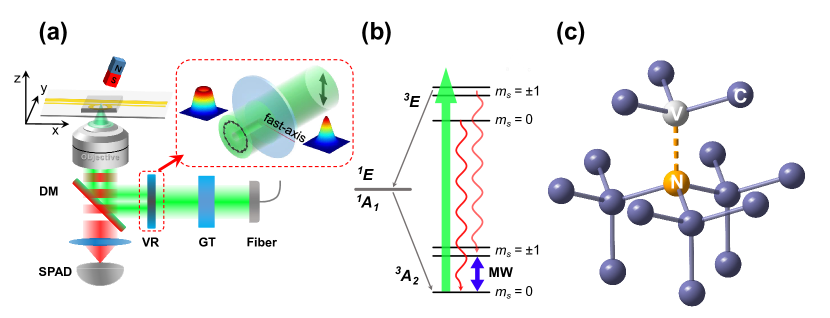
where D=2.87 GHz is zero-field splitting parameter. is the Bohr magneton, is the nuclear magneton. and are the electron spin and nuclear spin g-factor, respectively. In the Hamiltonian, the first term denotes the zero field splitting (ZFS), the second term is the electron spin Zeeman splitting, the third term is the hyper-fine interaction between electron spin and nuclear spin, the fourth term is the nuclear quadrupole splitting (), the last term is the nuclear Zeeman splitting. As shown in Fig.1(b), the sub-levels of the ground state () are degenerate at zero magnetic field. At external magnetic field condition, the sub-levels have Zeeman splitting, and the resonance lines between and are separated around 2.87 GHz. The transitions between the and spin sub-levels of the ground state () can be detected by ODMR.
In contrast to previous work, we employ the azimuthally polarized beam, which is tightly focused by a high numerical-aperture (NA) aplanatic objective lens, to scan the NV centers. The polarization near the focal spot region is inhomogeneous. The electric field vector (E(r)) near focus can be expressed as31
| (2) |
Here is the Bessel function of the first kind with order n. is the position of the focus spot. is the wave number of the light in the medium. In the integral, the upper bound of the polar angle () is determined by the NA of the objective lens. A is the field strength at the pupil aperture. For azimuthally polarized beam, the total field is transverse and we only consider the azimuthal component of the electric field vector near focus region. Its intensity is an on-axis null and annular intensity distribution at all distance from the paraxial focus.
The fluorescence intensity distribution is determined by the interaction between the electric field vector and the excitation dipole of the NV center39, 40, 41. Strain-dependent optical measurement of NV center has indicated that two orthogonal electric dipoles are in the plane perpendicular to the symmetry axis42, which are responsible for the emission fluorescence. The fluorescence intensity distribution by scanning NV center can be written as , where E(r) is the position dependent electric field and the is the excitation dipole vector.
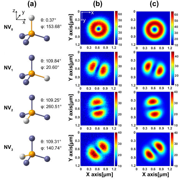
Because of the inhomogeneous transverse polarization components around the focal spot, the scanning confocal image has characteristic intensity pattern that is different from the Gaussian distribution with a linearly polarized beam. The fluorescence pattern with the azimuthally polarized beam is dependent on the three-dimensional orientation of the NV center’s excitation dipole. We simulate this process and calculate the photon pattern numerically. In Fig.2(c), different patterns indicate different oriented NV centers.
The experiment is performed on a purpose-built confocal microscopy system as shown in Fig.1(a) to address single NV center in a type-IIa, single-crystal synthetic bulk diamond. A collimated 532 nm pulse laser beam is passed through the single mode optical fiber and shaped into approximately ideal Gaussian beam. The Gaussian beam is sent through the Glan-Taylor polarizer and produced high-quality linear polarization beam with an extinction ratio greater than 100,000:1. Such a beam is then sent to the Zero-Order Vortex Half-Wave Retarder(m=1) which can generate azimuthally polarized beam with the doughnut-like feature as shown in Fig.1(a). The generated azimuthally polarized beam is then focused on the NV center using an Olympus oil-immersion microscope objective lens (NA=1.40). A piezoelectric transducer (PZT) stage holds the diamond perpendicular to the beam in order to implement the scanning in the transverse x-y plane of the sample. The fluorescence photons ranging from 600 to 800 nm are collected by the same objective lens, and detected by using the single photon avalanche diode (SPAD). The microwave signal (generated by Rohde Schwarz) is amplified (Mini-Circuits ZHL-42W+) and delivered to an impedance-matched copper slotline (0.1 gap and an -type ring in the middle) deposited on a coverslip, and finally coupled to the NV center. A small permanent magnet (south pole) in the vicinity of the diamond generates the static magnetic field to be detected.
| NV1 | NV2 | NV3 | |
|---|---|---|---|
| (x,y) (m) | (16.175, 7.335) | (16.450, 1.920) | (5.346, 7.678) |
| (∘) | 117.62 0.02 | 106.96 0.02 | 102.55 0.01 |
| B (G) | 59.53 0.26 | 59.48 0.35 | 59.56 0.36 |
Experimentally, we scan the diamond using the azimuthally polarized beam with the result shown in Fig.2(b), where four kinds of patterns are all observed and coincident with numerical simulation. To figure out the orientation of NV centers in the laboratory frame, we select four different patterns, which are noted as NV0, NV1, NV2, and NV3. Then we develop an optimization algorithm based on the Nelder-Mead method to determine the angles associated with the scanned patterns. The optimization routine starts from a random state of the angles and minimize the difference between simulation result and experimental pattern by varying the angles iteratively. Note that, there’s still a rotational symmetry of in the azimuth angle, which can be easily broken by using a simple static magnetic field29. Fig.2 shows the final result including polar angle and azimuth angle of the NV centers, where all four patterns match well with experiment.
With all the obervations, we then proceed to demonstrate the vector magnetometer with three different-oriented NV centers. And the full vector information of the field could be reconstructed from the individual measurement results and the NV center orientation. In each measurement, the magnitude of magnetic field, the polar angle between the magnetic field and the NV center axis are obtained by the standard ODMR procedure.
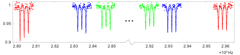
The ODMR spectra lines are usually power broadened by laser and microwave (MW) radiation. We employ the normal Gaussian beam to excite the NV centers and get the ODMR spectra. To obtain the high resolution ODMR spectra, we replace the CW (continuous wave) ODMR process with the pulsed ODMR process using pulsed laser (400 ns) and MW field (electron spin -pulse). By sweeping MW field frequency, we can observe the electron spin transitions from to in ground state (), which are both three peaks owing to the hyper-fine interaction between electron spin and nuclear spin () based on Eq.1. As shown in Fig.3, the middle peaks ( and ) of the three peaks are the transition frequencies of and , respectively. For magnetic field in arbitrary direction, the transition frequencies can be selected to calculate the magnitude according to and the polar angle expressed by 26. Based on the ODMR spectra, we only can get the polar angle between the magnetic field and the NV axis. But the polar angle only tells that the possible orientation of the magnetic field is a cone around the NV center axis as shown in Fig.4(a)-(c).
To completely obtain the information about the magnetic field orientation, we need three different orientation NV centers at least. Here, we select NV1, NV2 and NV3 as magnetic sensors. The fitted results of the polar angle and magnitude for NV1, NV2 and NV3 are shown in Table 1. In theory, the cones around three NV center axes have an intersection, which is the absolute orientation of the magnetic field in laboratory coordinate system as shown in Fig.4. Experimentally, three cones can’t strictly intersect at a point and have deviation in the overlap. The deviation can be from strain of lattice and temperature fluctuation during measurement process. The intersections of three cones form a triangle in unit sphere as shown in the inset of Fig.4(d). To evaluate the direction of the magnetic field, we employ the least square method to get the optimal solution (see Supporting Information). The direction of the magnetic field is with error less than .
3 Conclusion
In conclusion, we propose and demonstrate an efficient way to reconstruct vector information of magnetic field with NV centers in diamond. The optical vortex beam is azimuthally polarized beam which induces an orientation-dependent image pattern when scanning NV centers in a confocal system. With the vortex beam, the orientations of the NV centers in a bulk diamond could be directly determined from the scanning image. Combining with the ODMR spectra, the complete information of the magnetic field including the magnitude and orientation could be reconstructed. Our works provides a calibration-free nano-scale vector magnetometry and can be easily used in NV-based magnetic field sensing and imaging.
The authors are grateful to Heng Shen, FengJian Jiang and Yong Zhou for fruitful discussions. This work is supported by the National Key R&D Program of China (Grants No. 2018YFA0306600, No. 2018YFF01012505 and No. 2018YFF01012500), the National Natural Science Foundation of China (Grants No. 11604069, No. 61805064, No. 11775209, No. 81788101, No. 11761131011 and No. 11904070), the Fundamental Research Funds for the Central Universities, the CAS (Grants No. GJJSTD20170001, No. QYZDY-SSW-SLH004), the Anhui Initiative in Quantum Information Technologies (Grant No. AHY050000).
References
- Degen et al. 2017 Degen, C. L.; Reinhard, F.; Cappellaro, P. Quantum sensing. Reviews of Modern Physics 2017, 89, 035002
- Barry et al. 2020 Barry, J. F.; Schloss, J. M.; Bauch, E.; Turner, M. J.; Hart, C. A.; Pham, L. M.; Walsworth, R. L. Sensitivity optimization for NV-diamond magnetometry. Reviews of Modern Physics 2020, 92, 015004
- Kimball and Budker 2013 Kimball, D. F. J.; Budker, D. Optical Magnetometry; Cambridge University Press, 2013
- Budker and Romalis 2007 Budker, D.; Romalis, M. Optical magnetometry. Nature Physics 2007, 3, 227–234
- Vasyukov et al. 2013 Vasyukov, D.; Anahory, Y.; Embon, L.; Halbertal, D.; Cuppens, J.; Neeman, L.; Finkler, A.; Segev, Y.; Myasoedov, Y.; Rappaport, M. L., et al. A scanning superconducting quantum interference device with single electron spin sensitivity. Nature Nanotechnology 2013, 8, 639–644
- Doherty et al. 2013 Doherty, M. W.; Manson, N. B.; Delaney, P.; Jelezko, F.; Wrachtrup, J.; Hollenberg, L. C. The nitrogen-vacancy colour centre in diamond. Physics Reports 2013, 528, 1–45
- Shi et al. 2015 Shi, F.; Zhang, Q.; Wang, P.; Sun, H.; Wang, J.; Rong, X.; Chen, M.; Ju, C.; Reinhard, F.; Chen, H., et al. Single-protein spin resonance spectroscopy under ambient conditions. Science 2015, 347, 1135–1138
- Van der Sar et al. 2012 Van der Sar, T.; Wang, Z.; Blok, M.; Bernien, H.; Taminiau, T.; Toyli, D.; Lidar, D.; Awschalom, D.; Hanson, R.; Dobrovitski, V. Decoherence-protected quantum gates for a hybrid solid-state spin register. Nature 2012, 484, 82–86
- Abobeih et al. 2019 Abobeih, M.; Randall, J.; Bradley, C.; Bartling, H.; Bakker, M.; Degen, M.; Markham, M.; Twitchen, D.; Taminiau, T. Atomic-scale imaging of a 27-nuclear-spin cluster using a quantum sensor. Nature 2019, 576, 411–415
- Chen et al. 2020 Chen, B.; Hou, X.; Zhou, F.; Qian, P.; Shen, H.; Xu, N. Detecting the out-of-time-order correlations of dynamical quantum phase transitions in a solid-state quantum simulator. Applied Physics Letters 2020, 116, 194002
- Grinolds et al. 2013 Grinolds, M. S.; Hong, S.; Maletinsky, P.; Luan, L.; Lukin, M. D.; Walsworth, R. L.; Yacoby, A. Nanoscale magnetic imaging of a single electron spin under ambient conditions. Nature Physics 2013, 9, 215–219
- Maze et al. 2008 Maze, J. R.; Stanwix, P. L.; Hodges, J. S.; Hong, S.; Taylor, J. M.; Cappellaro, P.; Jiang, L.; Dutt, M. G.; Togan, E.; Zibrov, A., et al. Nanoscale magnetic sensing with an individual electronic spin in diamond. Nature 2008, 455, 644–647
- Chaudhry 2015 Chaudhry, A. Z. Detecting the presence of weak magnetic fields using nitrogen-vacancy centers. Physical Review A 2015, 91, 062111
- Wang et al. 2015 Wang, P.; Yuan, Z.; Huang, P.; Rong, X.; Wang, M.; Xu, X.; Duan, C.; Ju, C.; Shi, F.; Du, J. High-resolution vector microwave magnetometry based on solid-state spins in diamond. Nature Communications 2015, 6, 1–5
- Glenn et al. 2018 Glenn, D. R.; Bucher, D. B.; Lee, J.; Lukin, M. D.; Park, H.; Walsworth, R. L. High-resolution magnetic resonance spectroscopy using a solid-state spin sensor. Nature 2018, 555, 351–354
- Wang et al. 2019 Wang, P.; Chen, S.; Guo, M.; Peng, S.; Wang, M.; Chen, M.; Ma, W.; Zhang, R.; Su, J.; Rong, X., et al. Nanoscale magnetic imaging of ferritins in a single cell. Science Advances 2019, 5, eaau8038
- Degen 2008 Degen, C. Scanning magnetic field microscope with a diamond single-spin sensor. Applied Physics Letters 2008, 92, 243111
- Casola et al. 2018 Casola, F.; van der Sar, T.; Yacoby, A. Probing condensed matter physics with magnetometry based on nitrogen-vacancy centres in diamond. Nature Reviews Materials 2018, 3, 1–13
- Robledo et al. 2011 Robledo, L.; Bernien, H.; Van Der Sar, T.; Hanson, R. Spin dynamics in the optical cycle of single nitrogen-vacancy centres in diamond. New Journal of Physics 2011, 13, 025013
- Chakraborty et al. 2017 Chakraborty, T.; Zhang, J.; Suter, D. Polarizing the electronic and nuclear spin of the NV-center in diamond in arbitrary magnetic fields: analysis of the optical pumping process. New Journal of Physics 2017, 19, 073030
- Chen et al. 2019 Chen, B.; Geng, J.; Zhou, F.; Song, L.; Shen, H.; Xu, N. Quantum state tomography of a single electron spin in diamond with Wigner function reconstruction. Applied Physics Letters 2019, 114, 041102
- Xu et al. 2019 Xu, N.; Tian, Y.; Chen, B.; Geng, J.; He, X.; Wang, Y.; Du, J. Dynamically Polarizing Spin Register of N-V Centers in Diamond Using Chopped Laser Pulses. Physical Review Applied 2019, 12, 024055
- Le Sage et al. 2013 Le Sage, D.; Arai, K.; Glenn, D. R.; DeVience, S. J.; Pham, L. M.; Rahn-Lee, L.; Lukin, M. D.; Yacoby, A.; Komeili, A.; Walsworth, R. L. Optical magnetic imaging of living cells. Nature 2013, 496, 486–489
- Schirhagl et al. 2014 Schirhagl, R.; Chang, K.; Loretz, M.; Degen, C. L. Nitrogen-vacancy centers in diamond: nanoscale sensors for physics and biology. Annual Review of Physical Chemistry 2014, 65, 83–105
- McGuinness et al. 2011 McGuinness, L. P.; Yan, Y.; Stacey, A.; Simpson, D. A.; Hall, L. T.; Maclaurin, D.; Prawer, S.; Mulvaney, P.; Wrachtrup, J.; Caruso, F., et al. Quantum measurement and orientation tracking of fluorescent nanodiamonds inside living cells. Nature Nanotechnology 2011, 6, 358–363
- Balasubramanian et al. 2008 Balasubramanian, G.; Chan, I.; Kolesov, R.; Al-Hmoud, M.; Tisler, J.; Shin, C.; Kim, C.; Wojcik, A.; Hemmer, P. R.; Krueger, A., et al. Nanoscale imaging magnetometry with diamond spins under ambient conditions. Nature 2008, 455, 648–651
- Maertz et al. 2010 Maertz, B.; Wijnheijmer, A.; Fuchs, G.; Nowakowski, M.; Awschalom, D. Vector magnetic field microscopy using nitrogen vacancy centers in diamond. Applied Physics Letters 2010, 96, 092504
- Pham et al. 2012 Pham, L. M.; Bar-Gill, N.; Le Sage, D.; Belthangady, C.; Stacey, A.; Markham, M.; Twitchen, D.; Lukin, M. D.; Walsworth, R. L. Enhanced metrology using preferential orientation of nitrogen-vacancy centers in diamond. Physical Review B 2012, 86, 121202
- Weggler et al. 2020 Weggler, T.; Ganslmayer, C.; Frank, F.; Eilert, T.; Jelezko, F.; Michaelis, J. Determination of the Three-Dimensional Magnetic Field Vector Orientation with Nitrogen Vacany Centers in Diamond. Nano Letters 2020, 20, 2980–2985
- Alegre et al. 2007 Alegre, T. P. M.; Santori, C.; Medeiros-Ribeiro, G.; Beausoleil, R. G. Polarization-selective excitation of nitrogen vacancy centers in diamond. Physical Review B 2007, 76, 165205
- Zhan 2009 Zhan, Q. Cylindrical vector beams: from mathematical concepts to applications. Advances in Optics and Photonics 2009, 1, 1–57
- Maurer et al. 2007 Maurer, C.; Jesacher, A.; Fürhapter, S.; Bernet, S.; Ritsch-Marte, M. Tailoring of arbitrary optical vector beams. New Journal of Physics 2007, 9, 78
- Kimura et al. 1995 Kimura, W.; Kim, G.; Romea, R.; Steinhauer, L.; Pogorelsky, I.; Kusche, K.; Fernow, R.; Wang, X.; Liu, Y. Laser acceleration of relativistic electrons using the inverse Cherenkov effect. Physical Review Letters 1995, 74, 546
- Zhan 2004 Zhan, Q. Trapping metallic Rayleigh particles with radial polarization. Optics Express 2004, 12, 3377–3382
- Huang et al. 2012 Huang, L.; Guo, H.; Li, J.; Ling, L.; Feng, B.; Li, Z.-Y. Optical trapping of gold nanoparticles by cylindrical vector beam. Optics Letters 2012, 37, 1694–1696
- Dorn et al. 2003 Dorn, R.; Quabis, S.; Leuchs, G. Sharper focus for a radially polarized light beam. Physical Review Letters 2003, 91, 233901
- Cardano et al. 2012 Cardano, F.; Karimi, E.; Slussarenko, S.; Marrucci, L.; de Lisio, C.; Santamato, E. Polarization pattern of vector vortex beams generated by q-plates with different topological charges. Applied Optics 2012, 51, C1–C6
- Ye et al. 2019 Ye, Y.-H.; Dong, M.-X.; Yu, Y.-C.; Ding, D.-S.; Shi, B.-S. Experimental realization of optical storage of vector beams of light in warm atomic vapor. Optics Letters 2019, 44, 1528–1531
- Karedla et al. 2015 Karedla, N.; Stein, S. C.; Hähnel, D.; Gregor, I.; Chizhik, A.; Enderlein, J. Simultaneous measurement of the three-dimensional orientation of excitation and emission dipoles. Physical Review Letters 2015, 115, 173002
- Dolan et al. 2014 Dolan, P. R.; Li, X.; Storteboom, J.; Gu, M. Complete determination of the orientation of NV centers with radially polarized beams. Optics Express 2014, 22, 4379–4387
- Patra et al. 2004 Patra, D.; Gregor, I.; Enderlein, J. Image analysis of defocused single-molecule images for three-dimensional molecule orientation studies. The Journal of Physical Chemistry A 2004, 108, 6836–6841
- Epstein et al. 2005 Epstein, R.; Mendoza, F.; Kato, Y.; Awschalom, D. Anisotropic interactions of a single spin and dark-spin spectroscopy in diamond. Nature Physics 2005, 1, 94–98