Impedance Matching in an Elastic Actuator
Abstract
We optimize the performance of an elastic actuator consisting of an active core in a host which performs mechanical work on a load. The system, initially with localized elastic energy in the active component, relaxes and distributes energy to the rest of the system. Using the linearized Mooney-Rivlin hyperelastic model in a cylindrical geometry and assuming the system to be overdamped, we show that the value of the Young’s modulus of the impedance matching host which maximizes the energy transfer from the active component to the load is the geometric mean of Young’s moduli of the active component and the elastic load. This is similar to the classic results for impedance matching for maximizing the transmittance of light propagating through dielectric media.
Keywords: impedance matching, elastic actuator, geometric mean
1 Introduction
When light propagates through a planar interface between two perfect dielectrics, a portion of the light is reflected and the rest is transmitted. To minimize the reflectance in medium 1 with refractive index , or equivalently, to maximize the transmitted light to medium 3 with refractive index , one can insert an index matching layer with refractive index between the two media. Furthermore, the reflectance is zero if the thickness of the index matching medium is one quarter of the wavelength [1]. One can apply the same principle to achieve the perfect sound transmittance by positioning a quarter wavelength impedance matching layer with index , with the mass density and the speed of sound [2]. Impedance matching techniques are widely used in applications involving elastic wave propagation as well as in electronics [3, 4, 5].
The case of a head-on elastic collision of two rigid balls with masses and offers an interesting analogy. To maximize the energy transfer from , which has nonzero initial energy , to , which has zero initial energy, one can position a rigid ball with mass and zero initial energy, in between the two balls [6].
The similarity of these very different physical phenomena is that energy is conserved throughout the process: energy is either reflected or transmitted. The transmitted energy can be increased when an impedance matching medium is inserted. The fraction of reflected energy in case of normal incidence/collision between two media/balls, is given by,
| (1) |
where for the case of light propagation through an interface, and for elastic collision of rigid balls. The transmitted energy is given by . If there are three media in series, the fraction of transmitted energy from medium to medium , via medium , is given by
| (2) |
Here the interference due to multiple reflections has been neglected in Eq. (2), and media and are assumed to be semi-infinite in the propagation direction. Exact expression including the dependence on the thickness of layer in the wave propagation case can be found in Refs. [1, 2]. Upon maximizing in Eq. (2) with respect to , one arrives immediately at,
| (3) |
thus the value of which maximizes the energy transmission from to is the geometric mean of and . Mechanical impedance is a measure of effectiveness of a force in producing velocity. Remarkably, one can optimize certain energy transfer processes by inserting an index matching component.
In this paper, we study a related problem of optimizing the transfer of elastic energy from one elastic body to another via an impedance matching element.
Specifically, we consider three elastic bodies: body is the active element with stored elastic energy, contained in body , the host, which is the impedance matching element and body is the load to which we wish to transfer elastic energy. For simplicity, we use cylindrical symmetry in our example. All three bodies are isotropic, homogeneous and uniform and share the same axis of symmetry; body is a cylinder, while bodies and are annuli. The geometry is shown in Fig. 1.
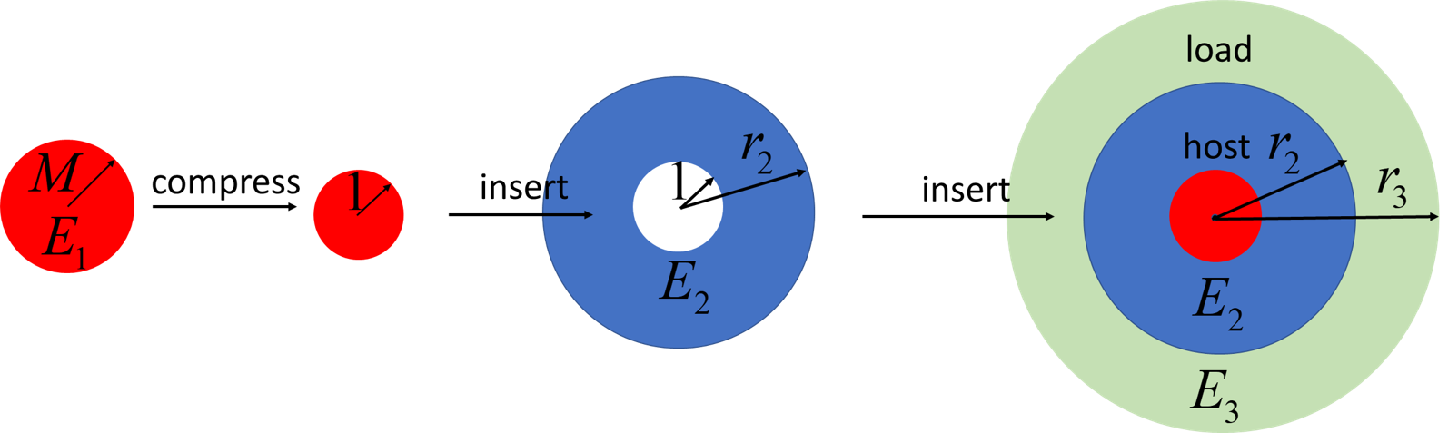
We begin with the host, body , which is an annulus with a cylindrical cavity. Initially it is stress free. We then take another elastic body, with a different elastic modulus, which is too large (or too small) to fit fully into the cavity of the host. We then compress (or stretch) this body until its shape is the same as that of the cavity. This is the active body . We then place the active body, keeping its shape fixed, into the cavity of the host. The third body is the load; an annulus whose cavity can perfectly accommodate the host. Finally, we place the host with the active body into the cavity of the load, as indicated in Fig. 1. The system is then allowed to relax.
When released, the internal stored elastic energy of the active medium will do mechanical work on the load. The situation illustrated here is similar to a light driven actuator, where the photoactive part of the system expands or shrinks on illumination, distributing stress to the surrounding medium, causing a deformation. The system can then do mechanical work, say expand against a pressure. Given the properties of the actuator and the load, can we maximize the work by choosing a suitable host material? Below, we present a mathematical model of the deformation of elastic media in a cylindrical geometry, and determine Young’s modulus of the impedance matching host which maximizes the energy transferred to the load. The results suggest a strategy for optimizing the performance of an elastic actuator.
We remark that the similar analysis cannot be carried out in a spherical geometry with volume conserving materials, since an incompressible sphere cannot be radially deformed.
2 Mathematical Model
We use Lagrangian mechanics to model the system. We start with the incompressible Mooney-Rivlin’s hyperelastic model, in which the energy density of an elastic material is a linear combination of invariants of the left Cauchy-Green deformation tensor [7, 8]
| (4) |
where are principal stretches, and due to incompressibility. Assuming the deformations are small, expanding in terms of and , we get,
| (5) |
We further assume that all deformations have cylindrical symmetry, and denote the position of a point in body . Here and are the Lagrangian coordinates denoting the position of mass points in the undeformed system. Then the principal stretches are given by
| (6) |
where is along the radial, along the azimuthal and along the direction. In terms of , we can express the elastic energy density in the linear regime as
| (7) |
where is Young’s modulus and .
The energy per length in the direction of the system consisting of the elastic bodies , and is given by
| (8) |
where the radius of the central hole in the undeformed host is taken to be unity, is the radius of the pre-strained active core, and are the outer radii of the host and the load, respectively.
Minimizing the total energy gives the Euler-Lagrange equation describing the deformation. All three parts, active core, host, and load, share the same form of the equation, which is given by
| (9) |
It admits the solution
| (10) |
where and , , are determined by the interface and boundary conditions, which are detailed below.
The continuity condition for displacements across the interfaces are given by,
| (11) | |||||
| (12) | |||||
| (13) |
In addition, the normal stresses are continuous across the two interfaces, which are
| (14) | |||||
| (15) |
We would need another boundary condition at the outmost boundary to complete the set of equations to be solved.
2.1 Zero-strain boundary condition
If the outer boundary of the load is fixed, boundary condition at reads as,
| (16) |
Together with the five interface conditions, these six linear equations determine the six unknowns, and uniquely, and they are functions of and , . Since the solutions are rather lengthy algebraic expressions, we omit them and only report the final optimization results.
We are interested in the transfer of elastic energy from the active core to the outside load. We therefore ask: what value of Young’s modulus of the host material will maximizes the transfer of energy from the active core to the load? Maximizing the energy in the load transferred from the active core is equivalent to maximizing the displacement of inner radius of the load . We note that . Taking the derivative of with respect to , we obtain,
| (17) |
In the case of , the load is infinitely large, we have . This results is a reminiscent of an equivalent result for refractive indices in the case of impedance matching for light propagation in 1D media.
2.2 Zero-stress boundary condition
In this case, the outer boundary of the load is free to move, and the boundary condition at is given by,
| (18) |
Together with the interface equations, the six unknowns, and are uniquely determined. Again, we are interested in the energy transfer from the active core to the load, and we ask the same question as in the zero-strain case: what value of Young’s modulus of the host material will maximize the transfer of energy from the active core to the load? Although it is not obvious, maximizing the energy in the load transferred from the active core is equivalent to maximizing the displacement of outer radius of the load . Taking the derivative of with respect to , we obtain
| (19) |
Again the result is a geometric mean of Young’s modulus of medium 1 and 3, multiplied with a geometric factor depending on radii of components. In the case when ,
Figure 2 demonstrates the maximum energy transferred to the load from the active material occurs when the impedance matching modulus is given by Eq. (17) or (19) at zero-strain or zero-stress boundary condition, respectively.
(a)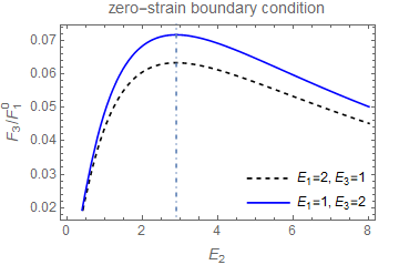 (b)
(b)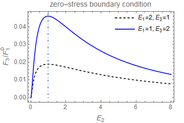
2.3 Reflectance and transmittance
We finally look at the problem from the reflectance and transmittance point of view and build a connection with the case of light propagation. Consider the active core and the load only, with fixed outer boundary condition. The active core initially has stored elastic energy; it is subsequently released and transfers some of its stored energy to the load. We define the quantities
| (20) |
as reflectance and transmittance, where is the final equilibrium energy for each component and is the initial energy of the active core. We remark that the total energy of the system in its final equilibrium state is less than the initial energy of the active core due to dissipation. In the limit that the outside radius of the load goes to infinity, we obtain
| (21) |
Upon inserting an impedance matching host between the active core and the load, the transmittance from the active core to the load becomes
| (22) |
Maximizing over gives
| (23) |
We have recovered the results from above via an energy transfer point of view in the limit when the size of the load goes to infinity. The main difference between our case and light propagation case lies in that the energy is not conserved in the former but is conserved in the latter case. It suggests that energy conservation is not a key requirement in impedance matching mechanisms.
3 Conclusion
In this work, we are interested in the work done by an active material on the materials surrounding it. Specifically, we have an initially nonequilibrium elastic system with all the energy stored in one part, and the system is then allowed to relax. We look for ways to improve the efficiency in transferring energy to other parts of the system at equilibrium. To do so, we analyzed a composite system consisting an active elastic material, a host, and a load. We found that in the cylindrical geometry, the transferred energy from the active material to the load can be maximized by tuning Young’s modulus of the impedance matching host material. The analysis was done using the linearized Mooney-Rivlin hyperelastic model and assuming incompressibility of all components. We further assumed that the system was overdamped and elastic wave propagation was not considered. The active material located at the center of the host, when actuated, transfers stored energy to the load through the host. We have considered two cases where the outer boundary of the load is fixed and where it is free. Young’s modulus of the host material which maximizes the energy transfer is found to be the geometric mean of the moduli of the active material and the load, multiplied by a geometric factor which depends on the radii of the components. In the limit when the size of the load goes to infinity, Young’s modulus for the host is simply the geometric mean of the moduli of the active material and the load. This coincides with the classical result from impedance matching in the case of light propagating through dielectric media. Although the model is simplified with idealized geometry and is in the small strain limit, we anticipate the results will help optimize the performance of photomechanical materials by using an impedance matching host between the active material and the load.
Acknowledgment
This work was supported by the Office of Naval Research [ONRN00014-18-1- 2624]
References
- [1] Stratton, J.A., 1941. Electromagnetic Theory, McGrow-Hill Book Company. Inc., New York, and London.
- [2] Kim, Y.H., Sound propagation: an impedance based approach. John Wiley & Sons, (2010).
- [3] Chen, S., Zhang, Y., Hao, C., Lin, S. and Fu, Z., 2014. Functionally graded materials for impedance matching in elastic media. Physics Letters A, 378(1-2), pp.77-81.
- [4] Rahimzadeh, T., Arruda, E.M. and Thouless, M.D., 2015. Design of armor for protection against blast and impact. Journal of the Mechanics and Physics of Solids, 85, pp.98-111.
- [5] Rathod, V.T., 2019. A review of electric impedance matching techniques for piezoelectric sensors, actuators and transducers. Electronics, 8(2), p.169.
- [6] Santos, J., de Oliveira, B.P. and Nelson, O.R., Impedance of rigid bodies in one-dimensional elastic collisions. Revista Brasileira de Ensino de FÃ-sica, 34(1), 1-4 (2012).
- [7] Mooney, M., 1940, A theory of large elastic deformation, Journal of Applied Physics, 11(9), pp. 582-592.
- [8] Rivlin, R. S., 1948, Large elastic deformations of isotropic materials. IV. Further developments of the general theory, Philosophical Transactions of the Royal Society of London. Series A, Mathematical and Physical Sciences, 241(835), pp. 379-397.