Quasi-phasematching in a poled Josephson traveling-wave parametric amplifier with three-wave mixing
Abstract
We develop the concept of quasi-phasematching (QPM) by implementing it in the recently proposed Josephson traveling-wave parametric amplifier (JTWPA) with three-wave mixing (3WM). The amplifier is based on a ladder transmission line consisting of flux-biased radio-frequency SQUIDs whose nonlinearity is of -type. QPM is achieved in the 3WM process, (where , , and are the pump, signal, and idler frequencies, respectively) due to designing the JTWPA to include periodically inverted groups of these SQUIDs that reverse the sign of the nonlinearity. Modeling shows that the JTWPA bandwidth is relatively large (ca. ) and flat, while unwanted modes, including , , , etc., are strongly suppressed with the help of engineered dispersion.
Due to vanishingly small losses and an ultimately quantum level of internal noise, Louisell1961 cryogenic traveling-microwave parametric amplifiers based on the kinetic inductance of superconducting wires Eom2012 ; Vissers2016 ; Malnou2021 and Josephson junctions Macklin2015 ; White2015 ; Planat2020 ; Ranadive2021 are considered highly useful quantum devices that can be applied in precision quantum measurements, photon detection, quantum communication and quantum computing. Wallraff2004 ; Devoret2013 In comparison to their cavity-based counterparts, Movshovich1990 ; Castellanos-Beltran2007 ; Yamamoto2008 traveling-wave parametric amplifiers have the advantages of a wider bandwidth and a larger dynamic range. However, realization of phase matching that is sufficient for ensuring large (ideally, exponential Agrawal2007 ) flat signal gains in a wide bandwidth remains the greatest challenge when designing such amplifiers. Macklin2015 ; White2015 ; Planat2020 ; OBrien2014 ; Bell-Samolov2015 ; WenyuanZhang2017 ; Ranadive2021
Josephson traveling-wave parametric amplifiers (JTWPAs) have the architecture of a transmission line with discrete elements. Mohebbi2009 Their performance is normally based on a Kerr-like nonlinearity, i.e., a Josephson relation between a small current and a small flux of the form , where is the inverse inductance, is normalized flux quantum, and is the Kerr coefficient. Yaakobi2013 These amplifiers are operated in a four-wave mixing (4WM) regime wherein the pump (), signal (), and idler () frequencies obey the relation . However, here, it is difficult to fulfill the phase-matching relation for corresponding wavenumbers, , in a wide range of frequencies and pump powers. Specifically, the Kerr effect causes unwanted self-phase modulation (SPM) and cross-phase modulation (XPM) of waves because of the intensity-dependent phase velocities leading to phase shifts. Agrawal2007 This leads to imperfect phase matching, , which can only be improved by means of dispersion engineering. This can be done, for example, by applying resonant phase matching White2015 ; Macklin2015 ; OBrien2014 or by inverting the Kerr coefficient sign, . Bell-Samolov2015 ; Ranadive2021
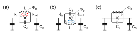
Recently, superconducting elements that possess widely tunable non-centrosymmetric nonlinearity of the -type have been proposed. Such elements (see Fig. 1) include either non-hysteretic radio-frequency SQUIDs (rf-SQUIDs) Zorin2016 or asymmetric multijunction SQUIDs, i.e., so-called superconducting nonlinear asymmetric inductive elements (SNAILs). Frattini2017 ; Zorin2017 An appropriate magnetic flux applied to these SQUIDs allows the current-flux relation to be adjusted to fit the form
| (1) |
where coefficient is the electrical analog of the susceptibility tensor in the optics. Agrawal2007 Formula (1) provides the means for designing Kerr-free () JTWPAs with pure three-wave mixing (3WM), . Zorin2016 ; Zorin2017 ; Miano2018 Here, the pump frequency favorably lies outside the signal band, .
Another remarkable property of 3WM is the absence of SPM and XPM effects. Hence, for a sufficiently small dispersion, the phase-matching condition, , can be met in a wide frequency range. The dispersion relation in the ladder-type transmission line is Zorin2019
| (2) |
where is the wavenumber normalized on the reverse size of elementary cell and the frequencies and (see notations in Fig. 1) are the SQUID plasma frequency and the line cutoff frequency, respectively. Thus, the condition of small dispersion reads .
In general, mixing of the signal and the pump using the nonlinearity given by Eq. (1) results not only in the idler wave being generated with difference frequency but also in waves with frequencies above , including , , . Moreover, for vanishingly small dispersion, phase-matching conditions for these accompanying processes may also be met. In the original concept of the parametric amplifier with 3WM, Tien1958 ,Cullen1960 these waves were excluded, so their effects on the basic waves were not considered. However, later analysis showed Erickson2017 ; Zorin2019 ; Dixon2020 that these modes not only absorb pump energy (in accordance with the Manley-Rowe relations Manley-Rowe1956 ), but also interact with signal and idler waves, causing notable signal-rise undulation. Zorin2019 As a result, premature pump depletion and irregular dependence of the gain on the signal frequency and pump power were observed in both the simulations Dixon2020 and the experiment. Zorin2017 ; Miano2018
A straightforward method of suppressing the propagation of unwanted high-frequency modes is to reduce the cutoff frequency in such a way that . However, this approach has several drawbacks: First, because the wavelength is only about the size of 10 cells, the discreteness of the line becomes critical; thus, its transmission and, hence, the gain may exhibit notable ripples. Second, in order to keep the impedance unchanged, i.e., , both the inductance and the ground capacitance should be increased; this is possible only by increasing their physical sizes, which may entail difficulties in fabricating the circuit on a standard chip. Third, the maximum pump power is ; Zorin2016 thus, a small value of will yield a small and, hence, cause pump depletion at a rather low signal power.
To solve this problem, we first engineered a reasonably large dispersion. By setting the SQUID plasma frequency slightly above the double pump frequency, , which is done by increasing the SQUID capacitance , a phase mismatch for unwanted modes, , , and (all of which are between and ) can be made sufficiently large in accordance with formula (2). The unavoidable phase mismatch for basic 3WM, , is not dramatically large in this case, although it depends on the signal frequency . Zorin2019 For example, for , the mismatch is at its maximum, . This value corresponds to a reasonably large coherence length of cells. In principle, this mismatch can be improved by applying either resonator phase-matching OBrien2014 ; White2015 ; Macklin2015 ; Dolata2020 or periodic loading of the line. Eom2012 ; Erickson2017 ; Malnou2021
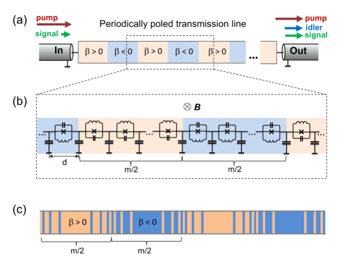
In this Letter, however, we use so-called quasi-phasematching (QPM), Armstrong1962 ; Boyd2008 whose possible implementation in our JTWPA is outlined in Fig. 2. QPM was originally exploited in optical devices, including parametric amplifiers, Charbonneau-Lefort2008 parametric oscillators, Byer1997 second-harmonic generators, Fejer1992 ; Yamada1993 and spontaneous parametric down-converters. Fiorentino2007 These devices were based on nonlinearity in a poled optical material like LiNbO3.
The core operating principles of QPM are as follows. After passing coherence length each time the signal wave is about to begin to decrease (as a consequence of the wavenumber mismatch), a reversal of the -sign occurs, which changes the signal phase by and allows the wave amplitude to continue to grow. When another phase shift has accumulated, the constant-sign domain is reversed again, and so on. Thus, due to the periodic inversion of the orientation (poling) of the LiNbO3 crystal, an effective compensation of the phase mismatch in 3WM is possible. Boyd2008
The mechanism of QPM can be illustrated using simplified coupled-mode equations (CMEs) Agrawal2007 for slowly varying complex amplitudes of the signal and idler waves, and , respectively, which are coupled to the pump wave with amplitude . The corresponding signal (idler) wave is given by the expression , where is a continuous coordinate that is normalized on cell size . Thus, the superconductor phase on the -th node at takes the value . Zorin2016 Treating the pump as undepleted, , the CMEs for Kerr-free () 3WM read
| (3) | |||
| (4) |
The peculiarity of these otherwise standard Agrawal2007 equations is the presence of modulation term , a periodic function with a period of . This function takes only binary values, i.e., 1 or , and thus determines the sign of . To capture the QPM effect, we approximate the function by the dominant (first) term in its Fourier series expansion, Byer1997 i.e., . Then, the exponent entered on the right-hand side of Eqs. (3,4), takes the form
| (5) |
Choosing a poling period in such a way that , i.e., the actual QPM condition, the first (fast oscillating) term on the right-hand side of Eq. (5) can be omitted as its integral effect is apparently small, while the second term, , enables efficient parametric mixing. As a result, an exponentially increasing solution, , in which the exponential gain factor is , takes place on a much larger scale than . Boyd2008 The effective value of the nonlinear coefficient is . If the function has a meander shape with a 50% duty cycle, the Fourier coefficient is , yielding . Boyd2008 The resulting reduction in gain can be compensated by applying a somewhat larger pump amplitude and/or an increasing length .
In contrast to the optical-material QPM technologies, Armstrong1962 ; Byer1997 ; Fiorentino2007 the rf-SQUID-based transmission line can be poled in a relatively simple way. A perpendicular magnetic field B creates a magnetic flux that is applied to each SQUID; here, is the loop area. Assuming without loss of generality that , one obtains an anticlockwise direction for the circulating current independently of the SQUID configuration (as shown in Figs. 1(a) and 1(b)). Then, defining the constant phase drop on the Josephson junction as , we arrive at an rf-SQUID equation for the magnetic flux Likharev1986 in the form
| (6) |
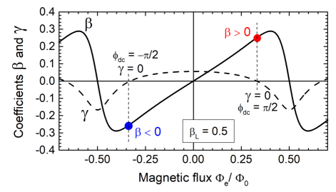
where the sign () corresponds to the configuration shown in Fig. 1(a) (1(b)). A change in the sign of the right-hand side of this equation is equivalent to a change of (or, equivalently, a virtual flip of the magnetic field B). As a result, the optimal phase drop, , which ensures both a zero Kerr coefficient (even periodic function of flux ) and nearly the maximum of coefficient (odd periodic function of ), changes its value, (see Fig. 3). Thus, the sign of nonlinearity constant is flipped, .
To demonstrate the efficiency of the QPM concept for JTWPA with 3WM, we modeled the circuit with the architecture shown in Fig. 2, neglecting possible small losses. We designed a sufficiently low plasma frequency , i.e., . For the analysis of this circuit, we used the set of six CMEs Zorin2021 (the so-called CME-2 set Dixon2020 ), which takes into consideration all significant modes with frequencies below the actual transmission threshold of , i.e., and , and thus describes all relevant mixing processes involving large pump. The set of these equations was numerically solved Zorin2021 by means of the standard Runge-Kutta method. The modeling showed the maximum cross-gain for modes and was safely smaller than the direct signal gain. The pump power converted into the second harmonic, , was much less than 1%.
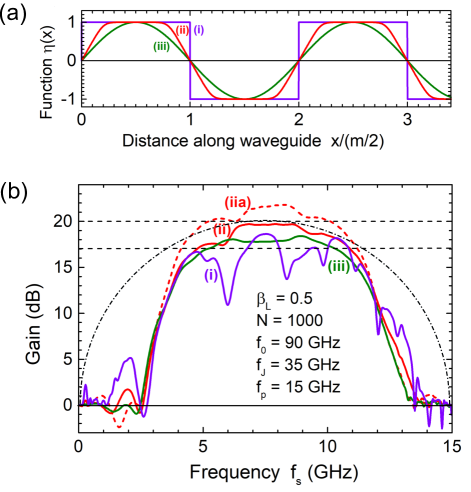
Figure 4(a) shows three types of nonlinearity profiles that have similar periods . This set includes (i) a meander with a 50% duty cycle, i.e., (violet curve); (ii) a tapered meander (widely used in optics for reducing the gain ripple Charbonneau-Lefort2008 ), whose positive half-period is described in our case by the formula
| (7) |
with fixed parameter values, and (red curve); and (iii) a sinusoidal profile, (green curve). To implement shapes (ii) and (iii), they were ”digitized” using pulse-width modulation, Zorin2021 resulting in a variable density of -flips per unit length. Huang2006 The transmission line poled in this fashion is schematically shown in Fig. 2(c).
The signal gain in JTWPA with and , which is calculated for poling profiles (i)-(iii), is shown in Fig. 4(b) as a function of frequency. The pump frequency and the line characteristic frequencies were chosen in such a way that and , which yielded a relatively large chromatic dispersion (see Eq. (2)) and thus a sufficiently large phase mismatch for unwanted high-frequency modes, and . As a result, the coherence lengths for these waves, assuming , were and , respectively. (By comparison, the pump wavelength was .) The phase mismatch for the basic 3WM process was found to be , which yielded a sufficiently large coherence length, . Thus, the designed value of the poling period, , amounted to 448.
The maximum gain of 20 dB, which was achieved for QPM profile of type (ii) at , only roughly corresponds to the theoretical value for QPM gain, whose formula is valid for . Taking into account the effective value of the nonlinear coefficient, , the exponential gain factor is Zorin2016
| (8) |
which yields a signal gain dB dB. This overestimate can be explained by the fact that the number of poling periods accommodated on the full length of our transmission line is not sufficiently large, . Thus, obvious undulations of the growing signal that were clearly seen in our simulations (see such plots, e.g., in Fig. 2.4.2 in Ref. Boyd2008, ), are significant on this scale. However, little increase in the signal gain in such a short transmission line is still possible at a small quasi-phase mismatch, (see dashed red curve in Fig. 4(b) calculated for a tapered meander with a period of ).
Comparison of the gains obtained for different QPM profiles (see Fig. 4(b)) shows that tapering of the profile leads to an appreciable reduction in rippling (see curves (ii) and (iii)). Although the sinusoidal profile (iii) ensures the smoothest possible frequency dependence, the gain level at a similar length and the similar pump amplitude is somewhat smaller (ca. dB) than for the tapered meander (ii) having larger . Thus, exploiting profile (ii) seems to be a good trade-off between maximum gain and smoothness of spectrum. The resulting 3 dB bandwidth is ca. (cf. with the figure for ideal 3WM amplifier of Tien1958 ; Cullen1960 ). For the given circuit parameters, the signal bandwidth is about 6 GHz.
In conclusion, we applied the optical QPM concept to a parametric amplifier for traveling microwaves, designed a poled superconducting transmission line, and demonstrated its efficiency by modeling. We showed that poling in this JTWPA with 3WM can be realized using a simple architecture with periodically inverted groups of identical rf-SQUIDs in a uniform magnetic field. Modeling using CMEs showed that this JTWPA can have a relatively large gain over its wide bandwidth. Moreover, the QPM approach can also be applied to JTWPAs with 3WM based on SNAILs (Fig. 1(c)). Finally, periodic inverting of every second rf-SQUID (or SNAIL) creates a simple design of the transmission line with a fully suppressed nonlinearity of the -type () and widely tunable Kerr coefficient . Bell-Samolov2015 ; WenyuanZhang2017 Such JTWPAs can be operated in pure 4WM regime with a tunable negative value of , which was exploited in a recent study of a JTWPA with reversed Kerr nonlinearity. Ranadive2021
In summary, we believe, that by using the QPM concept in JTWPAs with 3WM, these amplifiers will become the practical devices and support their wide application in quantum technologies.
The author would like to acknowledge useful discussions with T. Dixon, R. Dolata, and C. Kißling. This work was partially funded by the Joint Research Project ParaWave of the European Metrology Programme for Innovation and Research (EMPIR). This project 17FUN10 ParaWave has received funding from the EMPIR programme co-financed by the Participating States and from the European Union Horizon 2020 research and innovation programme.
The data that support the findings of this study are openly available in Zenodo at https://doi.org/10.5281/zenodo.4732453, Ref. 38.
References
- (1) W. H. Louisell, A. Yariv, and A. E. Siegman, Quantum fluctuations and noise in parametric processes. I, Phys. Rev. 124, 1646 (1961).
- (2) B. H. Eom, P. K. Day, H. G. LeDuc, and J. Zmuidzinas, A wideband, low-noise superconducting amplifier with high dynamic range, Nat. Phys. 8, 623 (2012).
- (3) M. R. Vissers, R. P. Erickson, H.-S. Ku, L. Vale, W. Xian, G. C. Hilton, and D. P. Pappas, Low-noise kinetic inductance traveling-wave amplifier using three-wave mixing, Appl. Phys. Lett. 108, 012601 (2016).
- (4) M. Malnou, M. R. Vissers, J. D. Wheeler, J. Aumentado, J. Hubmayr, J. N. Ullom, and J. Gao, A three-wave mixing kinetic inductance traveling-wave amplifier with near-quantum-limited noise performance, PRX Quantum 2, 010302 (2021).
- (5) C. Macklin, K. O’Brien, D. Hover, M. E. Schwartz, V. Bolkhovsky, X. Zhang, W. D. Oliver, and I. Siddiqi, A near-quantum-limited Josephson traveling-wave parametric amplifier, Science 350, 307 (2015).
- (6) T. C. White, J. Y. Mutus, I.-C. Hoi, R. Barends, B. Campbell, Yu Chen, Z. Chen, B. Chiaro, A. Dunsworth, E. Jeffrey, et al., Traveling wave parametric amplifier with Josephson junctions using minimal resonator phase matching, Appl. Phys. Lett. 106, 242601 (2015).
- (7) L. Planat, A. Ranadive, R. Dassonneville, J. P. Martínez, S. Léger, C. Naud, O. Buisson, W. Hasch-Guichard, D. M. Basko, and N. Roch, Photonic-Crystal Josephson Traveling-Wave Parametric Amplifier, Phys. Rev. X 10, 021021 (2020).
- (8) A. Ranadive, M. Esposito, L. Planat, E. Bonet, C. Naud, O. Buisson, W. Guichard, and N. Roch, A reversed Kerr traveling wave parametric amplifier, arXiv:2101.05815.
- (9) A. Wallraff, D. I. Schuster, A. Blais, L. Frunzio, R.-S. Huang, J. Majer, S. Kumar, S. M. Girvin, and R. J. Schoelkopf, Strong coupling of a single photon to a superconducting qubit using circuit quantum electrodynamics, Nature (London) 431, 162 (2004).
- (10) M. H. Devoret and R. J. Schoelkopf, Superconducting circuits for quantum information: An outlook, Science 339, 1169 (2013).
- (11) R. Movshovich, B. Yurke, P. G. Kaminsky, A. D. Smith, A. H. Silver, R. W. Simon, and M. V. Schneider, Observation of zero-point noise squeezing via a Josephson-parametric amplifier, Phys. Rev. Lett. 65, 1419 (1990).
- (12) M. A. Castellanos-Beltran and K. W. Lehnert, Widely tunable parametric amplifier based on a superconducting quantum interference device array resonator, Appl. Phys. Lett. 91, 083509 (2007).
- (13) T. Yamamoto, K. Inomata, M. Watanabe, K. Matsuba, T. Miyazaki, W. D. Oliver, Y. Nakamura, and J. S. Tsai, Flux-driven Josephson parametric amplifier, Appl. Phys. Lett. 93, 042510 (2008).
- (14) G. P. Agrawal, Nonlinear fiber optics (Academic press, San Diego, California, 2007).
- (15) K. O’Brien, C. Macklin, I. Siddiqi, and X. Zhang, Resonant phase matching of Josephson junction traveling wave parametric amplifiers, Phys. Rev. Lett. 113, 157001 (2014).
- (16) M. T. Bell and A. Samolov, Traveling-wave parametric amplifier based on a chain of coupled asymmetric SQUIDs, Phys. Rev. Applied 4, 024014 (2015).
- (17) W. Zhang, W. Huang, M. E. Gershenson, and M. T. Bell, Josephson metamaterial with a widely tunable positive or negative Kerr constant, Phys. Rev. Applied 8, 051001 (2017).
- (18) H. R. Mohebbi and A. H. Majedi, Analysis of series-connected discrete Josephson transmission line, IEEE Trans. Microwave Theory Tech. 57, 1865 (2009).
- (19) O. Yaakobi, L. Friedland, C. Macklin, and I. Siddiqi, Parametric amplification in Josephson junction embedded transmission lines, Phys. Rev. B 87, 144301 (2013).
- (20) A. B. Zorin, Josephson traveling-wave parametric amplifier with three-wave mixing, Phys. Rev. Applied 6, 034006 (2016).
- (21) N. E. Frattini, U. Vool, S. Shankar, A. Narla, K. M. Sliwa, and M. H. Devoret, 3-wave mixing Josephson dipole element, Appl. Phys. Lett. 110, 222603 (2017).
- (22) A. B. Zorin, M. Khabipov, J. Dietel, and R. Dolata, Traveling-wave parametric amplifier based on three-wave mixing in a Josephson metamaterial, 2017 16th International Superconductive Electronics Conference (ISEC), Naples, 2017, pp. 1-3, doi: 10.1109/ISEC.2017.8314196.
- (23) A. Miano and O. A. Mukhanov, Symmetric traveling wave parametric amplifier, IEEE Trans. Appl. Supercond. 29, 1501706 (2019).
- (24) A. B. Zorin, Flux-driven Josephson traveling-wave parametric amplifier, Phys. Rev. Applied 12, 044051 (2019).
- (25) P. K. Tien, Parametric amplification and frequency mixing in propagating circuits, J. Appl. Phys. 29, 1347 (1958).
- (26) A. L. Cullen, Theory of the traveling-wave parametric amplifier, Proc. IEE - Part B: Electron. and Communication Eng. 107, 101 (1960).
- (27) R. P. Erickson and D. P. Pappas, Theory of multiwave mixing within the superconducting kinetic-inductance traveling-wave amplifier, Phys. Rev. B 95, 104506 (2017).
- (28) T. Dixon, J. W. Dunstan, G. B. Long, J. M. Williams, P. J. Meeson, and C. D. Shelly, Capturing complex behaviour in Josephson travelling wave parametric amplifiers, Phys. Rev. Applied 14, 034058 (2020).
- (29) J. M. Manley and H. E. Rowe, Some general properties of nonlinear elements, part 1. General energy relations, Proc. IRE 44, 904 (1956).
- (30) J. A. Armstrong, N. Bloembergen, J. Ducuing, and P. S. Pershan, Interactions between light waves in a nonlinear dielectric, Phys. Rev. 127, 1918 (1962).
- (31) R. W. Boyd, Nonlinear optics (Academic Press, London, 2008).
- (32) M. Charbonneau-Lefort, B. Afeyan, and M. M. Fejer, Optical parametric amplifiers using chirped quasiphase-matching gratings I: practical design formulas, J. Opt. Soc. Am. B 25, 463 (2008).
- (33) R. L. Byer, Quasi-phasematched nonlinear interactions and devices, J. Nonlinear Opt. Phys. Mater. 6, 549 (1997).
- (34) M. M. Fejer, G. A. Magel, D. H. Jundt, R. L. Byer, Quasi-phase-matched second harmonic generation: tuning and tolerance, IEEE J. Quantum Electron. 28, 2631 (1992).
- (35) M. Yamada, N. Nada, M. Saitoh, and K. Watanabe, First-order quasi-phase matched LiNbO3 waveguide periodically poled by applying an external field for efficient blue second-harmonic generation, Appl. Phys. Lett. 62, 435 (1993).
- (36) M. Fiorentino, S. M. Spillane, R. G. Beausoleil, T. D. Roberts, P. Battle, and M. W. Munro, Spontaneous parametric down-conversion in periodically poled KTP waveguides and bulk crystals, Opt. Express 15, 7479 (2007).
- (37) K. K. Likharev, Dynamics of Josephson junctions and circuits (Gordon and Breach, New York, 1986).
- (38) A. B. Zorin, Quasi-phasematching in a Josephson traveling-wave parametric amplifier. Additional information, https://doi.org/10.5281/zenodo.4732453
- (39) J. Huang, X. P. Xie, C. Langrock, R. V. Roussev, D. S. Hum, and M. M. Fejer, Amplitude modulation and apodization of quasiphase-matched interactions, Opt. Lett. 31, 604 (2006).