\ul \xsaveboxPageBGPicture \AtBeginShipout \AtBeginShipoutUpperLeft\xuseboxPageBGPicture
The GRIFFIN Perception Dataset: Bridging the Gap Between Flapping-Wing Flight and Robotic Perception
Abstract
The development of automatic perception systems and techniques for bio-inspired flapping-wing robots is severely hampered by the high technical complexity of these platforms and the installation of onboard sensors and electronics. Besides, flapping-wing robot perception suffers from high vibration levels and abrupt movements during flight, which cause motion blur and strong changes in lighting conditions. This paper presents a perception dataset for bird-scale flapping-wing robots as a tool to help alleviate the aforementioned problems. The presented data include measurements from onboard sensors widely used in aerial robotics and suitable to deal with the perception challenges of flapping-wing robots, such as an event camera, a conventional camera, and two Inertial Measurement Units (IMUs), as well as ground truth measurements from a laser tracker or a motion capture system. A total of 21 datasets of different types of flights were collected in three different scenarios (one indoor and two outdoor). To the best of the authors’ knowledge this is the first dataset for flapping-wing robot perception.
Index Terms:
Data Sets for Robotic Vision; Vision-Based Navigation; Aerial Systems: Perception and Autonomy; Flapping-Wing Robots; Event-Based Cameras.Supplementary Material
The dataset is available at: http:
grvc.us.es/eye-bird-dataset
I Introduction
In the last years, there has been a growing interest in the development of bio-inspired aerial robots. The potential advantages of these platforms, such as flapping-wing robots, over traditional rotary-wing and fixed-wing platforms in terms of energy consumption and safety in populated environments have motivated significant R&D efforts that have resulted in the development of bird-scale platforms (i.e. ornithopters), such as [1], [2], or [3], as well as insect-scale platforms [4]. However, very few of the reported flapping-wing platforms include onboard perception capabilities. We are interested in perception for bird-scale flapping-wing robots, also called ornithopters, which have enough payload capability for onboard sensors and embedded computers. This work has been developed within the GRIFFIN ERC Advanced Grant, which is devoted to the development of ornithopter robots capable of navigating, maneuvering, perching, and manipulating objects in an autonomous manner.
Flapping-wing flight suffers from mechanical vibrations, and wide abrupt movements caused by the lift and thrust generated during downward strokes, which cause limitations in existing perception techniques [5]. Research in flapping-wing robot perception is constrained by the high complexity of these platforms. Besides, although there are a number of datasets for aerial robot perception, none of them provide sensor data collected during flapping-wing flights.
| Dataset | Platform | Event camera | Data type | Scenario | ||
| Mid Air [6] | Multirotor | No | Synthetic | Outdoors | ||
| AU-AIR [7] | Multirotor | No | Real | Outdoors | ||
| V4RL Wide-baseline Place Recognition [8] | Multirotor | No | Synthetic & Real | Outdoors | ||
| EuRoC [9] | MAV | No | Real | Indoors | ||
| Zurich Urban[10] | MAV | No | Real | Outdoors | ||
| Blackbird [11] | MAV | No | Synthetic & Real | Indoors | ||
| UPenn Fast Flight [12] |
|
No | Real | Outdoors | ||
|
Multirotor | Yes | Real |
|
||
|
Multirotor drone racing | Yes | Real |
|
||
| ROSS-LAN [15] |
|
Yes | Synthetic | Indoors | ||
| GRIFFIN Perception |
|
Yes | Real | Indoors & Outdoors |
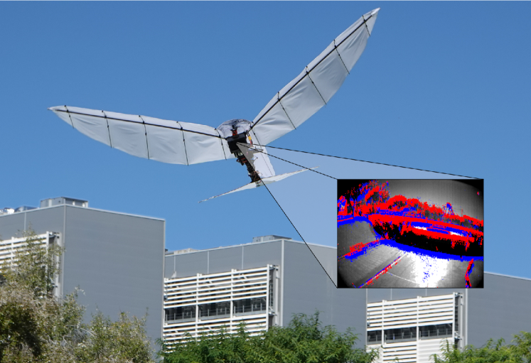
This paper presents a perception dataset for ornithopter robots. It contains measurements gathered from onboard lightweight sensors commonly used in aerial robots and suitable to address the main challenges of perception on board flapping-wing robots: an event camera, a conventional camera, and IMUs. Event cameras have high temporal resolution and dynamic range, which make them very robust against motion blur and lighting conditions. Traditional cameras and IMUs are two of the most widely used sensors in aerial robotics. Besides, the datasets include ground truth measurements from a laser tracker (in outdoor scenarios, see Figure 1) or a motion capture system (in indoors), and ArUco visual markers scattered in the scenario. Three different types of datasets are included: 1) Base datasets, with agile maneuvers that exploit the ornithopter flying capability; 2) ArUco datasets, with ArUco markers in the scenario mapped with ground truth positioning; and 3) People datasets, which provide samples for developing and evaluating object detection techniques based on events and/or visual images. The provided datasets can be useful to develop, tune or evaluate a wide range of image and event-based perception techniques from feature extraction and odometry to object detection, semantic segmentation or SLAM, among others.
The rest of the paper is organized as follows. Section II summarizes the main works in the topics addressed in the paper. The flapping-wing platform and sensors used to collect the dataset are presented in Section III. The sensor data format is given in Section IV. Section V describes the dataset collection and evaluation. Finally, Section VI concludes the paper and highlights the main future research steps.
II Related Work
In recent years, a wide variety of drone datasets have been introduced for robotic perception tasks, see e.g., [6, 8, 7, 9, 10, 11, 12]. The work in [6] presents Mid-Air, a large synthetic dataset of quadcopters flying in unstructured environments that includes data from different scenarios and climate conditions using the Airsim simulator. The work in [8] provides a dataset including real and photo-realistic synthetic data to evaluate place recognition methods with respect to viewpoint tolerance. The AU-AIR dataset [7] presents annotated data of traffic surveillance onboard an Unmanned Aerial Vehicle (UAV) in addition to data from camera, GPS, and IMU. A summary of the main reported datasets for aerial robot perception is shown in Table I.
Some of the released datasets focus specifically on Micro Aerial Vehicles (MAVs) and multirotor drone racing motivated by the challenging perception issues posed by aggressive flights. The EuRoC dataset [9] provides data of MAV flights in two different indoor scenarios: an industrial scenario for evaluating visual-inertial localization, and a room equipped with a motion capture system for evaluating 3D reconstruction techniques. The MAV dataset in [10] includes flights within the urban streets of Zurich, Switzerland. The Blackbird UAV dataset [11] approaches the problem of agile and autonomous operation of aerial vehicles in outdoor environments with special emphasis on visual inertial navigation, 3D reconstruction, and depth estimation. The data from real flights has been extended by generating additional synthetic data through simulation. A dataset of fast flights using a quadrotor in an outdoor scenario is presented in [12]. Four different flights were performed in an airport runway repeating the same trajectory at four different speeds in the range [,] m/s. All the above datasets include high-resolution images, GPS, and IMU data. Some of them also provide additional measurements, such as stereo vision data (the EuRoC dataset) or rotor tachometers data, and depth images (the Blackbird UAV dataset). Although the above datasets provide measurements relevant for perception techniques for multirotors and MAVs, they are not adequate for testing and developing techniques that deal with the perception difficulties raised during flapping.
Flapping-wing robots entail specific perception challenges and require perception systems and techniques that consider the effects of generating lift and thrust through wing flapping. One of the first approaches to cope with the challenges of ornithopter perception has been presented in [16]. The authors propose a vision-based stabilizing system to address the pitch and roll fluctuations during each flapping period. The system could be carried within the 100 g payload limitation of their ornithopter. Recently, some datasets useful for flapping-wing robot development have been published. In a previous work we presented ROSS-LAN [15], a simulation scheme to obtain synthetic sensor data from trajectories that mimic bird flying maneuvers, and released some synthetic datasets. Also, the work in [17] includes experimental control data of an ornithopter performing landing manoeuvres in a scenario equipped with a motion capture system, but does not provide onboard sensing data that could be used in perception. To the best of our knowledge, no dataset with experimental onboard measurements suitable for flapping-wing robot perception has been reported.
The strict payload capacity and weight distribution constraints together with the vibration level and abrupt movements of flapping-wing platforms require a careful selection of the sensors mounted onboard an ornithopter. In work [5] the suitability of LIDARs, conventional, and event cameras for ornithopters was analyzed, concluding that event-based vision provides a promising solution to many of these perception challenges. Event cameras capture the illumination changes in the form of events with microsecond time resolution and high dynamic range. Unlike conventional cameras, event cameras are robust to motion blur and lighting conditions. They have moderated weight, size, and low power consumption. The use of event-based vision onboard UAVs has received increasing research interest [18] in problems such as visual servoing [19], motion segmentation [20], surveillance tasks [21], robot localization [22], and onboard computation load management [23], among many others.
A number of datasets for event-based vision have been presented exploring the advantages of event cameras onboard aerial robots [21, 24, 14, 13]. The works in [21] and [24] provide sequences recorded onboard multirotors used to evaluate event-based methods for tracking moving objects. The Multivehicle Stereo Event Camera Dataset, presented in [13], also includes measurements from LIDAR and several IMUs. Among the vehicles used, an hexacopter provides sensor measurements under different perspectives, vehicle velocities, and illumination conditions. The work in [14] presents a dataset for autonomous drone racing including measurements from event cameras, conventional stereo-pair cameras, IMU, and the ground truth pose. However, none of these works have explored the use of event-based vision onboard flapping-wing robots.
III The Experimental Platform
This section presents the bird-scale flapping-wing robotic platform, the onboard sensors and the ground truth instruments used in the presented datasets.
III-A The GRIFFIN Eye-Bird Ornithopter
The ornithopter used in this work is an evolution of E-Flap, a custom design developed by the GRVC Robotics Lab in the GRIFFIN project, which was modified with onboard sensors and electronics for perception research.
Flapping-wing aircrafts have strict restrictions in payload capacity and weight distribution. Adding payload to an ornithopter would make it demand more lift and thrust during flight, requiring higher flapping frequencies that induce higher stresses over the structural and mechanical parts. With a 1.5 m wingspan and an empty weight of 450 g, the design of Eye-Bird was optimized for maximum payload capacity and ease of payload integration, with multiple attachment points though simple nuts, bolts, or cable ties over the body. A total of 250 g was added as payload (sensors, electronics, batteries, and cables) for the presented flights. Being more than half the empty weight of the ornithopter, its location strongly affects the center of gravity (CoG) and inertias, and hence, stability and maneuverability. The ornithopter total length is 95 cm. The 39 cm length tail brings the neutral point of the aircraft back to 25 cm from the head, which dictates the limit at which the CoG can be pulled back to keep the ornithopter stable.
Figure 2 shows the ornithopter design and parts allocation. Placing sensors and batteries at the head brings forward the CoG for better stability. Electronics were placed at the safest point, between the body tube and the wings. Although the exposed nut heads, bolts, and wires increase the total wetted surface of the aircraft and increases drag, this was preferred instead of covering the whole body with a fuselage, which would hamper electronics integration and would reduce versatility.
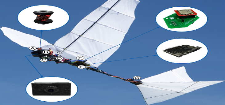
Aerodynamic surfaces (wings and tail) are made of an ultra lightweight ripstop nylon fabric adhered to an optimized carbon fiber structure made of tubes and rods. This carbon fiber structure was designed as a tradeoff between the aerodynamic, elastic, and inertial properties of the wing. As a result, the wing is shaped for optimal low speed flapping flight aerodynamics, and capable of gliding with a low descent rate, which makes this ornithopter suitable for safe landing even in emergency cases, as opposed to multirotors. Wing fabric and structure achieve 82 g for a total surface of 0.44 m2. Special emphasis was put into weight optimization over the wings. Lighter wings imply lower inertia forces during flapping, which become relevant at high speed flapping. Reducing wing inertia also reduces mechanical stresses over the flapping mechanism, and reduces the power demanded by the driving motor. Lower weight also gives more room available for additional payload.
The tail consists of a triangular horizontal stabilizer of 0.1 m2 plus a triangular rudder of half the size, providing longitudinal and directional stability and attitude control. Both surfaces are actuated with two concatenated servos, the first acting over the tail pitch, and the second, over the direction of the rudder. The tail pitch is used to control the aircraft nose pitch, and hence, the forward speed. The lack of roll actuations is mitigated by the roll stability that provides wing dihedral, and the directional stability and control provided by the rudder. The tail was trimmed for each weight distribution taking maximum glide ratio as criteria.
III-B Sensors
The sensors on board GRIFFIN Eye-Bird were selected considering their interest for addressing the flapping-wing robot perception challenges and the platform strict weight and size constraints. Data acquisition and collection was done with low-weight Khadas VIM3 board that equips a 6-core ARM CPU, an USB-3.0 interface, and a 16GB eMMC storage unit. The Khadas mounts Ubuntu 18.04 with ROS Melodic, and stores the collected data in the ROS bag format.
A significant effort was devoted to reduce the weight of the components on board the ornithopter. The main characteristics of onboard sensors are shown in Table II, including their weights after the adaptation to integrate them on the ornithopter. The total weight of all sensors, electronics, and batteries, including the required cables, was lower than 250 g, near to the maximum payload capacity for the ornithopter with the desired maneuverability.
| Sensor | Characteristics | Weight |
| DAVIS346 | DVS: 346x260 up to 12 MHz | |
| APS: 346x260@40 Hz | With custom | |
| FOV: 68 vert., 83 horiz. | case & lens: 57 g | |
| IMU: MPU 9250@1 kHz | ||
| VN-200 | IMU readings @80 Hz | |
| Gyroscope, accelerometer, | With adaptation | |
| and magnetometer available | board: 21 g | |
| GPS and barometer disabled | ||
| Leica MS50 TotalStation | Cent.-level tracking@10 Hz | Prism: 30 g |
| GRZ101 MiniPrism on the bird | ||
| OptiTrack | Cent.-level tracking@100 Hz | LEDs and |
| 5x850nm LEDs on the bird | cables: 5 g |
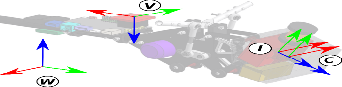
The main sensors mounted on GRIFFIN Eye-Bird are an iniVation DAVIS346 and a VectorNav VN-200. The DAVIS346 embeds three different sensors: (1) a 346x260 dynamic vision sensor (DVS) that outputs timestamped and polarized events at a maximum rate of 12 MHz and with a temporal resolution of 1 s; (2) a 346x260 active pixel sensor (APS) that is coincident with the DVS and outputs grayscale images at 40 Hz; and (3) a MPU 9250 IMU that delivers measurements at 1 kHz. To reduce its weight and fulfill the GRIFFIN Eye-Bird strict payload and weight distribution requirements, the lens and metallic case of the DAVIS346 have been removed and substituted by lighter components. Two different lenses, one for outdoors and one for indoors were used, the latter with an IR cut-off filter to cope with the OptiTrack IR emitters. Each had a weight of 5 g, a focal distance of 3.6 mm and a Field of View of 83∘ horizontal and 68∘ vertical. The case was replaced with a PLA (Polylactic Acid) 3D printed encapsulation. The total weight of the adapted DAVIS346 was 52 g, less than a third of its original weight, which was g (original lens included). The DAVIS346 was mounted at the head of the ornithopter with a pitch angle of 30∘, in a protective lightweight soft case –made by 3D printing using flexible TPU95 filament– that acts as a shock absorber in case of a frontal collision. To facilitate installation in the ornithopter head, the DAVIS346 was mounted upside down as seen in Figure 3, which shows the reference frames of each sensor. The VectorNav VN-200 includes a high-end IMU. It provides several times smaller noise density and in-run bias stability than the IMU embedded in the DAVIS346. It was installed as close as possible to the ornithopter center of gravity. The measurements from the VN-200 are accessed trough UART and published in ROS at 80 Hz using a custom package111https://github.com/grvcPerception/vn_ros_integration. The VectorNav can also mount a GPS, but was not installed due to the flight and maneuverability weight constraints. Instead, the position ground truth was obtained with a motion capture system (indoor scenarios) and a Leica Nova MS50 TotalStation laser tracker (outdoor scenarios), which provide significantly lower localization errors than GPS.
The MS50 TotalStation is able to follow a moving reflective target and provide precise range and bearing measurements of it, which can be translated to 3D cartesian coordinates. The mounted target is a GRZ101 360∘ MiniPrism, which was installed at the head of the ornithopter. To prevent occlusions, the TotalStation was placed at an obstacle-free location and as far as possible from the flight area to increase the TotalStation Field of View. Further, to prevent occlusions caused by the ornithopter body, the flights were arranged such that the prism faced the TotalStation during the trajectory. The strong ornithopter motions while flapping could occasionally cause temporal tracking failures that only affected to a fraction of the recorded data, enabling a reliable ground truth position reconstruction in outdoor flights. For indoor flights, an OptiTrack motion capture system with 28 cameras was used to provide millimeter accuracy ground truth position and orientation at a rate of 100 Hz. The ornithopter was tracked using five infrared (850 nm) LEDs installed at its main frame. The OptiTrack designated body frame was located at the position of the TotalStation prism.
IV Data Format and Calibration
All sensor measurements were recorded as ROS bag files using timestamped messages. The format of each sensor measurement is defined by the standard ROS message library. Besides, the events from the DAVIS346 DVS use the format defined in [25], in which each event is represented as , where is the time the event was triggered, are the event pixel coordinates, and is the event polarity either positive or negative. The images from the DAVIS346 APS include the pixel raw data, image resolution, and encoding. Further, the measurements from the VectorNav and DAVIS346 IMUs include referenced orientation, angular velocity, and linear acceleration. The measurements from the TotalStation and the Optitrack are formatted as timestamped poses (without orientation in the case of the TotalStation). Each measurement is referenced w.r.t. its sensor frame, see Figure 3. The world reference frame is taken as the frames of the TotalStation and the OptiTrack.
A calibration dataset was obtained before each set of flights. The raw dataset is provided so users can calibrate with their tool of preference. Each dataset includes images from the DAVIS346 APS, events from the DAVIS346 DVS, and measurements from the DAVIS346 IMU and the VectorNav. Additionally, a calibration file obtained with the Kalibr toolbox [26] is provided for each calibration dataset. The camera intrinsic calibration is recomputed at each calibration experiment. The extrinsic camera-IMU calibration of both IMUs is fixed as the most consistent calibration obtained by Kalibr through all the datasets, since it is less likely to change between flights and more affected by noise in the calibration data. Also, a 2-hours dataset of the IMUs measurements with the bird still is provided so users can obtain IMUs characterizations, e.g., using the Allan variance method222https://github.com/rpng/kalibr_allan. The calibrations were further validated by using them to execute a VIO (Visual-Inertial Odometry) algorithm in all the conducted flights, see Section V.
V The GRIFFIN Datasets
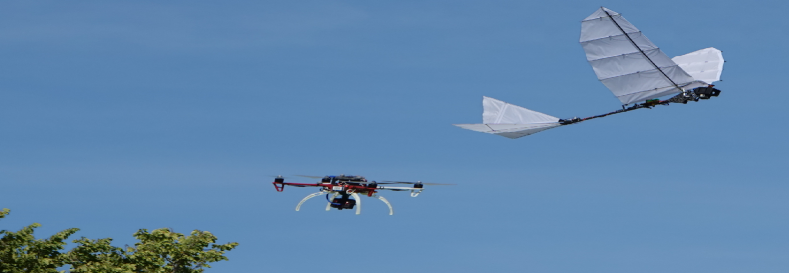
First, to better understand the effect of wing flapping on the onboard sensors, we performed a set of flights where the trajectories executed by the ornithopter were imitated by a multirotor UAV. The flights were repeated until the multi-rotor trajectories were similar to those performed by the ornithopter. The multirotor platform was a DJI FlameWheel F450 frame with a PixRacer autopilot equipped with a DAVIS346 (mounted with a 30o pitch rotation) and a Khadas VIM3 board for data logging using ROS, see Figure 4.
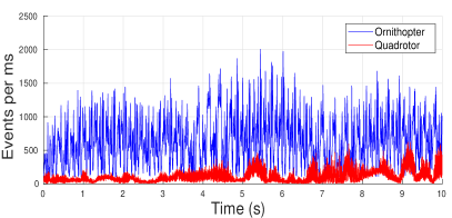
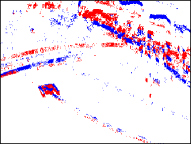
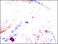
As expected, the experimental results show that the ornithopter suffers from significantly stronger vibrations than the multirotor. On average the DAVIS346 IMU registered 3 times greater accelerations in Eye-Bird than in the multirotor. These vibrations had direct impact on event generation: 6 times more events were triggered in Eye-Bird than in the multirotor. Figure 5-a,b shows the event images accumulated at 40 Hz gathered in both platforms when pointing to a similar part of the scenario. The ornithopter flight generated a significantly greater number of events than the multirotor. Although this effect depends on the scenario and type of flight, these differences were consistently observed in all the flights performed. As an example, Figure 5-c shows the number of events accumulated every millisecond while both platforms described a similar trajectory, confirming the intuition. Additionally, the abrupt changes in the ornithopter pitch angle during flapping often resulted in underexposed and overexposed visual images in outdoor scenarios, which imposes additional lighting robustness requirements to vision-based techniques suitable for ornithopters.
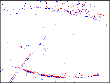
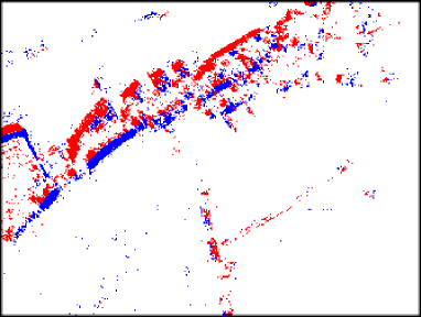
a) b)
c)
The dataset collection consisted on recording data from onboard and external sensors during the ornithopter flight. The measurements from the onboard sensors were recorded in the Khadas VIM3, while those from the TotalStation and OptiTrack were recorded in an external computer. The clocks in the Khadas VIM3 and in the external computer were synchronized using Network Time Protocol (NTP) [27].
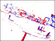
a) b) c) d)
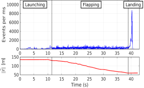
Data recording (of onboard and external sensors) was initialized before each flight. Just before being launched, the ornithopter was oriented such that the DAVIS346 pointed towards a referenced calibration grid in order to add visual reference and features. Next, the ornithopter was smoothly launched towards the flight area. Once in the air, the ornithopter was guided towards the landing area while performing different types of trajectories. Figure 6-top shows the number of events generated per millisecond during one of the dataset flights (Hills Base 3). The three flight stages –launching, flapping, and landing– can be inferred from the graph, since the event generation is affected by different dynamics. Figure 6-bottom shows , the module in world coordinates (W) of the position vector of the TotalStation prism throughout that flight. Temporal synchronization is noticed by comparing both graphs (e.g., the maximum number of events per millisecond matches the ornithopter landing). The ornithopter flights had different durations depending on the maneuvers performed and the type of dataset. Three types of datasets were recorded:
| Scenario | Dataset | (s) | (m) | (m/s) | (rad/s) | Max EPms (events/ms) | (m) | Ground Truth | Annotation |
| Testbed | Base1 | 27.99 | 96.12 | 3.16 | 0.29 | 3575 | 0.68 | OptiTrack | No |
| Base2 | 18.99 | 76.26 | 3.91 | 0.28 | 8171 | 0.59 | OptiTrack | No | |
| Base3 | 16.99 | 57.61 | 3.14 | 0.25 | 4094 | 1.03 | OptiTrack | No | |
| ArUco1 | 20.98 | 61.37 | 2.81 | 0.21 | 4295 | 0.41 | OptiTrack | No | |
| ArUco2 | 24.99 | 94.10 | 3.42 | 0.27 | 5073 | 0.55 | OptiTrack | No | |
| ArUco3 | 26.98 | 108.38 | 3.86 | 0.29 | 8726 | 0.46 | OptiTrack | No | |
| ArUco4 | 4.80 | 12.17 | 2.57 | 0.14 | 8631 | 0.06 | OptiTrack | No | |
| ArUco5 | 3.97 | 11.08 | 2.83 | 0.13 | 8616 | 0.13 | OptiTrack | No | |
| ArUco6 | 3.98 | 11.98 | 2.99 | 0.12 | 8667 | 0.21 | OptiTrack | No | |
| Hills | Base1 | 39.21 | 107.76 | 2.77 | – | 8704 | 1.20 | TotalStation | No |
| Base2 | 39.90 | 110.21 | 2.80 | – | 8784 | 2.48 | TotalStation | No | |
| Base3 | 42.91 | 98.75 | 2.52 | – | 8772 | 2.46 | TotalStation | No | |
| ArUco1 | 31.80 | 97.95 | 2.97 | – | 8840 | 2.14 | TotalStation | No | |
| ArUco2 | 27.21 | 114.93 | 4.31 | – | 6615 | 6.46 | TotalStation | No | |
| Soccer | Base1 | 24.89 | 54.65 | 2.22 | – | 8610 | 0.83 | TotalStation | No |
| Base2 | 20.01 | 43.41 | 2.16 | – | 8549 | 1.63 | TotalStation | No | |
| Base3 | 27.90 | 54.42 | 1.92 | – | 7166 | 1.91 | TotalStation | No | |
| ArUco1 | 15.31 | 51.49 | 3.47 | – | 7534 | 1.01 | TotalStation | No | |
| ArUco2 | 53.02 | 19.50 | 2.79 | – | 8757 | 1.12 | TotalStation | No | |
| People1 | 79.98 | – | – | – | 8737 | – | None | Yes | |
| People2 | 88.04 | – | – | – | 8729 | – | None | Yes |
-
•
In Base datasets the ornithopter described agile trajectories until it reached a safety altitude for landing. There were no artificial landmarks in the scenario and the maneuver varied depending on the wind conditions.
-
•
In ArUco datasets the ornithopter described smooth trajectories trying to flight over ArUco markers placed on the ground used to add ground truth references and features in the scene.
-
•
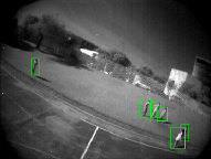
In People datasets the ornithopter flies over people and objects with the aim of providing samples for object detectors. To cover larger areas, the ornithopter described longer trajectories without altitude limitation, and hence, these datasets were recorded without measurements from the TotalStation.
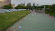
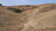
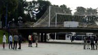
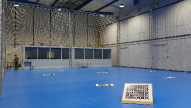
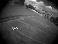
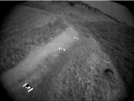
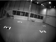
The datasets were recorded in two outdoor and one indoor environments, see Figure 7. The Soccer outdoor scenario is a small soccer field surrounded by obstacles with different heights such as threes, benches, and fences. Its total area is m. The ornithopter was launched from a small bridge structure in front the yard, while the TotalStation was located at an elevated spot located at m from the launching point. The Hills outdoor scenario is a large obstacle-free irregular area with hills and slopes. It is a large scenario ( m), which enables longer flights without obstacles or constrained flight space. The distance between the TotalStation and the launching spot was m. The Testbed indoor scenario was a m room designed for testing ornithopters and equipped with an OptiTrack motion capture system. In the simplest indoor trajectories Eye-Bird was controlled autonomously with a simplified method inspired in [17], which used the OptiTrack measurements. These datasets can be of interest for developing onboard perception techniques for closing the low-level control loop. In the outdoor and the most complex indoor flights Eye-Bird was controlled manually by an expert pilot to better compensate for the wind disturbances and perform richer trajectories that exploit the ornithopter maneuverability and also evidence the challenges of flapping for perception.
Table III lists the 21 provided datasets, 9 of them conducted in the Testbed scenario, 7 in the Soccer scenario, and 5 in Hills. A total of 10 ArUco and 9 Base datasets are provided due to their interest for perception techniques in partially structured (ArUco) and fully unstructured (Base) environments. People datasets were conducted in the Soccer scenario. In these datasets annotated bounding boxes are provided to facilitate training for people detection algorithms. For safety, we did not record People datasets in the Testbed. Also, in the Hills scenario the robot flew at high altitudes, which hampered the correct identification of objects. Table III also shows the maximum number of events generated per millisecond in each flight. The maximum event throughput of DAVIS346 is 12 Million Events Per Second, i.e. 12,000 events per millisecond. Hence, the number of events generated per millisecond in all flights were lower than the DAVIS346 throughput, i.e. no event was discarded in any dataset. For instance, Figure 6-top shows the events triggered during the Hills Base 3 flight. The number of generated events is always lower than the maximum event throughput of DAVIS346 even when the ornithopter impacts on the ground. In all conducted flights the maximum event rate takes place when the ornithopter impacts on the ground, and this value is at least 5 times bigger than the mean event rate during the rest of the flight.
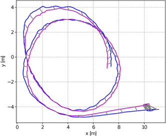
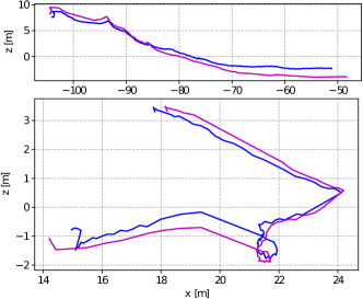
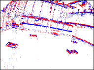
To complement the dataset, a VIO algorithm was evaluated in all the flights and compared to the provided ground truth. This is valuable for confirming the usability and validity of the provided dataset, assessing the quality of the given calibration and ground truth, and providing a baseline result for comparison with other VIO methods. The chosen method was ROVIO [28], a robust and well-known method capable of providing estimates of the robot trajectory without intensive parameter tuning. Figure 8 shows the ornithopter trajectory estimated with ROVIO versus the ground truth in one flight in each scenario. The absolute translation RMSE (root mean square error) of the VIO trajectory at each flight w.r.t. the position ground truth is provided in Table III. The execution of ROVIO was cut before the landing, where no visual features are present. The absolute error provided by ROVIO in dataset Hills ArUco2 is caused by drift and confirms the limitation of existing techniques with flapping-wing flights.
VI Conclusions and Future Work
The development of perception techniques for flapping-wing robots faces a number of issues. First, the high mechanical vibrations and sudden motion of these platforms originates motion blur and drastic changes in lighting conditions. Besides, the lack of available ornithopters with suitable payload capacity and the difficulties in the development of these platforms set an additional entry barrier.
This paper presented a perception dataset for bird-scale flapping-wing robots, i.e. ornithopters, recorded in two outdoor and one indoor scenarios. It includes measurements from an event camera, a conventional camera, and two IMUs, as well as ground truth data from laser tracker (in outdoor scenarios) and motion capture system (in indoor scenarios). The provided data include: datasets with agile trajectories that exhibit the ornithopter maneuverability; datasets with smooth trajectories and ArUco markers in the scenario; and datasets for developing and evaluating event-based and visual-based object detection techniques.
The development of perception techniques based on the aforementioned sensors for online execution on board the ornithopter is object of current research. The motion blur and sudden lighting changes observed in the presented datasets recommend the use of event cameras. The vast amount of information captured by the event camera during the ornithopter flight together with the strong payload limitations of these platforms require a significant effort for developing event-based vision methods that can be online and onboard executed. This work intends to set the baseline for future research and contribute to pave the way to develop perception systems that endow the necessary capabilities for ornithopter robots to perceive and interact with the environment.
Acknowledgment
The authors would like to thank the support of Rafael Salmoral as multirotor operator, Martín Pérez at the preparation of the flights, and Miguel Pérez for data annotation.
References
- [1] G. A. Folkertsma, W. Straatman, N. Nijenhuis, C. H. Venner, and S. Stramigioli, “Robird: a robotic bird of prey,” IEEE Robotics & Automation Magazine, vol. 24, no. 3, pp. 22–29, 2017.
- [2] Smartbird–bird flight deciphered. [Online]. Available: https://www.festo.com/group/en/cms/10238.htm
- [3] S. W. Ryu, J. G. Lee, and H. J. Kim, “Design, fabrication, and analysis of flapping and folding wing mechanism for a robotic bird,” Journal of Bionic Engineering, vol. 17, pp. 229–240, 2020.
- [4] E. Farrell Helbling and R. J. Wood, “A review of propulsion, power, and control architectures for insect-scale flapping-wing vehicles,” Applied Mechanics Reviews, vol. 70, no. 1, pp. 1–9, 2018.
- [5] A. G. Eguíluz, J. P. Rodríguez-Gómez, J. L. Paneque, P. Grau, J. R. M. de Dios, and A. Ollero, “Towards flapping wing robot visual perception: Opportunities and challenges,” in 2019 Workshop on Research, Education and Development of Unmanned Aerial Systems (RED UAS), 2019, pp. 335–343.
- [6] M. Fonder and M. Van Droogenbroeck, “Mid-air: A multi-modal dataset for extremely low altitude drone flights,” in IEEE Conf. on Computer Vision and Pattern Recognition Workshops, 2019, pp. 553–562.
- [7] I. Bozcan and E. Kayacan, “Au-air: A multi-modal unmanned aerial vehicle dataset for low altitude traffic surveillance,” in IEEE Intl. Conf. on Robotics and Automation (ICRA), pp. 8504––8510.
- [8] F. Maffra, L. Teixeira, Z. Chen, and M. Chli, “Real-time wide-baseline place recognition using depth completion,” IEEE Robotics and Automation Letters, vol. 4, no. 2, pp. 1525–1532, April 2019.
- [9] M. Burri, J. Nikolic, P. Gohl, T. Schneider, J. Rehder, S. Omari, M. W. Achtelik, and R. Siegwart, “The euroc micro aerial vehicle datasets,” The International Journal of Robotics Research, vol. 35, no. 10, pp. 1157–1163, 2016.
- [10] A. L. Majdik, C. Till, and D. Scaramuzza, “The Zurich urban micro aerial vehicle dataset,” The International Journal of Robotics Research, vol. 36, no. 3, pp. 269–273, 2017.
- [11] A. Antonini, W. Guerra, V. Murali, T. Sayre-McCord, and S. Karaman, “The blackbird dataset: A large-scale dataset for uav perception in aggressive flight,” in International Symposium on Experimental Robotics. Springer, 2018, pp. 130–139.
- [12] K. Sun, K. Mohta, B. Pfrommer, M. Watterson, S. Liu, Y. Mulgaonkar, C. J. Taylor, and V. Kumar, “Robust stereo visual inertial odometry for fast autonomous flight,” IEEE Robotics and Automation Letters, vol. 3, no. 2, pp. 965–972, 2018.
- [13] A. Z. Zhu, D. Thakur, T. Özaslan, B. Pfrommer, V. Kumar, and K. Daniilidis, “The multivehicle stereo event camera dataset: An event camera dataset for 3d perception,” IEEE Robotics and Automation Letters, vol. 3, no. 3, pp. 2032–2039, 2018.
- [14] J. Delmerico, T. Cieslewski, H. Rebecq, M. Faessler, and D. Scaramuzza, “Are we ready for autonomous drone racing? the UZH-FPV drone racing dataset,” in IEEE Intl. Conf. on Robotics and Automation (ICRA), 2019, pp. 6713––6719.
- [15] J. P. Rodríguez-Gómez, A. Gómez Eguíluz, J. R. Martinez De-Dios, and A. Ollero, “ROSS-LAN: RObotic Sensing Simulation scheme for bioinspired robotic bird LANding,” in Iberian Robotics conference. Springer, 2019, pp. 48–59.
- [16] E. Pan, X. Liang, and W. Xu, “Development of vision stabilizing system for a large-scale flapping-wing robotic bird,” IEEE Sensors Journal, pp. 8017––8028, July 2020.
- [17] F. Maldonado, J. Acosta, J. Tormo-Barbero, P. Grau, M. Guzmán, and A. Ollero, “Adaptive nonlinear control for perching of a bioinspired ornithopter,” in IEEE/RSJ Intl. Conf. on Intelligent Robots and Systems (IROS), 2020, pp. 1385–1390.
- [18] G. Gallego, T. Delbruck, G. M. Orchard, C. Bartolozzi, B. Taba, A. Censi, S. Leutenegger, A. Davison, J. Conradt, K. Daniilidis, and D. Scaramuzza, “Event-based vision: A survey,” IEEE Transactions on Pattern Analysis and Machine Intelligence, pp. 1–1, 2020.
- [19] A. Gómez Eguíluz, J. P. Rodríguez-Gómez, J. R. Martínez-de Dios, and A. Ollero, “Asynchronous event-based line tracking for time-to-contact manuevers in UAS,” in IEEE/RSJ Intl. Conf. on Intelligent Robots and Systems (IROS), 2020, pp. 5978–5985.
- [20] A. Mitrokhin, C. Ye, C. Fermüller, Y. Aloimonos, and T. Delbruck, “Ev-imo: Motion segmentation dataset and learning pipeline for event cameras,” in 2019 IEEE/RSJ International Conference on Intelligent Robots and Systems (IROS), 2019, pp. 6105–6112.
- [21] J. P. Rodríguez-Gómez, A. Gómez Eguíluz, J. R. Martínez-de Dios, and A. Ollero, “Asynchronous event-based clustering and tracking for intrusion monitoring in UAS,” in IEEE Intl. Conf. on Robotics and Automation (ICRA), pp. 8518––8524.
- [22] A. R. Vidal, H. Rebecq, T. Horstschaefer, and D. Scaramuzza, “Ultimate slam? combining events, images, and imu for robust visual slam in hdr and high-speed scenarios,” IEEE Robotics and Automation Letters, vol. 3, no. 2, pp. 994–1001, April 2018.
- [23] R. Tapia, A. Gómez Eguíluz, J. Martınez-de Dios, and A. Ollero, “ASAP: Adaptive scheme for asynchronous processing of event-based vision algorithms,” in IEEE ICRA Workshop on Unconventional Sensors in Robotics, 2020, pp. 1–3.
- [24] A. Mitrokhin, C. Fermüller, C. Parameshwara, and Y. Aloimonos, “Event-based moving object detection and tracking,” in IEEE/RSJ Intl. Conf. on Intelligent Robots and Systems (IROS), 2018, pp. 1–9.
- [25] E. Mueggler, H. Rebecq, G. Gallego, T. Delbruck, and D. Scaramuzza, “The event-camera dataset and simulator: Event-based data for pose estimation, visual odometry, and SLAM,” The International Journal of Robotics Research, vol. 36, no. 2, pp. 142–149, 2017.
- [26] J. Rehder, J. Nikolic, T. Schneider, T. Hinzmann, and R. Siegwart, “Extending kalibr: Calibrating the extrinsics of multiple IMUs and of individual axes,” in IEEE Intl. Conf. on Robotics and Automation (ICRA), 2016, pp. 4304–4311.
- [27] D. L. Mills, “Internet time synchronization: the network time protocol,” IEEE Transactions on communications, vol. 39, no. 10, pp. 1482–1493, 1991.
- [28] M. Bloesch, M. Burri, S. Omari, M. Hutter, and R. Siegwart, “Iterated extended kalman filter based visual-inertial odometry using direct photometric feedback,” The International Journal of Robotics Research, vol. 36, no. 10, pp. 1053–1072, 2017.