Long-range spin-wave propagation in transversely magnetized nano-scaled conduits
Abstract
Magnonics attracts increasing attention in the view of novel low-energy computation technologies based on spin waves. Recently, spin-wave propagation in longitudinally magnetized nano-scaled spin-wave conduits was demonstrated, proving the fundamental feasibility of magnonics at the sub- scale. Transversely magnetized nano-conduits, which are of great interest in this regard as they offer a large group velocity and a potentially chirality-based protected transport of energy, have not yet been investigated due to their complex internal magnetic field distribution. Here, we present a study of propagating spin waves in a transversely magnetized nanoscopic yttrium iron garnet conduit of width. Space and time-resolved micro-focused Brillouin-light-scattering spectroscopy is employed to measure the spin-wave group velocity and decay length. A long-range spin-wave propagation is observed with a decay length of up to and a large spin-wave lifetime of up to . The results are supported with micro-magnetic simulations, revealing a single-mode dispersion relation in contrast to the common formation of localized edge modes for microscopic systems. Furthermore, a frequency non-reciprocity for counter-propagating spin waves is observed in the simulations and the experiment, caused by the trapezoidal cross-section of the structure. The revealed long-distance spin-wave propagation on the nanoscale is particularly interesting for an application in spin-wave devices, allowing for long-distance transport of information in magnonic circuits, as well as novel low-energy device architectures.
Magnonics, the research field of spin-wave based data transport and information processing, aims to complement CMOS-based computation technology by replacing the charge-based binary logic with a wave-based logic Serga, Chumak, and Hillebrands (2010); Khitun, Bao, and Wang (2010); Kruglyak, Demokritov, and Grundler (2010); Chumak et al. (2015); Mahmoud et al. (2020a). Utilizing spin waves as information carriers provides a variety of advantages such as a high energy efficiency due to the absence of ohmic losses Kajiwara et al. (2010); Yu et al. (2014); Dubs et al. (2020) and additional degrees of freedom since frequency and phase of a spin wave are readily accessible Schneider et al. (2008a). Moreover, spin-wave systems inherit a multitude of nonlinear mechanisms Krivosik and Patton (2010); Demidov et al. (2009a); Chumak, Serga, and Hillebrands (2014); Sadovnikov et al. (2016) while being scaleable to the nanoscale Wang et al. (2019); Heinz et al. (2020), allowing for a novel device architecture Brächer and Pirro (2018); Papp et al. (2017) and simultaneously reducing the device feature size to sizes comparable or even smaller than their CMOS-based equivalent Wang et al. (2020a). A large number of spin-wave based devices and logic elements have been realized in the recent years such as transistors Chumak et al. (2015); Wu et al. (2018); Cramer et al. (2018), majority gates Klingler et al. (2014); Fischer et al. (2017); Mahmoud et al. (2020b), directional coupler Wang et al. (2018), half-adder Wang et al. (2020a) or de-/multipexer Heussner et al. (2020), with many more theoretical concepts proposed Wang et al. (2020b); Wang, Chumak, and Pirro (2020). While being well investigated on the macro- and microscale, the study of nano-sized magnonic elements has just scratched the surface due to the limited spin-wave propagation distance on this scale and the difficulties accompanying the fabrication of nano-sized magnetic elements. Only recent progress pushed the go-to material of magnonics, yttrium iron garnet (YIG), to the nanoscaleWang et al. (2019) revealing a reasonably large exponential decay length of in longitudinally magnetized YIG nano-conduits Heinz et al. (2020). Although a further perfection of material growth or the usage of new materials with improved characteristics might allow for an increase of the spin-wave propagation length, it is already apparent that the dominating loss channels in such systems are not intrinsic processes Gurevich and Melkov (1996), but extrinsic scattering processes mediated by lattice defects, surface roughness or magnetic inhomogeneities Heinz et al. (2020). Thus, novel approaches to avoid and eliminate these scattering processes are of great interest. Among them, the transport of information using topological protected (e.g. based on the Dzyaloshinskii-Moriya interaction Zhang et al. (2013); Shindou et al. (2013); Iacocca and Heinonen (2017); Wang, Zhang, and Wang (2018); Yamamoto et al. (2019)) or backscattering immune (caused by the intrinsic spin-wave mode chirality) spin-wave states is investigated. As it has been shown recently, magnetostatic surface waves (MSSWPrabhakar and Stancil (2009)) feature such a backscattering immunity to surface defects due to the presence of energy gaps in the volume mode spectrum, rendering them insensitive to significant structural defects Mohseni et al. (2019, 2020). In addition, in nanometer thick films, MSSWs are known to provide a much larger group velocity in comparison to other spin-wave modesGurevich and Melkov (1996); Bhaskar et al. (2020), which renders these waves an interesting subject of investigation regarding a long-distance data transport in magnonic circuits. However, MSSW require a transverse magnetization state leading to a strongly non-uniform internal magnetic field distribution in laterally confined nanostructures, which causes the formation of localized edge-mode states and separated volume statesBayer et al. (2004); Gubbiotti et al. (2004); Pirro et al. (2014). For nano-scaled conduits this field non-uniformity is even more pronounced and, in addition, a strong quantization is present, resulting in a complex interplay. Therefore, the mode structure in transversely magnetized nano-scaled systems is still an open question.
Here, we report on the investigation of propagating spin waves in a transversely-magnetized nano-sized YIG conduit of width. We show that spin waves can propagate in such a waveguide in spite of the strong non-uniformity of the internal magnetic field, observing a large spin-wave decay length up to . In addition, a non-reciprocity for counter-propagating spin waves is observed, which opens up the path for new device architectures. The experimental findings are supported with micro-magnetic simulations, revealing a single-mode dispersion relationship in contrast to the common formation of edge modes for microscopic systems .
In this study, a thin lanthanum-doped \hkl(111) YIG film of thickness is used which is grown by liquid phase epitaxy Dubs et al. (2017, 2020) on top of a thick \hkl(111) gadolinium gallium garnet substrate. A characterization of the plain film by means of vector network analyzer ferromagnetic resonance spectroscopy Kalarickal et al. (2006); Maksymov and Kostylev (2015) and micro-focused Brillouin-light-scattering (BLS) spectroscopy Sebastian et al. (2015) revealed the following material parameters: saturation magnetization , Gilbert damping parameter inhomogeneous linewidth broadening and exchange constant . These parameters are within the typical range for high-quality thin YIG films Dubs et al. (2017, 2020). Nanoscopic waveguides were fabricated using a hard mask ion beam milling procedure Heinz et al. (2020) resulting in conduits with a trapezoidal cross-section. The bottom of the structure is wide while the top width is as narrow as , which was determined by scanning electron microscopy, see Fig. 1.
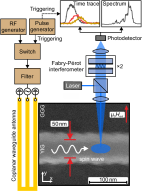
Afterwards, a gold coplanar waveguide (CPW) antenna was added on top of the waveguide with a center-to-center distance of ground and signal line of , a line width of and a thickness of . In the experiment, a large bias magnetic field of is applied in-plane along the short axis of the structure to ensure a transversely magnetized state. Radio-frequency (RF) continuous-wave (cw) currents or pulses with length and repetition time are generated and fed into the CPW antenna using an RF generator in combination with a fast switch and filter elements. Subsequently, propagating spin-wave packets are excited in the YIG waveguide and are detected using micro-focused BLS spectroscopy. A single-frequency laser operating at is used which is focused through the substrate of the sample on the structure using a compensating microscope objective (magnification , numerical aperture ). In-plane spin-wave wavevectors up to can be detected. The laser spot diameter is approximately and the effective laser power on the sample is .
To support the findings, micro-magnetic simulations are performed using the MuMax open source framework Vansteenkiste et al. (2014). The trapezoidal waveguide is modeled with the following dimensions: length, and bottom and top width respectively and thickness. The cell size is , thus introducing thickness layers with discrete varying width. The material parameters of the plain film are used in the simulations, since it has been shown that the structuring process only has a moderate influence on the structures properties Heinz et al. (2020). An external magnetic field of is applied in-plane along the short axis of the structure and a ground state is prepared by relaxing a random magnetization distribution. Afterwards, a driving magnetic field is applied with a spacial field distribution corresponding to the CPW antennas magnetic field to excite spin-wave packets. Time- and spacial Fourier transformations allow to extract the dispersion relationship and connected parameters.
First, the spin-wave spectra are investigated for the case of a cw microwave excitation. The results are presented in Fig. 2 for different distances to the CPW antenna, (Fig. 2A) and (Fig. 2B) respectively.
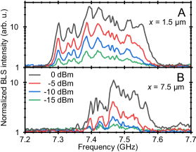
The applied microwave power is varied to reveal the possible occurrence of nonlinear scattering processes which would act as additional loss channels and influence a measurement of the decay length of the system. As shown in Fig. 2A, the shape of the spectrum is conserved for different applied powers, thus indicating that no strong nonlinear effects arise in the selected microwave power range. The observed spectrum has a spectral width of and shows a complex behaviour, which might be attributed to microwave transmission characteristics of the used CPW antenna. Comparing the spectral distribution close to the antenna to the distribution after several micrometer of propagation (Fig. 2B) reveals that the low-frequency part of the spectrum is strongly attenuated. These states are likely close to the ferromagnetic resonance of the structure and thus, as it is shown in the following, exhibit only a small group velocity.
To support the findings, micro-magnetic simulations are conducted using a sinc-function pulse to realize a broadband excitation of the whole dispersion relation. In Fig. 3A the resulting excited spectrum is shown for the experimentally accessible wavevector range.
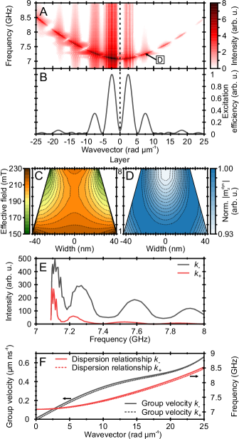
A clear single mode state is observed following a monotonous function. However, the absolute frequency is shifted by approximately with respect to the experimental results of Fig. 2, which indicates that the magnetic parameters are slightly alternated by the structuring process Heinz et al. (2020). In addition, a small variation of the magnetic width of the structure can also significantly impact the spin-wave frequency on the present scale. The various small gaps in the dispersion relationship are caused by the wavevector selective excitation efficiency of the CPW antenna, as shown in Fig. 3B. Here, the efficiency is approximated by the spacial Fourier transformation of the in-plane field distribution, for a detailed discussion see Demidov et al. (2009b). The simulated internal field distribution of the ground state is shown in Fig. 3C. As expected, large demagnetizing fields arise leading to a strongly non-uniform internal field distribution along the external magnetic field direction. Similar to micron-sized conduits distinct regions of a significantly reduced effective magnetic field are formed at the edges of the structure. However, since the structure is too small to allow for a homogeneous field region in the center, a single mode behaviour is observed in contrast to the typically observed appearance of localized edge mode states. This is validated by the mode profile (normalized absolute value of the dynamic out-of-plane magnetization component ) shown in Fig. 3D for a frequency of and , which extents fully into the edge regime of the structure.
Extracting the respective spectral distribution, see Fig. 3E, shows an intensity difference for counter-propagating waves ( and ), which is caused by a non-reciprocal excitation efficiency of MSSW when using a microwave antennaSchneider et al. (2008a); Demidov et al. (2009b). Moreover, comparing the spectra to Fig. 2 indicates that the experiment is limited to the first two excitation efficiency maxima of the CPW antenna. Excitation maxima of higher order are likely not observed due to the limited sensitivity of the used BLS setup, especially due to the small amount of probed material and the background of thermal spin waves leading to an increased noise level in the experiment.
In Fig. 3F the dispersion relationship, derived from a 6th-order polynomial approximation of Fig. 3A, and the a group velocity, extracted as the derivative of the dispersion relationship, are shown. Similar to microscopic systems, the transversely magnetized state offers a high and much larger group velocity than the waves of the corresponding longitudinal magnetized state possess Heinz et al. (2020).
In the following, the group velocity and the decay length are determined experimentally by a direct measurement of propagating spin-wave packets to further characterize the system and investigate whether a long range spin-wave propagation can be realized in such nano-scaled systems. Thus, a pulsed excitation with pulse length and repetition time is used, choosing an applied microwave power of to ensure an operation within the linear regime. In Fig. 4A time-resolved BLS measurements of the excited spin-wave packets are shown for different positions along the conduit.
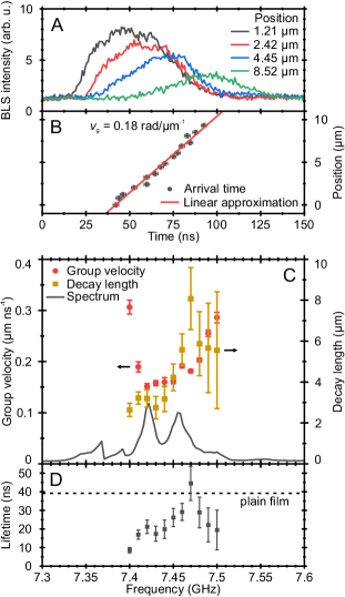
The respective center-of-mass arrival time of the pulse is determined by subtracting the thermal noise and calculating the weighted average of the packet. A linear approximation of the packet arrival time, as shown in Fig. 4B, yields the group velocity . Additionally, the decay length can be extracted from the integrated pulse intensity of each position by approximating the decay as follows:
| (1) |
Here, denotes the initial intensity, the offset intensity, the position, and the decay length. Extracted accordingly to this principle, the resulting group velocities and decay lengths are presented in Fig. 4C. The velocity lies within the expected range predicted by the simulations when compared for wavevectors up to , see Fig. 3F, and follows the rising trend to higher frequencies. However, an unexpected large velocity is observed for the smallest investigated frequency not covered by the prediction of the simulations. In contrast, the decay length follows a steep increase up to a maximum of , slightly dropping off for higher frequencies. For comparison, the corresponding cw excitation spectrum is displayed in light gray, which is, however, slightly shifted to smaller frequencies due to a small magnetic field difference of . Taking this shift into account, the second spectral peak matches the frequency of the maximum decay length. We would like to point out, that the observed decay length of is significantly larger in comparison to reported values in the longitudinal magnetization configuration of Heinz et al. (2020). This potentially enables complex nano-sized integrated spin-wave circuits consisting of multiple elements without any means of intermediate amplification, severely lowering the energy consumption of such circuits.
In the following, the lifetime of the propagating waves, shown in Fig. 4D, is derived from the experimental results using the expression
| (2) |
Here, a rather large lifetime of up to is found. Calculating the lifetime of the ferromagnetic resonance of the plain film as a comparisonPrabhakar and Stancil (2009), considering the decreased internal magnetic field of the transverse magnetization state, results in for only Gilbert type losses and taking the full linewidth into account. Here, two effects likely take place affecting the considerations: On the one hand, the structuring procedure influences the material parametersHeinz et al. (2020) and potentially reduces the lifetime compared to the plain film. On the other hand, the non-local inhomogeneous linewidth broadening extracted from the plain film overestimates the effective inhomogeneity on the length scale of the nanostructureHahn et al. (2014). Thus, a comparison to the full linewidth of the plain film can yield a lifetime smaller than the lifetime of the nanostructure. Nonetheless the measured lifetime exceeds other commonly used materials such as permalloyYamanoi et al. (2013) by far, even when comparing to microscopic or macroscopic systems.
Finally, we would like to discuss a peculiarity of the investigated system, observed in Fig. 3 F. The simulated dispersion relationship exhibits a small frequency non-reciprocity, which is caused by the trapezoidal cross-section of the structure and the associated internal field distribution (Fig. 3C). This introduces an additional spacial symmetry break, similar to the case of magnetic bilayers Grassi et al. (2020). In Fig. 5 two measured spectra for normal and inverted field polarity are shown, which equals a switch of the dispersion branch from to .
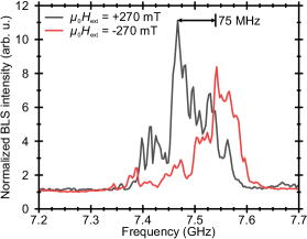
Indeed, a distinct non-reciprocity with a frequency shift of is found, which is substantially larger than the predicted shift of – for spin waves in the range of –, see Fig. 3F. It should be noted that, the observed frequency shift is likely influenced by the non-reciprocal excitation efficiency for both configurations, leading to different spin-wave densities, and thus to a different nonlinear frequency downshift potentially increasing the observed frequency gap. Nonetheless, such a pronounced non-reciprocity is of particular interest for an application in spin-wave devices since it allows for a novel device architecture, e.g. allows for the construction of a nano-sized spin-wave diode.
To conclude, we presented a study of propagating spin-wave packets in a transversely magnetized nano-scaled YIG conduit of width. Micro-magnetic simulations are performed to support the experimental findings, revealing a single-mode dispersion relationship in contrast to the common formation of localized edge modes for microscopic systems. It is shown that the observed mode is not localized within the central part of the structure. A large spin-wave group velocity is measured and a long-range spin-wave propagation is observed with a decay length of up to , which is multiple times larger than reported values for the corresponding longitudinal magnetized stateHeinz et al. (2020). In addition, a large spin-wave lifetime of up to is found. Furthermore, a frequency non-reciprocity for counter-propagating spin waves is observed and experimentally verified, which is caused by the trapezoidal cross-section of the structure and the associated internal field distribution. This non-reciprocity and the revealed long-distance spin-wave propagation on the nanoscale are particularly interesting for an application in spin-wave devices, allowing for long-distance transport of information in magnonic circuits, as well as novel low-energy device architectures potentially opening up the path to multi-element circuits without intermediate amplification.
This research has been funded by the European Research Council project ERC Starting Grant 678309 MagnonCircuits, by the Deutsche Forschungsgemeinschaft (DFG, German Research Foundation) - 271741898, by the Collaborative Research Center SFB/TRR 173-268565370 (Project B01), and by the Austrian Science Fund (FWF) through the project I 4696-N. B.H. acknowledges support from the Graduate School Material Science in Mainz (MAINZ). The authors thank Burkard Hillebrands for support and valuable discussions.
References
- Serga, Chumak, and Hillebrands (2010) A. A. Serga, A. V. Chumak, and B. Hillebrands, J. Phys. D: Appl. Phys 43, 264002 (2010).
- Khitun, Bao, and Wang (2010) A. Khitun, M. Bao, and K. L. Wang, J. Phys. D: Appl. Phys 43, 264005 (2010).
- Kruglyak, Demokritov, and Grundler (2010) V. V. Kruglyak, S. O. Demokritov, and D. Grundler, J. Phys. D: Appl. Phys 43, 260301 (2010).
- Chumak et al. (2015) A. V. Chumak, V. I. Vasyuchka, A. A. Serga, and B. Hillebrands, Nat. Phys. 11, 453 (2015).
- Mahmoud et al. (2020a) A. Mahmoud, F. Ciubotaru, F. Vanderveken, A. V. Chumak, S. Hamdioui, C. Adelmann, and S. Cotofana, J. Appl. Phys. 128, 161101 (2020a).
- Kajiwara et al. (2010) Y. Kajiwara, K. Harii, S. Takahashi, J. Ohe, K. Uchida, M. Mizuguchi, H. Umezawa, H. Kawai, K. Ando, K. Takanashi, S. Maekawa, and E. Saitoh, Nature 464, 262 (2010).
- Yu et al. (2014) H. Yu, O. d. Kelly, V. Cros, R. Bernard, P. Bortolotti, A. Anane, F. Brandl, R. Huber, I. Stasinopoulos, and D. Grundler, Sci. Rep. 4, 6848 (2014).
- Dubs et al. (2020) C. Dubs, O. Surzhenko, R. Thomas, J. Osten, T. Schneider, K. Lenz, J. Grenzer, R. Hübner, and E. Wendler, Phys. Rev. Mater. 4, 024416 (2020).
- Schneider et al. (2008a) T. Schneider, A. A. Serga, B. Leven, B. Hillebrands, R. L. Stamps, and M. P. Kostylev, Appl. Phys. Lett. 92, 022505 (2008a).
- Krivosik and Patton (2010) P. Krivosik and C. E. Patton, Phys. Rev. B 82, 184428 (2010).
- Demidov et al. (2009a) V. E. Demidov, J. Jersch, K. Rott, P. Krzysteczko, G. Reiss, and S. O. Demokritov, Phys. Rev. Lett. 102, 177207 (2009a).
- Chumak, Serga, and Hillebrands (2014) A. V. Chumak, A. A. Serga, and B. Hillebrands, Nat. Commun. 5, 4700 (2014).
- Sadovnikov et al. (2016) A. V. Sadovnikov, E. N. Beginin, M. A. Morozova, Y. P. Sharaevskii, S. V. Grishin, S. E. Sheshukova, and S. A. Nikitov, Appl. Phys. Lett. 109, 042407 (2016).
- Wang et al. (2019) Q. Wang, B. Heinz, R. Verba, M. Kewenig, P. Pirro, M. Schneider, T. Meyer, B. Lägel, C. Dubs, T. Brächer, and A. V. Chumak, Phys. Rev. Lett. 122, 247202 (2019).
- Heinz et al. (2020) B. Heinz, T. Brächer, M. Schneider, Q. Wang, B. Lägel, A. M. Friedel, D. Breitbach, S. Steinert, T. Meyer, M. Kewenig, C. Dubs, P. Pirro, and A. V. Chumak, Nano Lett. 20, 4220 (2020).
- Brächer and Pirro (2018) T. Brächer and P. Pirro, J. Appl. Phys. 124, 152119 (2018).
- Papp et al. (2017) Á. Papp, W. Porod, Á. I. Csurgay, and G. Csaba, Sci. Rep. 7, 9245 (2017).
- Wang et al. (2020a) Q. Wang, M. Kewenig, M. Schneider, R. Verba, F. Kohl, B. Heinz, M. Geilen, M. Mohseni, B. Lägel, F. Ciubotaru, and et al., Nat. Electron. 3, 765–774 (2020a).
- Wu et al. (2018) H. Wu, L. Huang, C. Fang, B. S. Yang, C. H. Wan, G. Q. Yu, J. F. Feng, H. X. Wei, and X. F. Han, Phys. Rev. Lett. 120, 097205 (2018).
- Cramer et al. (2018) J. Cramer, F. Fuhrmann, U. Ritzmann, V. Gall, T. Niizeki, R. Ramos, Z. Qiu, D. Hou, T. Kikkawa, J. Sinova, U. Nowak, E. Saitoh, and M. Kläui, Nat. Commun. 9, 1089 (2018).
- Klingler et al. (2014) S. Klingler, P. Pirro, T. Brächer, B. Leven, B. Hillebrands, and A. V. Chumak, Appl. Phys. Lett. 105, 152410 (2014).
- Fischer et al. (2017) T. Fischer, M. Kewenig, D. A. Bozhko, A. A. Serga, I. I. Syvorotka, F. Ciubotaru, C. Adelmann, B. Hillebrands, and A. V. Chumak, Appl. Phys. Lett. 110, 152401 (2017).
- Mahmoud et al. (2020b) A. Mahmoud, F. Vanderveken, C. Adelmann, F. Ciubotaru, S. Hamdioui, and S. Cotofana, AIP Adv. 10, 035119 (2020b).
- Wang et al. (2018) Q. Wang, P. Pirro, R. Verba, A. Slavin, B. Hillebrands, and A. V. Chumak, Sci. Adv. 4 (2018).
- Heussner et al. (2020) F. Heussner, G. Talmelli, M. Geilen, B. Heinz, T. Brächer, T. Meyer, F. Ciubotaru, C. Adelmann, K. Yamamoto, A. A. Serga, B. Hillebrands, and P. Pirro, Phys. Status Solidi Rapid Res. Lett. 14, 1900695 (2020).
- Wang et al. (2020b) Q. Wang, A. Hamadeh, R. Verba, V. Lomakin, M. Mohseni, B. Hillebrands, A. V. Chumak, and P. Pirro, npj Comput. Mater. 6, 192 (2020b).
- Wang, Chumak, and Pirro (2020) Q. Wang, A. V. Chumak, and P. Pirro, “Inverse-design magnonic devices,” (2020), arXiv:2012.04544 .
- Gurevich and Melkov (1996) A. G. Gurevich and G. A. Melkov, Magnetization oscillations and waves (CRC press, 1996).
- Zhang et al. (2013) L. Zhang, J. Ren, J.-S. Wang, and B. Li, Phys. Rev. B 87, 144101 (2013).
- Shindou et al. (2013) R. Shindou, J.-i. Ohe, R. Matsumoto, S. Murakami, and E. Saitoh, Phys. Rev. B 87, 174402 (2013).
- Iacocca and Heinonen (2017) E. Iacocca and O. Heinonen, Phys. Rev. Appl. 8, 034015 (2017).
- Wang, Zhang, and Wang (2018) X. S. Wang, H. W. Zhang, and X. R. Wang, Phys. Rev. Appl. 9, 024029 (2018).
- Yamamoto et al. (2019) K. Yamamoto, G. C. Thiang, P. Pirro, K.-W. Kim, K. Everschor-Sitte, and E. Saitoh, Phys. Rev. Lett. 122, 217201 (2019).
- Prabhakar and Stancil (2009) A. Prabhakar and D. D. Stancil, Spin waves: Theory and applications, Vol. 5 (Springer, 2009).
- Mohseni et al. (2019) M. Mohseni, R. Verba, T. Brächer, Q. Wang, D. A. Bozhko, B. Hillebrands, and P. Pirro, Phys. Rev. Lett. 122, 197201 (2019).
- Mohseni et al. (2020) M. Mohseni, B. Hillebrands, P. Pirro, and M. Kostylev, Phys. Rev. B 102, 014445 (2020).
- Bhaskar et al. (2020) U. K. Bhaskar, G. Talmelli, F. Ciubotaru, C. Adelmann, and T. Devolder, J. Appl. Phys. 127, 033902 (2020).
- Bayer et al. (2004) C. Bayer, J. P. Park, H. Wang, M. Yan, C. E. Campbell, and P. A. Crowell, Phys. Rev. B 69, 134401 (2004).
- Gubbiotti et al. (2004) G. Gubbiotti, M. Conti, G. Carlotti, P. Candeloro, E. D. Fabrizio, K. Y. Guslienko, A. Andre, C. Bayer, and A. N. Slavin, J. Phys. Condens. Matter 16, 7709 (2004).
- Pirro et al. (2014) P. Pirro, T. Brächer, A. V. Chumak, B. Lägel, C. Dubs, O. Surzhenko, P. Gärnert, B. Leven, and B. Hillebrands, Appl. Phys. Lett. 104, 012402 (2014).
- Dubs et al. (2017) C. Dubs, O. Surzhenko, R. Linke, A. Danilewsky, U. Brückner, and J. Dellith, J. Phys. D: Appl. Phys 50, 204005 (2017).
- Kalarickal et al. (2006) S. S. Kalarickal, P. Krivosik, M. Wu, C. E. Patton, M. L. Schneider, P. Kabos, T. J. Silva, and J. P. Nibarger, J. Appl. Phys. 99, 093909 (2006).
- Maksymov and Kostylev (2015) I. S. Maksymov and M. Kostylev, Physica E Low Dimens. Syst. Nanostruct. 69, 253 (2015).
- Sebastian et al. (2015) T. Sebastian, K. Schultheiss, B. Obry, B. Hillebrands, and H. Schultheiss, Front. Phys. 3, 35 (2015).
- Vansteenkiste et al. (2014) A. Vansteenkiste, J. Leliaert, M. Dvornik, M. Helsen, F. Garcia-Sanchez, and B. Van Waeyenberge, AIP Adv. 4, 107133 (2014).
- Demidov et al. (2009b) V. E. Demidov, M. P. Kostylev, K. Rott, P. Krzysteczko, G. Reiss, and S. O. Demokritov, Appl. Phys. Lett. 95, 112509 (2009b).
- Hahn et al. (2014) C. Hahn, V. V. Naletov, G. de Loubens, O. Klein, O. d’Allivy Kelly, A. Anane, R. Bernard, E. Jacquet, P. Bortolotti, V. Cros, J. L. Prieto, and M. Muoz, Appl. Phys. Lett. 104, 152410 (2014).
- Yamanoi et al. (2013) K. Yamanoi, S. Yakata, T. Kimura, and T. Manago, Jpn. J. Appl. Phys. 52, 083001 (2013).
- Grassi et al. (2020) M. Grassi, M. Geilen, D. Louis, M. Mohseni, T. Brächer, M. Hehn, D. Stoeffler, M. Bailleul, P. Pirro, and Y. Henry, Phys. Rev. Appl. 14, 024047 (2020).
- Vogt et al. (2014) K. Vogt, F. Y. Fradin, J. E. Pearson, T. Sebastian, S. D. Bader, B. Hillebrands, A. Hoffmann, and H. Schultheiss, Nat. Commun. 5, 3727 (2014).
- Schneider et al. (2008b) T. Schneider, A. A. Serga, T. Neumann, B. Hillebrands, and M. P. Kostylev, Phys. Rev. B 77, 214411 (2008b).