Acousto-optic Ptychography
Abstract
Acousto-optic imaging (AOI) enables optical-contrast imaging deep inside scattering samples via localized ultrasound-modulation of scattered light. While AOI allows optical investigations at depths, its imaging resolution is inherently limited by the ultrasound wavelength, prohibiting microscopic investigations. Here, we propose a novel computational imaging approach that allows to achieve optical diffraction-limited imaging using a conventional AOI system. We achieve this by extracting diffraction-limited imaging information from ’memory-effect’ speckle-correlations in the conventionally detected ultrasound-modulated scattered-light fields. Specifically, we identify that since speckle correlations allow to estimate the Fourier-magnitude of the field inside the ultrasound focus, scanning the ultrasound focus enables robust diffraction-limited reconstruction of extended objects using ptychography, i.e. we exploit the ultrasound focus as the scanned spatial-gate ‘probe’ required for ptychographic phase-retrieval. Moreover, we exploit the short speckle decorrelation-time in dynamic media, which is usually considered a hurdle for wavefront-shaping based approaches, for improved ptychographic reconstruction. We experimentally demonstrate non-invasive imaging of targets that extend well beyond the memory-effect range, with a 40-times resolution improvement over conventional AOI, surpassing the performance of state-of-the-art approaches.
1 Introduction
Optical microscopy through scattering media is a long-standing challenge with great implications for biomedicine. Since scattered light limits the penetration depth of diffraction-limited optical imaging techniques approximately to 1 millimeter, the goal of finding a better candidate for high-resolution imaging at depth is at the focus of many recent works [1]. Modern techniques that are based on using only unscattered, ‘ballistic’ light, such as optical coherence tomography and two-photon microscopy, have proven very useful, but are inherently limited to shallow depths where a measurable amount of unscattered photons is present [2, 3, 4, 5, 6, 7].
The leading approaches for deep-tissue imaging, where no ballistic components are present, are based on the combination of light and ultrasound [1], such as acousto-optic tomography (AOT) [8, 9, 10] and photoacoustic tomography (PAT) [8, 11]). PAT relies on the generation of ultrasonic waves by absorption of light in a target structure under pulsed optical illumination. In PAT, images of absorbing structures are reconstructed by recording the propagated ultrasonic waves with detectors placed outside the sample. In contrast to PAT, AOT does not require optical absorption but is based on the acousto-optic (AO) effect: in AOT a focused ultrasound spot is used to locally modulate light at chosen positions inside the sample. The ultrasound spot is generated and scanned inside the sample by an external ultrasound transducer. The modulated, frequency-shifted, light is detected outside the sample using an interferometry-based approach [8, 10]. This enables the reconstruction of the light intensity traversing through the localized acoustic focus inside the sample. Light can also be focused back into the ultrasound focus via optical phase-conjugation of the tagged light in “time-reversed ultrasonically encoded” (TRUE) [12] optical focusing, or via iterative optimization, which can be used for fluorescence imaging [13, 14]. AOT and PAT combine the advantages of optical contrast with the near scatter-free propagation of ultrasound in soft tissues. However, they suffer from low spatial-resolution that is limited by the dimensions of the ultrasound focus, dictated by acoustic diffraction. This resolution is several orders of magnitude lower than the optical diffraction limit. For example, for ultrasound frequency of the acoustic wavelength is , while the optical diffraction limit is where NA is the numerical aperture of the system and is the optical wavelength, i.e. a 100-fold difference in resolution. This results in a very significant gap and a great challenge for cellular and sub-cellular imaging at depths.
In recent years, several novel approaches for overcoming the acoustic resolution limit of AOT based on wavefront-shaping have been put forward. These include iterative TRUE (iTRUE) [15, 16], time reversal of variance-encoded (TROVE) optical focusing [17] and the measurement of the acousto-optic transmission matrix (AOTM) [18]. Both iTRUE and TROVE rely on a digital optical phase-conjugation (DOPC) system [19], a complex apparatus, which conjugates a high-resolution SLM to a camera. In AOTM, an identical resolution increase as in TROVE is obtained without the use of a DOPC system, by measuring the transmission-matrix of the ultrasound modulated light and using its singular value decomposition (SVD) for sub-acoustic optical focusing. A major drawback of this state-of-the-art ’super-resolution’ AOT approaches is that they require performing a large number of measurements and wavefront-shaping operations in a time shorter than the sample speckle decorrelation time. In addition, in practice, these techniques do not allow a resolution increase of more than a factor of improvement from the acoustical diffraction-limit, when sub-micron optical speckle grains are considered [18]. Recently, approaches that do not rely on wavefront shaping, and exploit the dynamic fluctuations to enable improved resolution [20] or fluorescent imaging [21] have been demonstrated, but these do not practically allow a resolution increase of more than a factor of 2-3. Closing the two orders of magnitude gap between the ultrasound resolution and the optical diffraction-limit is thus still an open challenge.
Diffraction-limited resolution imaging through highly scattering samples without relying on ballistic light is currently possible only by relying on the optical "memory effect" for speckle correlations [22, 23, 24]. These techniques retrieve the scene behind a scattering layer by analyzing the correlations within the speckle patterns. Unfortunately, the memory-effect has a very narrow angular range, which limits these techniques to isolated objects that are contained within the memory-effect field-of-view (FoV). For example, at a depth of the memory-effect range is of the order of tens of microns [25, 26] making it inapplicable for imaging extended objects.
Here, we present acousto-optic ptychographic imaging (AOPI), an approach that allows optical diffraction-limited imaging over a wide FoV that is not limited by the memory-effect range, by combining acousto-optic imaging (AOI) with speckle-correlation imaging. Specifically, we utilize the ultrasound focus as a controlled probe that is scanned across the wide imaging FoV, and use speckle-correlations to retrieve optical diffraction-limited information from within the ultrasound focus. Importantly, we develop a reliable and robust computational reconstruction framework that is based on ptychography [27, 28, 29], which exploits the intentional partial overlap between the ultrasound foci. We demonstrate in a proof of principle experiments a increase in resolution over the ultrasound diffraction-limit, providing a resolution of using a modulating ultrasound frequency of .
2 Methods
2.1 Principle
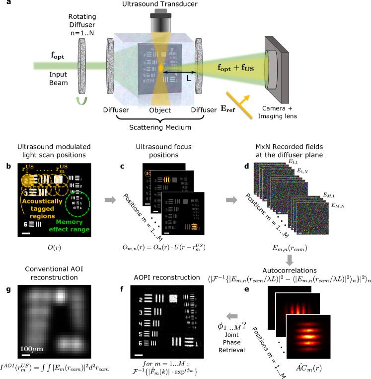
The principle of our approach is presented in Figure 1 along with a numerical example. Our approach is based on a conventional pulsed AOI setup, employing a camera-based holographic detection of the ultrasound modulated light [8, 18]. In this setup (Fig. 1(a)) the sample is illuminated by a pulsed quasi-monochromatic light beam at a frequency . The diffused light is ultrasonically tagged at a chosen position inside the sample by a focused ultrasound pulse at a central frequency . The acousto-optic modulated (ultrasound-tagged) light field at frequency is measured by a camera placed outside the sample using a pulsed reference beam that is synchronized with the ultrasound pulses, via off-axis phase-shifting interferometry [20, 30] (Supplementary section 1).
In conventional AOI, the ultrasound focus is scanned along the target object (Fig. 1(b,c)), and the AOI image, , is formed by summing the total power of the detected ultrasound-modulated light at each ultrasound focus position : , where is the ultrasound-modulated speckle field that is measured by the camera (Fig. 1(d)). Since the conventional AOI image (Fig. 1(g)) is a convolution between the target object and the ultrasound-focus pressure distribution [20], its resolution is limited by the acoustic diffraction limit.
Our approach relies on the same data acquisition scheme as in conventional AOI (Fig. 1(b-d)). However, instead of integrating the total power of the camera-detected ultrasound-modulated field at each ultrasound position, we use the spatial information in the detected field, , to reconstruct the diffraction-limited target features inside the ultrasound focus, via speckle-correlation computational imaging approach [23, 24, 31]. Specifically, we estimate the autocorrelations of the hidden target inside each ultrasound focus position (Fig. 1(e)), and then use a ptychography-based algorithm [27, 28] to jointly reconstruct the entire target from all estimated autocorrelations (Fig. 1(f)). Thus, our approach exploits the richness in the information of the detected ultrasound-modulated speckle fields, which contain a number of speckle grains limited only by the camera pixel count.
Beyond improving the resolution of AOI by several orders of magnitude, from the ultrasound diffraction-limit to the optical diffraction limit, our approach allows to tackle a fundamental and generally very difficult to fulfill a requirement for speckle-correlation imaging: that the entire imaged object area must be contained within the memory-effect correlation-range [32, 24, 23], i.e. that all object points produce correlated speckle patterns [24]. This requirement usually limits speckle-correlation imaging to small and unnaturally-isolated objects. Recently, ptychography-based approaches were utilized to overcome the memory-effect FoV [33, 34]. However, the implementations of all FoV-extending approaches to date required direct access to the target in order to limit the illuminated area, a requirement that is impossible to fulfill in noninvasive imaging applications. Our approach overcomes this critical obstacle by relying on noninvasive ultrasound tagging to limit the detected light to originate only from a small controlled volume that is determined by the ultrasound focus. The only requirement for speckle-correlation imaging is that the ultrasound focus (Fig. 1(b), dashed yellow circle) would be smaller than the memory-effect range (Fig. 1(b), dashed green circle). Thus allowing to image through scattering layers objects that extend well beyond the memory-effect FoV, without a limit on their total dimensions.
Mathematically our approach can be described as follows: Consider a target object located inside a scattering sample (Fig. 1(a)). As a simple model, we model the object by a thin 2D amplitude and a phase mask, whose complex field transmission is given by . The goal of our work is to reconstruct the object 2D transmission by noninvasive measurements of the scattered light distributions outside the sample. A monochromatic spatially-coherent laser beam illuminates the object through the scattering sample (Fig. 1(a)). The light propagates through the scattering sample, results in a speckle illumination pattern at the object plane. Considering a dynamic scattering sample, such as biological tissue, the illuminating speckle pattern on the object is time-varying. We denote the speckle pattern field illuminating the object at a time by . The field distribution of the light that traverses the object at time is thus given by: . This light pattern is ultrasound modulated by an ultrasound focus whose central position, , is scanned over positions inside the sample. We denote the ultrasound focus pressure distribution at the m-th position by . The shift-invariance of the ultrasound focus is assumed here for simplicity of the derivation, and is not a necessary requirement [35]. The ultrasound modulated light field at the m-th ultrasound focus position is given by the product of and : . The ultrasound modulated light field propagates to the camera through the scattering sample, producing a random speckle field at the camera plane: . When the ultrasound focus dimensions are smaller than the memory-effect range: , where is the depth of the object inside the scattering sample from the camera side (Fig. 1(a)) and is the angular range of the memory effect, the scattering sample can be considered as a thin random phase-mask with a phase distribution . The scattered light field measured by a camera that images the scattering sample facet is thus given by:
| (1) |
where is the propagation operator for propagating the field from the object plane to the scattering sample facet. The complex field autocorrelation of the target, illuminated by the n-th speckle pattern and multiplied by the ultrasound field distribution can be calculated from a single camera frame [36]. However, multiple () camera frames, captured under different speckle illuminations, can be used to calculate the target intensity autocorrelation: , which is free from speckle artefacts via correlography [36], in the exact same manner as demonstrated without ultrasound modulation by Edrei et al [31]. In correlography [36, 31, 34] the estimate for the object un-speckled intensity autocorrelation at the m-th ultrasound focus position, , is calculated by averaging the Fourier transforms of the captured speckle frames intensity distribution, after subtracting their mean value [36, 34]:
| (2) | |||
The calculated autocorrelation, , is the autocorrelation of the object convolved with the diffraction-limited point-spread-function of the imaging aperture on the facet plane. A required condition for estimating the object autocorrelation from the Fourier-transform of the captured speckle patterns (Eq.2) is that the object distance from the measurement plane, , is larger than , where D is the object dimensions, i.e. the ultrasound focus diameter, and is the illumination speckle grain size [31]. In deep tissue imaging, , and the condition becomes: , i.e. the imaging depth should be larger than the dimensions of the ultrasound focus, a naturally fulfilled condition.
The use of a multiple illumination speckle realizations, , is advantageous both for estimating the un-speckled intensity transmission of the object, , and for improved ensemble averaging of the estimation [24, 31] (see Supplementary section 5). For a dynamic sample, the speckle illuminations naturally vary in time, and in the case of a static sample, the speckle realizations can be easily obtained by e.g. a rotating diffuser. According to the Wiener-Khinchin theorem, the Fourier transform of the object estimated autocorrelation, , is the Fourier magnitude of the object intensity transmission: The object itself can thus be reconstructed from via phase retrieval [37].
| (3) |
If a partial overlap between the scanned ultrasound foci exists, the reconstruction problem can be reliably solved using ptychography, an advanced joint phase-retrieval technique [38, 27, 28, 29], that was recently shown to be extremely successful in stable, high-fidelity, robust reconstruction of complex objects, which is not possible by separately solving the phase-retrieval problem. A numerical example for using our approach to image an extended object beyond the memory-effect FoV, with diffraction-limited resolution is shown in Fig 1.f, side-by-side with the conventional AOI image of the same object using the same measurements (Fig. 1(g)). A resolution increase of over conventional AOI is apparent in the high-fidelity reconstruction (Fig. 1(f)). A detailed explanation of the data processing and the implemented ptychographic reconstruction algorithm can be found in Supplementary section 4,7.
3 Results
3.1 Experimental set up
To demonstrate our approach we built a proof-of-principle setup schematically shown in Fig. 1(a). It is a conventional AOI setup with camera-based holographic detection based on phase-shifting off-axis holography (Supplementary section 1), with the addition of a controlled rotating diffuser before the sample (two light shaping diffusers, Newport), used for generating dynamic random speckle illumination. The illumination is provided by a pulsed long-coherence laser at a wavelength of 532nm (Standa). An ultrasound transducer with a central frequency of , and ultrasound focus dimensions of , full-width at half max (FWHM) in the horizontal (transverse) and vertical (axial ultrasound) directions, correspondingly, is used for acousto-optic modulation. The ultrasound focus position was scanned laterally by a motorized stage, and axially by electronically varying the time delay between the laser and ultrasound pulses. The full setup description is given in Supplementary Section 1. As controlled scattering samples and imaged targets for our proof-of-principle experiments we used a sample comprised of a target placed in water between two scattering layers composed of several scattering diffusers that have no ballistic component (see Supplementary Section 6). An sCMOS camera (Andor Zyla 4.2 plus) was used to holographically record the ultrasound-modulated scattered light fields, using a frequency-shifted beam. To minimize distortions in the recorded fields, no optical elements were present between the camera and the diffuser. The field at the diffuser plane, , was calculated from the camera recorded field by digital propagation (Supplementary section 1).
3.2 Imaging an extended object beyond the memory effect
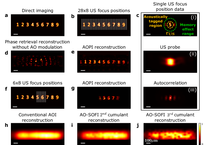
As a first demonstration, we imaged a transmittive target composed of nine digits (Fig. 2(a)) that extends over times beyond the memory-effect of the scattering sample, which is (Fig. 2(c(i)), dashed green circle, Supplementary Fig. S3).
For 2D imaging, the ultrasound focus (Fig. 2(c(ii))) was scanned over the target with a step size of ,, in the horizontal and vertical directions, respectively. These steps (along with the ultrasound spot size) define a probe overlap of between neighboring positions (Fig. 2(b)). A study of the effect of the probe overlap on the reconstruction fidelity is presented in Supplementary section 8. For each ultrasound focus position, () we recorded different ultrasound-modulated light fields, , each with a different (unknown) speckle realization, . The target was reconstructed from the autocorrelations using rPIE ptychographic algorithm [28] (Supplementary section 7). Fig. 2(c(iii)) presents an example for one of the autocorrelations used as input. The AOPI reconstructed image (Fig. 2(e)) provide an image with a resolution well beyond that of a conventional AOI reconstruction (Fig. 2(h)), and also well beyond the improved resolution of recent super-resolution AOI techniques such as AO-SOFI [20] (Fig. 2(i-j)). Importantly, since the target extends beyond the memory-effect range, as is the case in many practical imaging scenarios, conventional speckle-correlation imaging without AO modulation [31, 24] fail to reconstruct the object (Fig. 2(d)), as expected. Interestingly, when taken only part of the measured positions from the center of the scanned area (only positions from the center of the object area, instead of all positions, Fig. 2(f)), and reconstruct the probed object - a good reconstruction is obtained using AOPI method (Fig. 2(g)), proving that the acoustic probe well functions as an isolation aperture.
3.3 Imaging resolution verification
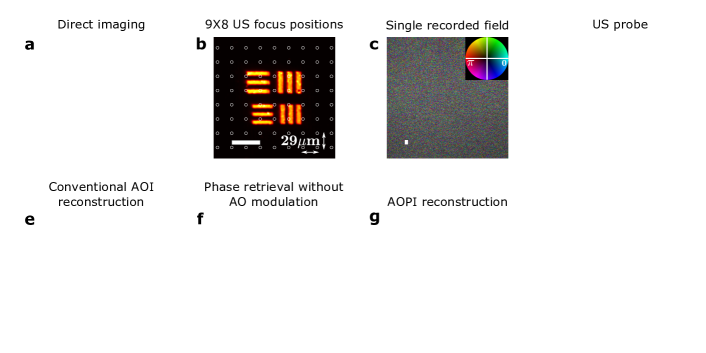
To demonstrate the resolution increase of AOPI we performed an additional experiment where the target of Fig. 2 was replaced by elements 3-4 of group 6 of a negative USAF-1951 resolution test chart (Fig. 3(a)). For 2D imaging, the ultrasound focus ( Fig. 3(d)) was scanned over the target with a step size of . These steps (along with the ultrasound spot size) define a probe overlap of between neighbouring positions (Fig. 3(b)). For each ultrasound focus position, , we recorded different ultrasound-modulated light fields, (Fig 3.c), each with a different (unknown) speckle realization, . The reconstruction of the target from the autocorrelations using rPIE ptychography algorithm [28] is presented in Fig. 3(g-h). A study of the effect of probe overlap on the reconstruction is presented in Supplementary section 8. The AOPI reconstructed image resolves resolution target features of size (separation) of (Fig. 3(g-h)), which is smaller than the acoustic focus FWHM (). The cross-sections of the reconstructed image (Fig. 3(h)) allow to estimate the imaging resolution by fitting the result to a convolution of the known sample structure with a Gaussian PSF. This results in a resolution of (FWHM), a 40-fold increase in resolution compared to the acoustic resolution of conventional AOI (Fig. 3(e)). Interestingly, although the target dimensions in this experiment are contained in the memory-effect range, conventional speckle-correlation imaging that is based on phase-retrieval without AO modulation (Fig. 3(f)), results in a considerably lower reconstruction fidelity than the AOPI reconstruction (Fig. 3(g)). This improvement is attributed to the larger input data set and improved algorithmic stability of ptychographic reconstruction compared to simple phase-retrieval [38, 27].
4 Discussion and conclusion
We proposed and demonstrated an approach for diffraction-limited wide FoV optical imaging in ultrasound with speckle-correlation computational imaging [31]. In contrast to previous approaches for super-resolved acousto-optic imaging [17, 18, 16, 15], the resolution of our approach is optically diffraction-limited, independent of the ultrasound probe dimensions, the ratio between the speckle grain size and the ultrasound probe dimensions, or the number of realizations[18]. This allowed us to demonstrate an improvement in resolution over the acoustic diffraction-limit, an order of magnitude larger gain in resolution compared to the state of the art approaches, such as iTRUE [16, 15], TROVE [17], and AOTM [18]. In addition, TROVE and AOTM allow the resolution to increase only when unrealistically large speckle grains are considered [18].
Another important advantage of our approach is that unlike transmission-matrix and wavefront-shaping based approaches [17, 18] it does not require unrealistically long speckle decorrelation times. Similar to recent approaches that utilize random fluctuations [20, 34], our approach benefits from the natural speckle decorrelation to generate independent realizations of coherent illumination, improving the estimation of the object autocorrelation [31].
While our approach relies on the memory-effect to retrieve the diffraction-limited image, its FoV is not limited by the memory-effect range, as is the case in all other noninvasive memory-effect based techniques [23, 24]. The FoV is dictated by the scanning range of the ultrasound focus, which is practically limited only by the allowed acquisition time. Such an extension of the FoV in speckle-correlation based imaging has only been obtained before by invasive access to the target object [39, 33, 40, 41]. The adaptation of a ptychographic image reconstruction significantly improves the reconstruction fidelity and stability compared to phase-retrieval reconstruction (Fig. 3(f-g)) [24, 23].
Our super-resolution AOPI approach does not rely on wavefront-shaping [17, 15, 16, 18] or nonlinear effects[42], and it can be applied to any AOI system employing camera-based coherent detection.
The main limitation of our approach is the requirement for a memory-effect range which is of the order of the ultrasound probe dimensions, i.e. that the ultrasound-tagged fields have a non-negligible correlations. This condition can be satisfied by relying on a small ultrasound focus, achieved by the use of high-frequency ultrasound, and by the use of long laser wavelength, which increases the memory-effect range [43, 32]. Importantly, while at very large imaging depths, deep within the diffusive light propagation regime, the memory effect angular range is [43, 32], at millimeter-scale depths, which are of the order of the transport mean free path (TMFP), the memory-effect range has been shown to be orders of magnitude larger [44]. In addition, the requirement for a sufficiently large memory-effect can be alleviated by relying on translation-correlations [25] or the generalized memory-effect [26]. Applying the above improvements (a higher ultrasound frequency, a longer optical wavelength, generalized speckle correlations) are the next steps for bringing our proof of principle demonstrations to practical biomedical imaging applications.
Another necessary technical improvement for biomedical application of our approach is in the demonstrated acquisition speed. Similar to all super-resolution techniques that do not rely on object priors, our approach requires a large number of measurements for reconstructing a single image. The required number of frames is the product of: (the number of probe positions) (the number of realization per probe position) (number of phase-shifting frames). In our proof of principle demonstration system, which was not optimized for acquisition speed, we used 150 realizations per probe position and 16 phase-shifting frames. A diffuser mounted on a slowly rotating motor was used to change the realizations, and a conventional sCMOS camera was used to capture the images, which resulted in an acquisition time of seconds per realization. This time can be reduced by orders of magnitude using single-shot, off-axis, fast camera-based detection [45, 18, 46, 21], a fast MEMS-based dynamic wavefront randomizer [47], and 2D electronic scanning US array instead of the mechanical scan of the single-element ultrasound transducer [48]. Assuming the acquisition speed is limited by the camera frame-rate of frames-per-second [18], the acquisition of 150 realizations for 72 probe positions (as in Fig. 3), will be of the order of , excluding off-line data processing. This is expected to be adequate for imaging biological structures since the requirement on the speckle decorrelation time is that of a single frame, i.e. . Moreover, the number of required realizations is expected to be significantly reduced by using advanced correlation-based reconstruction schemes such as those provided by deep neural networks (DNN). These have been recently shown to be able to significantly improve the estimation of the intensity autocorrelation, from only a few coherent realizations [49].
The combination of the state-of-the-art optical, ultrasound, and computational imaging approaches, has the potential to significantly impact imaging deep inside complex samples.
5 Funding
European Research Council (ERC) Horizon 2020 research and innovation program (grant no. 677909), Azrieli foundation, Israel Science Foundation (1361/18),Israeli Ministry of Science and Technology, National Science Foundation (1813848).
6 Acknowledgments
We thank Prof. Hagai Eisensberg for the q-switched laser and thank the Nanocenter at the Hebrew University, with special thanks to Dr. Itzik Shweky and Galina Chechelinsky, for fabrication the target samples.
7 Disclosures
Disclosures. The authors declare no conflicts of interest.
References
- [1] V. Ntziachristos, “Going deeper than microscopy: the optical imaging frontier in biology,” \JournalTitleNature methods 7, 603–614 (2010).
- [2] J. Pawley, Handbook of biological confocal microscopy, vol. 236 (Springer Science & Business Media, 2006).
- [3] R. H. Webb, “Confocal optical microscopy,” \JournalTitleReports on Progress in Physics 59, 427 (1996).
- [4] D. Huang, E. A. Swanson, C. P. Lin, J. S. Schuman, W. G. Stinson, W. Chang, M. R. Hee, T. Flotte, K. Gregory, C. A. Puliafito et al., “Optical coherence tomography,” \JournalTitlescience 254, 1178–1181 (1991).
- [5] A. F. Fercher, W. Drexler, C. K. Hitzenberger, and T. Lasser, “Optical coherence tomography-principles and applications,” \JournalTitleReports on progress in physics 66, 239 (2003).
- [6] W. Drexler and J. G. Fujimoto, Optical coherence tomography: technology and applications (Springer Science & Business Media, 2008).
- [7] M. Jang, H. Ko, J. H. Hong, W. K. Lee, J.-S. Lee, and W. Choi, “Deep tissue space-gated microscopy via acousto-optic interaction,” \JournalTitleNature communications 11, 1–11 (2020).
- [8] D. S. Elson, R. Li, C. Dunsby, R. Eckersley, and M.-X. Tang, “Ultrasound-mediated optical tomography: a review of current methods,” \JournalTitleInterface Focus 1, 632–648 (2011).
- [9] L. V. Wang, “Ultrasound-mediated biophotonic imaging: a review of acousto-optical tomography and photo-acoustic tomography,” \JournalTitleDisease markers 19, 123–138 (2004).
- [10] S. G. Resink, W. Steenbergen, and A. C. Boccara, “State-of-the art of acoust-optic sensing and imaging of turbid media,” \JournalTitleJournal of biomedical optics 17, 040901 (2012).
- [11] L. V. Wang and S. Hu, “Photoacoustic tomography: in vivo imaging from organelles to organs,” \JournalTitlescience 335, 1458–1462 (2012).
- [12] Y. Liu, P. Lai, C. Ma, X. Xu, A. A. Grabar, and L. V. Wang, “Optical focusing deep inside dynamic scattering media with near-infrared time-reversed ultrasonically encoded (true) light,” \JournalTitleNature communications 6, 1–9 (2015).
- [13] Y. M. Wang, B. Judkewitz, C. A. DiMarzio, and C. Yang, “Deep-tissue focal fluorescence imaging with digitally time-reversed ultrasound-encoded light,” \JournalTitleNature communications 3, 1–8 (2012).
- [14] K. Si, R. Fiolka, and M. Cui, “Fluorescence imaging beyond the ballistic regime by ultrasound-pulse-guided digital phase conjugation,” \JournalTitleNature photonics 6, 657–661 (2012).
- [15] K. Si, R. Fiolka, and M. Cui, “Breaking the spatial resolution barrier via iterative sound-light interaction in deep tissue microscopy,” \JournalTitleScientific reports 2, 748 (2012).
- [16] H. Ruan, M. Jang, B. Judkewitz, and C. Yang, “Iterative time-reversed ultrasonically encoded light focusing in backscattering mode,” \JournalTitleScientific reports 4, 7156 (2014).
- [17] B. Judkewitz, Y. M. Wang, R. Horstmeyer, A. Mathy, and C. Yang, “Speckle-scale focusing in the diffusive regime with time reversal of variance-encoded light (trove),” \JournalTitleNature photonics 7, 300–305 (2013).
- [18] O. Katz, F. Ramaz, S. Gigan, and M. Fink, “Controlling light in complex media beyond the acoustic diffraction-limit using the acousto-optic transmission matrix,” \JournalTitleNature communications 10, 1–10 (2019).
- [19] M. Cui and C. Yang, “Implementation of a digital optical phase conjugation system and its application to study the robustness of turbidity suppression by phase conjugation,” \JournalTitleOptics express 18, 3444–3455 (2010).
- [20] D. Doktofsky, M. Rosenfeld, and O. Katz, “Acousto optic imaging beyond the acoustic diffraction limit using speckle decorrelation,” \JournalTitleCommunications Physics 3, 1–8 (2020).
- [21] H. Ruan, Y. Liu, J. Xu, Y. Huang, and C. Yang, “Fluorescence imaging through dynamic scattering media with speckle-encoded ultrasound-modulated light correlation,” \JournalTitleNature Photonics pp. 1–6 (2020).
- [22] S. Feng, C. Kane, P. A. Lee, and A. D. Stone, “Correlations and fluctuations of coherent wave transmission through disordered media,” \JournalTitlePhysical review letters 61, 834 (1988).
- [23] J. Bertolotti, E. G. Van Putten, C. Blum, A. Lagendijk, W. L. Vos, and A. P. Mosk, “Non-invasive imaging through opaque scattering layers,” \JournalTitleNature 491, 232–234 (2012).
- [24] O. Katz, P. Heidmann, M. Fink, and S. Gigan, “Non-invasive single-shot imaging through scattering layers and around corners via speckle correlations,” \JournalTitleNature photonics 8, 784–790 (2014).
- [25] B. Judkewitz, R. Horstmeyer, I. M. Vellekoop, I. N. Papadopoulos, and C. Yang, “Translation correlations in anisotropically scattering media,” \JournalTitleNature physics 11, 684–689 (2015).
- [26] G. Osnabrugge, R. Horstmeyer, I. N. Papadopoulos, B. Judkewitz, and I. M. Vellekoop, “Generalized optical memory effect,” \JournalTitleOptica 4, 886–892 (2017).
- [27] A. M. Maiden and J. M. Rodenburg, “An improved ptychographical phase retrieval algorithm for diffractive imaging,” \JournalTitleUltramicroscopy 109, 1256–1262 (2009).
- [28] A. Maiden, D. Johnson, and P. Li, “Further improvements to the ptychographical iterative engine,” \JournalTitleOptica 4, 736–745 (2017).
- [29] M. Pham, A. Rana, J. Miao, and S. Osher, “Semi-implicit relaxed douglas-rachford algorithm (sdr) for ptychography,” \JournalTitleOptics express 27, 31246–31260 (2019).
- [30] M. Gross, P. Goy, B. Forget, M. Atlan, F. Ramaz, A. Boccara, and A. Dunn, “Heterodyne detection of multiply scattered monochromatic light with a multipixel detector,” \JournalTitleOptics letters 30, 1357–1359 (2005).
- [31] E. Edrei and G. Scarcelli, “Optical imaging through dynamic turbid media using the fourier-domain shower-curtain effect,” \JournalTitleOptica 3, 71–74 (2016).
- [32] I. Freund, “Looking through walls and around corners,” \JournalTitlePhysica A: Statistical Mechanics and its Applications 168, 49–65 (1990).
- [33] D. F. Gardner, S. Divitt, and A. T. Watnik, “Ptychographic imaging of incoherently illuminated extended objects using speckle correlations,” \JournalTitleApplied optics 58, 3564–3569 (2019).
- [34] Z. Li, D. Wen, Z. Song, T. Jiang, W. Zhang, G. Liu, and X. Wei, “Imaging correlography using ptychography,” \JournalTitleApplied Sciences 9, 4377 (2019).
- [35] I. Peterson, R. Harder, and I. Robinson, “Probe-diverse ptychography,” \JournalTitleUltramicroscopy 171, 77–81 (2016).
- [36] P. S. Idell, J. R. Fienup, and R. S. Goodman, “Image synthesis from nonimaged laser-speckle patterns,” \JournalTitleOptics letters 12, 858–860 (1987).
- [37] J. R. Fienup, “Reconstruction of an object from the modulus of its fourier transform,” \JournalTitleOptics letters 3, 27–29 (1978).
- [38] J. M. Rodenburg and H. M. Faulkner, “A phase retrieval algorithm for shifting illumination,” \JournalTitleApplied physics letters 85, 4795–4797 (2004).
- [39] G. Li, W. Yang, H. Wang, and G. Situ, “Image transmission through scattering media using ptychographic iterative engine,” \JournalTitleApplied Sciences 9, 849 (2019).
- [40] M. Zhou, R. Li, T. Peng, A. Pan, J. Min, C. Bai, D. Dan, and B. Yao, “Retrieval of non-sparse objects through scattering media beyond the memory effect,” \JournalTitleJournal of Optics 22, 085606 (2020).
- [41] S. Divitt, D. F. Gardner, and A. T. Watnik, “Imaging around corners in the mid-infrared using speckle correlations,” \JournalTitleOptics Express 28, 11051–11064 (2020).
- [42] J. Selb, L. Pottier, and A. C. Boccara, “Nonlinear effects in acousto-optic imaging,” \JournalTitleOptics letters 27, 918–920 (2002).
- [43] I. Freund, M. Rosenbluh, and S. Feng, “Memory effects in propagation of optical waves through disordered media,” \JournalTitlePhysical review letters 61, 2328 (1988).
- [44] S. Schott, J. Bertolotti, J.-F. Léger, L. Bourdieu, and S. Gigan, “Characterization of the angular memory effect of scattered light in biological tissues,” \JournalTitleOptics express 23, 13505–13516 (2015).
- [45] Y. Liu, C. Ma, Y. Shen, J. Shi, and L. V. Wang, “Focusing light inside dynamic scattering media with millisecond digital optical phase conjugation,” \JournalTitleOptica 4, 280–288 (2017).
- [46] Y. Liu, Y. Shen, C. Ma, J. Shi, and L. V. Wang, “Lock-in camera based heterodyne holography for ultrasound-modulated optical tomography inside dynamic scattering media,” \JournalTitleApplied physics letters 108, 231106 (2016).
- [47] F. Shevlin, “Phase randomization for spatiotemporal averaging of unwanted interference effects arising from coherence,” \JournalTitleApplied optics 57, E6–E10 (2018).
- [48] J.-B. Laudereau, A. A. Grabar, M. Tanter, J.-L. Gennisson, and F. Ramaz, “Ultrafast acousto-optic imaging with ultrasonic plane waves,” \JournalTitleOptics Express 24, 3774–3789 (2016).
- [49] C. A. Metzler, F. Heide, P. Rangarajan, M. M. Balaji, A. Viswanath, A. Veeraraghavan, and R. G. Baraniuk, “Deep-inverse correlography: towards real-time high-resolution non-line-of-sight imaging,” \JournalTitleOptica 7, 63–71 (2020).
See pages - of supp.pdf