Abnormal topological refraction into free medium at sub-wavelength scale
in valley phononic crystal plates
Abstract
In this work we propose a topological valley phononic crystal plate and we extensively investigate the refraction of valley modes into the surrounding homogeneous medium. This phononic crystal includes two sublattices of resonators (A and B) modeled by mass-spring systems. We show that two edge states confined at the AB/BA and BA/AB type domain walls exhibit different symmetries in physical space and energy peaks in the Fourier space. As a result, distinct refraction behaviors, especially through an armchair cut edge, are observed. On the other hand, the decay depth of these localized topological modes, which is found to be solely determined by the relative resonant strength between the scatterers, significantly affects the refraction patterns. More interestingly, the outgoing traveling wave through a zigzag interface becomes evanescent when operating at deep sub-wavelength scale. This is realized by tuning the average resonant strength. We show that the evanescent modes only exist along a particular type of outlet edge, and that they can couple with both topological interface states. We also present two designs of topological functional devices, including an elastic one-way transmission waveguide and a near-ideal monopole/dipole emitter, both based on our phononic structure.
I Introduction
Recent advances in topological condensed matter physics have drawn growing attention in the scientific community, due to the excellent performance in wave manipulation, such as the suppression and immunity against sharp bends and defects along the interface or boundary, which is the key feature of topological protection. The quantum physics originated concepts have been recently extended to the field of classical wave systems through mimicking the quantum Hall effect (QHE) Haldane and Raghu (2008); Lu et al. (2014a); Khanikaev et al. (2015); Yang et al. (2015); Ding et al. (2019); Nash et al. (2015); Wang et al. (2015), the quantum spin Hall effect (QSHE) Mousavi et al. (2015); He et al. (2016); Mei et al. (2016); Yves et al. (2017); Miniaci et al. (2018); Xia et al. (2017); Chaunsali et al. (2018); Yu et al. (2018); Yang et al. (2018) or the quantum valley Hall effect (QVHE) Lu et al. (2017); Gao et al. (2018); Wu et al. (2018); Makwana and Craster (2018); Zhu et al. (2019); Xie et al. (2019); Wang et al. (2019a, b); Zhang et al. (2020).
The realization of classical analogues of QHE requires breaking the time-reversal symmetry (TRS), which can be achieved by applying a magnetic field in photonic systems Haldane and Raghu (2008); Lu et al. (2014a). For acoustic or mechanical systems, active components such as circulating fluid flows Khanikaev et al. (2015); Yang et al. (2015); Ding et al. (2019) or gyroscopes Nash et al. (2015); Wang et al. (2015) have been proposed to create such an effective "magnetic" field to break the TRS. But this strategy still remains challenging due to the structural complexity. Mimicking QSHE or QVHE in classical waves by breaking the symmetry does not require any external fields. Unlike in electronic crystals, though half integer spin induced Kramers degeneracy is not guaranteed in photonic or phononic systems as they are bosonic, classical analogues of QSHE can be achieved by carefully designing the system to have two pseudospins, either by integrating the different wave polarization degree of freedom (DOF) Mousavi et al. (2015); Miniaci et al. (2018); Wang et al. (2019a) or by folding the band structure He et al. (2016); Mei et al. (2016); Yves et al. (2017); Xia et al. (2017); Chaunsali et al. (2018); Yu et al. (2018); Yang et al. (2018) to form a double Dirac cone. In addition, the valley index in solid-state materials can be viewed as a new carrier of information by emulating QVHE, originated from the valley DOF of electrons in graphene Xiao et al. (2007), can be achieved by breaking the spatial inversion symmetry (IS) Lu et al. (2017); Gao et al. (2018); Wu et al. (2018); Makwana and Craster (2018); Zhu et al. (2019); Xie et al. (2019); Wang et al. (2019a, b); Zhang et al. (2020).
Though a variety of topological phases have been demonstrated, most of the current studies concentrate on the robust wave propagation along the topological domain walls inside the lattice structures Khanikaev et al. (2015); Yang et al. (2015); Ding et al. (2019); Nash et al. (2015); Wang et al. (2015); Mousavi et al. (2015); He et al. (2016); Mei et al. (2016); Yves et al. (2017); Miniaci et al. (2018); Xia et al. (2017); Chaunsali et al. (2018); Yu et al. (2018); Yang et al. (2018); Lu et al. (2017); Wu et al. (2018); Makwana and Craster (2018); Wang et al. (2019b); Zhang et al. (2020); Wang et al. (2020). However, for applicable topological devices in reality, the finite size and boundary effects of the lattices also need to be taken into consideration. Perhaps the most concerned issue is how the topological edge waves would be transmitted into the surrounding homogeneous medium. Various outcoupling effects, such as topological positive/negative, near-zero refraction and wave splitting have recently been reported in valley phononic crystal (PnC) s Gao et al. (2018); Zhu et al. (2019); Xie et al. (2019); Wang et al. (2019a), Weyl PnC He et al. (2018), and QSHE inspired PnC s Zhang et al. (2017); Huang et al. (2020).
In this article, we extensively investigate the topological refraction in valley PnC s. We examine the refraction behaviors of the symmetric and antisymmetric valley modes confined along different domain walls through zigzag and armchair outlet edges, with the influence of both decay depth and Dirac frequency range taken into consideration. Abnormal refraction patterns arise in some cases. When the edge modes are strongly localized, the refracted field spreads in a large area in the background (see Fig.4(c)), different from what can be estimated from phase matching conditions (see Fig.4(a)). Likewise, in the sub-wavelength regime, refraction of the expected evanescent waves is forbidden, resulting in strong local resonances and in turn to radiation of elastic energy in the background by the nearly perfect monopoles and/or dipoles formed by the resonators on the edge.
The article is organized as follows: in section II, we present the elastic plate model with honeycomb lattice of mass-spring resonators attached on the top face, and we illustrate the dispersion curves for flexural wave. The perturbation method is used to develop the effective Hamiltonian characterizing the band structure and topological properties. We also describe the multiple scattering theory (MST) for wave field responses under any incident wave. In section III, we show the existence of a pairs of edge states confined at the topological domain walls. Various topological refraction patterns are detailed and discussed. In section IV we present two examples of possible functional topological devices, including a one-way transmission elastic waveguide and a near perfect monopole/dipole emitter. Finally, the main results of this work and conclusions are summarized in section V.
II formulation and methods
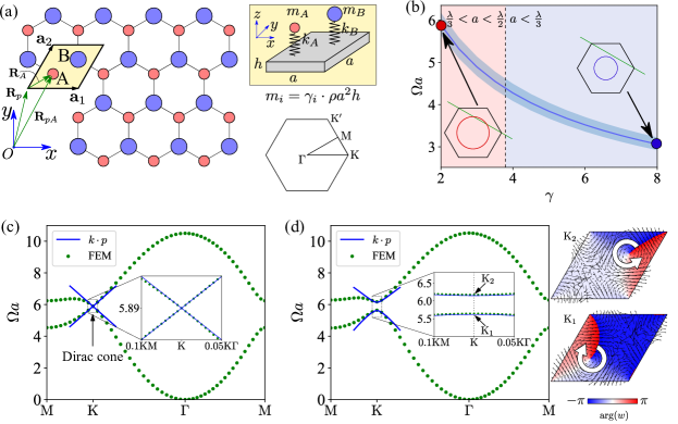
We consider the flexural wave propagation problem in a PnC with a honeycomb lattice of mass-spring resonators attached to the top face of an elastic plate, as shown in Fig.1 (a). The lattice constant and the thickness of the PnC are and , respectively. The plate material is supposed to be aluminum, with Young’s modulus , Poisson’s ratio and mass density . Each unit cell consists of two distinct resonators, or "artificial atoms", characterized by their masses and stiffnesses (). For simplicity we let all the spring stiffnesses being identical, so the mass term becomes the only varying parameter that enables our system to exhibit different symmetries. Here we define a non-dimensionalized factor to describe the system’s mass degree of freedom as
| (1) |
or equivalently , where is the averaged mass and is the mass difference which plays the role of a perturbation. The unperturbed system sustains a pair of linearly crossing gapless dispersion curves at each irreducible Brillouin zone (IBZ) corner, forming a Dirac cone which is guaranteed by the and point group symmetries of the PnC and point in the reciprocal space according to group theory (Lu et al., 2014b). The gapping of the Dirac cone is achieved via a symmetry reduction from to (Makwana and Craster, 2018) by introducing a small perturbation which breaks the spatial IS.
II.1 Band structure
The flexural wave modes in elastic thin plates are characterized by the out-of-plane displacement field . According to Kirchhoff–Love (K-L) plate theory, the time-harmonic field is governed by
| (2) |
where is the plate flexural rigidity, is the biharmonic operator, is the angular frequency, and is the reaction force from the mass-spring resonators,
| (3) |
in which the summation index labels each elementary cell. This periodic repeating creates the infinite PnC. represents the flexural wave field at position , is the resonant frequency of resonator , and is Dirac delta function. In this article we assume that the resonance frequencies of the mass-spring resonators are much higher than the working frequency we are interested in. In the calculation we have set the spring stiffness to be infinite large (), which corresponds to the situation that the masses are attached directly to the plate surface. This does not affect our understanding of the mechanisms of the topological transport and refraction into the surrounding homogeneous plate (HP), and keeps our model simple without introducing unnecessary additional resonance features. The corresponding reaction force in Eq.(3) can be further simplified as
| (4) |
According to the Bloch theory, the eigenmodes of the flexural wave in periodic PnC plates can be expressed as
| (5) |
where is the corresponding cell-periodic counterpart of the Bloch state, is an arbitrary wave vector in the IBZ and labels the eigenfrequency index. To obtain the band structure, Eq.(2) must be solved in the infinite two dimensional system. Due to the periodicity, Bloch theory Eq.(5) enables us to limit the solution domain to only one unit cell, together with a quasi-periodic boundary condition . This eigenvalue problem is then solved by using the plate interface of COMSOL Multiphysics, a commercial finite element method (FEM) software. The mass-spring is modeled by applying frequency-dependent forces using Eq.(4) along vertical axis and an antisymmetric condition is applied on the mid-plane to identify the flexural modes only. Some other approaches for band structure calculations, such as plane wave expansion method, can be found in Refs. (Torrent et al., 2013; Pal and Ruzzene, 2017; Chaunsali et al., 2018). It is also useful to introduce a normalized frequency , where is defined as
| (6) |
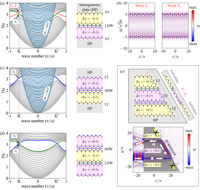
We first calculate the band structure of an unperturbed system with , as depicted in Fig.1(c). As expected, the first two bands linearly cross each other at the normalized frequency , forming a Dirac cone at the IBZ corner . The inset shows a comparison between the first principle FEM calculated dispersion curves (green dots) and the analytical results (blue solid lines) derived from an effective Hamiltonian by perturbation method (see section II.2). Then a level of perturbation is introduced to gap the Dirac cone and open a topological band gap, as plotted in Fig.1(d). The gapped band structure acts as a local quadratic function of wave vector according to our later analysis, which accurately captures the band diagrams near point. The phase distributions and time-averaged energy flux of these two lifted degenerate states ( and ) are displayed in the right panel of Fig.1(d), which reveals that they can be regarded as valley pseudospin states based on the vortex chirality. The features of valley , the time-reversal counterpart of , can be deduced in a similar way. If we change the sign of mass perturbation, the chiralities of these two lifted states would reverse, which is typically a clue for topological transition. To unambiguously reveal the topological properties of these bands, we use in section II.2 the perturbation method to give an analytical expression of the reduced effective Hamiltonian, and obtain the expression of the valley Chern numbers.
It has been demonstrated that the perturbation is responsible for the splitting of Dirac cone and the opening of topological band gaps. One may wonder how the average mass affects the PnC’s behaviors. In fact, can be used to tune the Dirac frequency within a certain range. Actually, it can be seen from Fig.1(b) that decreases as increases. At a certain value of (vertical dashed line), the line connecting two points in the reciprocal space is tangent to the equifrequency contour computed in the HP. Here this line represents the normal of a zigzag outlet edge of a finite sized lattice. Below this critical (light red area), the interface normal has intersection points with the equifrequency contour. According to the conservation law of wave vector along the tangent direction of the interface, the direction joining this intersection point to the origin represents the propagation direction of the refracted wave. However, above this critical (light blue area), we arrive at a deeper sub-wavelength scale () in which the normal to the interface has no intersections with the equifrequency contour. It means that we cannot find a wave vector in the HP that fulfills the conservation law of wave vector along the tangent direction of the interface. In other words, the (or ) locked states which propagate inside a lattice cannot refract into a traveling wave into the HP when leaving the outlet edge at the current orientation. In section III we discuss in detail these different refraction patterns ranging from traveling wave to evanescent wave as the Dirac frequency decreases.
II.2 Effective Hamiltonian by perturbation
In this section we show how the biharmonic wave equation Eq.(2) in the periodic PnC can be mapped into a massless and massive Dirac Hamiltonian near point (and as well) for the unperturbed and perturbed structure, respectively. The explicit form of the reduced effective Hamiltonian will enable us to obtain the expression of valley Chern numbers and unambiguously explain that a nonzero contributes to the topological band gap opening.
Unperturbed system. Let us consider the bands near as an example, i.e., , and that of the point can be similarly obtained. Firstly, all the eigenfrequencies , the corresponding Bloch functions and also their cell-periodic counterpart are assumed to be known, which can be numerically obtained from FEM calculations. Secondly, we expand the cell-periodic counterpart of Bloch mode at in terms of , namely
| (7) |
in which the expansion coefficients are independent of but dependent on . The reason why we choose to expand into the superposition of is that all these functions satisfy the same periodic boundary condition and thus they belong to the same Hilbert space with a proper definition. Then according to Eq.(5) the Bloch modes at can be expanded as
| (8) |
where . Inserting this expression and Eq.(4) back into Eq.(2) yields
| (9) |
Since satisfy the governing equation, and considering the mass-matrix-scaled orthogonality of the Bloch functions
| (10) |
where , and the integration is performed over one unit cell. So Eq.(9) can be simplified as
| (11) |
where the second and higher order terms of have been neglected, and
| (12) |
As we are interested in the dispersion around the Dirac cone, and the other bands are far away from the Dirac frequency (Fig.1), the infinite summation in Eqs.(9) and (11) can be truncated and only the two degenerate modes are conserved. Therefore is reduced into a 2-by-2 matrix in which each entry itself is a two dimensional vector. The reduced Hamiltonian has therefore the following form
| (13) | ||||
where we have used the Hermitian property of , in addition to , obtained from point group symmetry analysis (Makwana and Craster, 2018), and are the Pauli matrices. Eq.(13) has the same form as that in Ref. (Mei et al., 2012) for acoustic systems, while here we are dealing with flexural waves in structured plates. The and components of construct two three-dimensional vectors in the pseudo-spin space, and they should have the same length as required by the isotropy of the Dirac cone. Note that the choices of the orthogonal degenerate eigenmodes in Eq.(8), related by unitary transformations, are not unique, so the matrix is dependent on the specific choice of the basis. In order to map it into a Dirac Hamiltonian, Mei et al. (2012) proposed a scheme by applying proper rotations of the axes in the pseudo-spin space, which cancels out the term. In fact, these rotations correspond to a unitary transformation of the selected basis eigenfunctions, in this article we achieve the vanishing of by an optimization procedure. Our numerical results show that for and for , where is a real number ( in our calculation), so we have
| (14) |
where denotes the valley degree of freedom, corresponding to the and valleys, respectively. The eigenvalues of are
| (15) |
where is the Dirac frequency. The above expression implies that represents the gradient of eigenvalues around the Dirac cone,
| (16) |
Perturbed system. When a nonzero mass perturbation is added to the PnC, the Dirac cone would be lifted. To develop an effective Hamiltonian for this perturbed system, we also start by expanding in terms of the two degenerate states as we did in the unperturbed case, which means Eqs.(8) and (10) still remain valid. The effect of (or ) takes place in the mass term in Eq.(9), so a correction needs to be applied. After a similar procedure as we did in the previous section, an extra term emerges in Eq.(11) as
| (17) |
where the extra term reads
| (18) |
We found that is a diagonal matrix and the nonzero entries have opposite signs, i.e., . Therefore the effective Hamiltonian for the perturbed system is
| (19) |
which is exactly the form of a massive Dirac Hamiltonian. The eigenvalues of are given by
| (20) |
By letting , it becomes obvious that the effective mass has a clear physical meaning, that is the half band gap size of the eigenvalues . As shown in Fig.1 (c) and (d), good agreements between the band structures predicted by the effective Hamiltonian and the results from first principle FEM calculations can be found around the valley points. We stress that the parameter in Eq.(14) and Dirac mass term are both derived from the two degenerate eigenfunctions, and that no data fitting is involved here.
From the effective Hamiltonian in Eq.(19), the local Berry curvature of the lowest band at valleys and can be analytically evaluated as Xiao et al. (2010); Wang et al. (2019b)
| (21) |
Because of the PnC’s TRS is not broken, the total Chern number over the entire IBZ vanishes and the global nontrivial topology is supported. However, the nonzero valley Chern number obtained by integrating the Berry phase in a half IBZ area consisting a single valley as Xiao et al. (2010)
| (22) |
which supports a good quantized topological index. According to the bulk-edge correspondence, topological protected nontrival edges state would emerge at the domain wall between two lattices with opposite valley Chern numbers for each valley.
II.3 Multiple scattering for finite cluster of resonators
Before we further investigate the topological transport of valley modes, we introduce the MST for the total wave field calculation under any type of incident wave fields, which is frequently used in our later simulations. We can rewrite Eq.(2) as
| (23) |
where is the wave number in the HP, is a label of the resonators, and measures the resonant strength, which is given by
| (24) |
For truncated finite clusters of resonators, the total wave field distribution under an external incident wave can be semi-analytically solved using MST method: each resonator acts like a point source and radiates a cylindrical wave. The total field is thus the superposition of all the scattered fields and external incident field,
| (25) |
where is the incident field, and is the Green’s function which satisfies (Torrent et al., 2013). Considering the total field at an arbitrary resonator’s position , from Eq.(25) we have the linear system
| (26) |
from which we can derive the displacement of each resonator. The total field can then be constructed by using Eq.(25). This semi-analytical Green’s function method constitutes an ideal approach for efficient calculations of the total wave field response under any given incident wave. For example, with a personal computer, it takes less than one minute to simulate the system in Fig.5 (e) featuring resonators.
III Topological protected refraction of valley states
III.1 Topological edge bands and valley-locked states
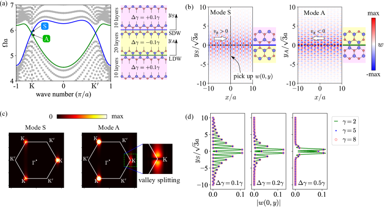
To investigate the edge states, we consider a supercell made of 20 unit cells with negative perturbation sandwiched in between 10 units with positive perturbation on each side, while the average mass is set to . A schematic view of the supercell, together with the band structure along direction are shown in Fig.2 (a). Clearly, there are two types of zigzag domain walls, one is constructed with two small neighboring masses (termed as "SDW") and the other one features two large ones ("LDW"). The projected band diagram, which can be obtained by applying periodic boundary conditions on the left/right and top/bottom edge pairs, unambiguously shows that there are two branches of edge states located in the reopened bulk band gap range (blue and green bands in Fig.2(a)). In Fig.2 (b) we plot the eigenmodes at (valley ) of the two branches, both of which the displacements are confined near the topological domain walls, and decay rapidly as the distances from the domain walls increase.
One may ask which factor(s) dominates the displacement decay into the bulk. To answer this question, we systematically calculate the projected band structures and the eigenmodes for various combinations of the structural parameters . Then the displacement magnitudes along a perpendicular direction of the domain wall are extracted and displayed in Fig.2(d), taking the blue branch band as an example. We consider three values of the average mass (), and for each of them we introduce three levels of perturbation (). The nine corresponding curves are arranged in such a way that the results of different average masses but with the same perturbation level are grouped together and are plotted in the same subfigure for better comparison. As we can see, in each panel, the three curves (solid green line, blue dots and red circles) almost coincide with each other. It indicates that for a fixed perturbation level, the influence of the values of can be nearly neglected. Then by comparing the decay depths between different panels, it can be seen that the larger the perturbation level is, the more localized the topological mode will be. Our analysis reveals that the decay depth is not solely determined by or individually, but by the ratio .
Besides the locally confinement of the displacement distributions, another interesting and important feature of these two edge states, is the symmetry of the mode shape. As displayed in Fig.2(b), the eigenmode localized at the SDW is symmetric about the domain wall, and therefore is labeled as mode S, while the other one is antisymmetric (mode A) about the domain wall. In order to get a better understanding on these two eigenmodes, spatial Fourier transformations are performed. The result in Fig.2(c) shows that there are three highlighted peaks at points in the IBZ for mode S. However, for mode A, the peak near the horizontal , i.e., is not exactly at that point, but is splitted into two weaker out-of-phase peaks with a small shift along direction. The peak splitting can be ascribed to the antisymmetry nature of mode A, which forces the vanishing of the peak at horizontal , because it represents a symmetric plane wave component about the domain wall. This suggests that mode A can operate as a splitter when the wave leaves the PnC through an armchair outlet edge as will be discussed below.
III.2 Topological refraction through zigzag and armchair interfaces
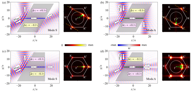
We consider in this section several finite clusters of resonators with different cut edges (zigzag or armchair interfaces) embedded in an infinite HP, forming finite sized topological PnC s, and we study the refraction of the topological valley states upon transmission into the surrounding medium. We use a Gaussian beam with a proper incident angle emitted from the left edge of the PnC to excite the topological valley states. The structural configurations are still chosen to be , and the operating frequency is near the Dirac degenerate point . The corresponding equifrequency contour is shown as dashed circles in the Fourier space. In Fig.3(a)-(d) we plot the MST simulated wave fields and their corresponding Fourier spectra. The Fourier transforms are performed in the region , which simultaneously includes the topological valley states and the refracted waves.
The PnC s in Fig.3(a) and (c) are constructed by positive type lattice above a lattice with negative , forming a SDW which supports symmetric valley modes. For the zigzag interface case displayed in Fig.3(a), the right going waves suggests that we have a positive group velocity, so from the band structure we know that valley-locked states are excited, as confirmed by the three peaks in the Fourier spectrum. The refraction direction can be predicted according to the conservation of tangent components of wave vector parallel to the interface. As can be seen in Fig.3(a)-(d), the predicted refraction angle perfectly matches with the simulated refracted wave. It should be noted that besides a traveling refracted wave emitted into the surrounding medium, there is also a surface wave propagating along the lower half edge corresponding to the component. As for the case of armchair interface in Fig.3(c), we also obtain a good agreement between the equifrequency analysis and the wave field. In this case both and states are excited, which reveals that the armchair interface causes strong reflection of valley modes.
By inverting the top and bottom lattices in Fig.3(a) and (c), we obtain the structures shown in Fig.3(b) and (d), that both feature a topological interface of type LDW and support antisymmetric modes. However, for the antisymmetric branch, the positive group velocity implies we are dealing with the -locked states. In Fig.3(b) the wave vector conservation law leads to a refraction angle different from the case of symmetric mode. Again, perfect agreement with the simulated wave beam is obtained. As for the additional evanescent mode, it propagates along the upper half of the edge, corresponding to the states. Similar to Fig.3(c), the antisymmetric valley mode also encounters strong inter valleys interactions, induced by the reflection at the armchair interface. The outgoing refraction waves are composed of two out-of-phase beams, resulting from the valley splitting mechanism as illustrated in Fig.2(c).
III.3 Influence of decay depth on the refracted waves
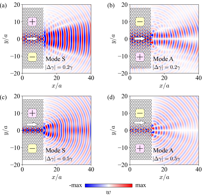
From the comparison between the different panels in Fig.2(d), it can be seen that for a given value of , a larger perturbation ratio results in a shorter decay depth of the topological states. How the variation of the decay depth influences the refracted waves is discussed in this section. Since the Dirac frequency is not altered as is remained fixed, one may naively think that the only effect is the change of the width of the refracted beam. However, as the decay depth decreases, the topological states becomes increasingly localized within a narrow channel. In the extremely short decay depth case, only a few resonators near the topological domain wall are vibrating while the other ones on the outlet edge have almost no displacements. As a result, strong local resonance occurs at the outlet port and the refracted wave is like a field radiated from a point-like source.
To confirm our interpretation, we examine the wave refracted field resulting from different perturbation levels () while keeping fixed. The results for both symmetric and antisymmetric valley modes are displayed in Fig.4. Note that Fig.3(c) and (d) also illustrate the case of for S and A modes, respectively. Let us have a look on the symmetric valley modes, as the perturbation level increases from to . We can see that the excited valley state progressively narrows down, and that the refracted wave gradually changes from a plane wave to a monopole-like radiated field. Similar phenomenon can be found as we vary the perturbation level for the antisymmetric valley state, with the only difference that the refracted wave is a dipole-like source radiated field at large values. In that case it is the result of the out-of-phase vibrations of A valley state on both sides of the domain wall.
III.4 Influence of Dirac frequency on the refracted waves
We have shown in section II that various Dirac frequencies can be achieved by tuning the average mass (see Fig.1(b)). Comparing the equifrequency contour in the HP and the IBZ at a particular Dirac frequency, we find that when
| (27) |
there is one wave vector in the HP whose parallel component along a interface matches with the (or ) locked topological edge states (see the red region in Fig.1(b)). This wave vector normally gives the direction of the refracted wave, as demonstrated in the previous sections. As increases, the equifrequency contour shrinks gradually. One can imagine that the refraction angle will finally converge to , and beyond a certain value of , no such a wave vector can be found (see the blue region in Fig.1(b), ) and therefore only evanescent modes can exists along the interface and no traveling waves will be emitted into the HP.
Now we chose a different structural configuration , as marked by the blue dot in Fig.1(b), which allows us to work at a deeper sub-wavelength scale (Dirac frequency , wavelength ) and prohibits the refraction of a traveling wave into the HP. To have a better understanding of this phenomenon, we calculate the band structures of a suppercell constructed by the PnC and HP, and check the possibility of the existence of surface waves, just as we did for the topological valley states. There are two different types of interface between the PnC and the HP. One is with the small resonators at the very end of the PnC’s cut edge, shown in Fig.5(a) and labeled as "ST", and the other one (termed as "LT") is with the large resonators at the outmost edge, as shown in Fig.5(c). As a reference, the band structure for the pure topological PnC is also presented in Fig.5(d). One can find that the topological states are moved down to around because of the choice of a larger .
For the first supercell structure in Fig.5(a), there are one LDW topological interface and two ST edges. The calculated band structure shows that three edge states emerge in the bulk gap range which includes: one antisymmetric topological valley mode (green dots) localized near the LDW and two degenerate surface modes (namely E1 and E2, marked by red dots) localized near the ST edges. The eigenmodes of these two degenerate states are displayed in Fig.5(b), which clearly shows that the displacement decays rapidly as the measurement point goes away from the edges. There are two points about the evanescent states (E1, E2) that deserve special attention: (1) they have the same group velocity but different mode shapes (being symmetric and antisymmetric about the LDW, respectively), (2) both of the two evanescent modes and the topological A mode at valley are all below the acoustic line. The latter property implies that there is no possibility to find a mode in the HP that can couple with the valley-locked topological states or the evanescent modes.
The band structure analysis corresponding to the LT edge is displayed in Fig.5(c). Only one branch (blue dots) in the bulk gap exists, namely the symmetric topological state localized near SDW. Unlike the aforementioned ST edge, no evanescent modes are found in the gap.
Let us consider now a trapezoid shape PnC constructed by layers of positive perturbed PnC sandwiched in between layers of negative perturbed lattice at both upper and lower sides, as shown in Fig.5(e). In this PnC both SDW (path 1) and LDW (path 3) topological interfaces, and both ST (path 3) and LT (path 4 and 5) types of edges are included. A horizontal Gaussian beam impinges the PnC at the port of path 1, which excites the symmetric valley topological mode. When the wave arrives at the right end of the PnC, it turns into an evanescent wave and propagates along path 2 with a sharp bend, but not along path 4, although the bend is more gentle. When the wave reaches the crossing point of path 3 and 5, instead of keeping going straight along path 5, the wave turns its direction with a sharp bend, and transforms into the antisymmetric valley topological mode along path 3. Finally the topological state refracts into two out-of-phase beams when leaving the PnC at the armchair outlet edge. The above MST simulation of the wave propagation illustrates the efficient coupling between the topological valley states and the evanescent waves whose existence depends on the type of the edge.
IV Examples of functional devices designs
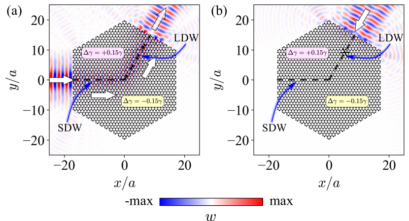
We describe in this section two examples of functional designs of topological devices based on our findings. The first one is a topological elastic diode, which allows transmission of elastic wave along only one direction. It is inspired by the different symmetries of the valley modes localized near SDW and LDW, resulting in the selective excitation (Lu et al., 2017) of these two modes. The structure of this PnC is shown in Fig.6, featuring a topological wave guide formed by two distinct valley phases. The horizontal and then oblique interfaces are of type SDW and LDW and support the symmetric and antisymmetric valley modes, respectively. From the refraction patterns in Fig.3(c) and (d) and considering the reciprocity, we know that a normally incident Gaussian beam can only excite the symmetric mode, but not the antisymmetric one. Our simulations in Fig.6 clearly show the one-way property of this PnC.
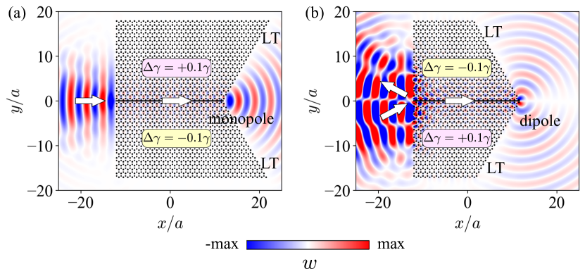
The second interesting application is to construct a topological monopole or dipole emitter. We chose the same structural parameter as in Fig.5, where the working frequency is at deep sub-wavelength scale. We have demonstrated that only evanescent modes can exist at the ST type edge. The two PnC s in Fig.7 are designed to have only LT type edges. Based on our description, neither traveling nor evanescent waves are supported along these edges. As a result, when the topological wave arrives at the very end of our PnC s, the resonators undergo strong local resonances. For the symmetric valley modes traveling along SDW, the in-phase resonance radiates outward a monople field, as shown in Fig.7(a). While for the antisymmetric modes in Fig.7(b), the out-of-phase local resonances act like a dipole source.
V Conclusions
In conclusion, we have proposed an elastic valley PnC by emulating QVHE, achieved simply by tuning the mass perturbation of the resonators. We have shown that a biharmonic equation near the valley points can be mapped into the massive Dirac Hamiltonian by using the method. Moreover, the mass perturbation does indeed contribute to the Dirac mass term, which is responsible for the topological band gap opening. Two different types of domain walls can be built when constructing the valley PnC. Each of them supports a topological symmetric and antisymmetric valley modes, respectively. In contrast with the S mode that refracts into a single wave beam, the A mode refracts into two out-of-phase beams through an armchair outlet edge because of its unique horizontal valley splitting. By parameterize the average mass and the perturbation , the decay depth of these localized modes into the bulk is found to be determined solely by the ratio . Moreover, large mass perturbation would result in strong resonance between scatterers near the domain wall, and may transform the refracted plane wave into a monopole and dipole-like radiated fields, for S and A valley modes respectively. Furthermore, increasing to a large value enables going down to deep sub-wavelength scale, where the topological refracted wave becomes evanescent and can only propagate along a specific type of edge. Finally, we have presented two examples of topological protected functional devices designs, including an elastic diode and a near perfect monople/dipole emitter.
ACKNOWLEDGEMENTS
Linyun Yang acknowledges the research Grant No. 201906120081 provided by the China Scholarship Council (CSC). Ying Wu acknowledges the support from China Postdoctoral Science Foundation (NO. 2020M672615).
References
- Haldane and Raghu (2008) F. D. M. Haldane and S. Raghu, “Possible realization of directional optical waveguides in photonic crystals with broken time-reversal symmetry,” Phys. Rev. Lett. 100, 013904 (2008).
- Lu et al. (2014a) Ling Lu, John D Joannopoulos, and Marin Soljačić, “Topological photonics,” Nat. Photon. 8, 821–829 (2014a).
- Khanikaev et al. (2015) Alexander B Khanikaev, Romain Fleury, S Hossein Mousavi, and Andrea Alu, “Topologically robust sound propagation in an angular-momentum-biased graphene-like resonator lattice,” Nature communications 6, 1–7 (2015).
- Yang et al. (2015) Zhaoju Yang, Fei Gao, Xihang Shi, Xiao Lin, Zhen Gao, Yidong Chong, and Baile Zhang, “Topological acoustics,” Physical review letters 114, 114301 (2015).
- Ding et al. (2019) Yujiang Ding, Yugui Peng, Yifan Zhu, Xudong Fan, Jing Yang, Bin Liang, Xuefeng Zhu, Xiangang Wan, and Jianchun Cheng, “Experimental demonstration of acoustic chern insulators,” Phys. Rev. Lett. 122, 014302 (2019).
- Nash et al. (2015) Lisa M Nash, Dustin Kleckner, Alismari Read, Vincenzo Vitelli, Ari M Turner, and William TM Irvine, “Topological mechanics of gyroscopic metamaterials,” Proceedings of the National Academy of Sciences 112, 14495–14500 (2015).
- Wang et al. (2015) Pai Wang, Ling Lu, and Katia Bertoldi, “Topological phononic crystals with one-way elastic edge waves,” Physical review letters 115, 104302 (2015).
- Mousavi et al. (2015) S Hossein Mousavi, Alexander B Khanikaev, and Zheng Wang, “Topologically protected elastic waves in phononic metamaterials,” Nature communications 6, 1–7 (2015).
- He et al. (2016) Cheng He, Xu Ni, Hao Ge, Xiao-Chen Sun, Yan-Bin Chen, Ming-Hui Lu, Xiao-Ping Liu, and Yan-Feng Chen, “Acoustic topological insulator and robust one-way sound transport,” Nat. Phys. 12, 1124–1129 (2016).
- Mei et al. (2016) Jun Mei, Zeguo Chen, and Ying Wu, “Pseudo-time-reversal symmetry and topological edge states in two-dimensional acoustic crystals,” Sci. Rep. 6 (2016).
- Yves et al. (2017) Simon Yves, Romain Fleury, Fabrice Lemoult, Mathias Fink, and Geoffroy Lerosey, “Topological acoustic polaritons: robust sound manipulation at the subwavelength scale,” New J. Phys. 19, 075003 (2017).
- Miniaci et al. (2018) M. Miniaci, R. K. Pal, B. Morvan, and M. Ruzzene, “Experimental observation of topologically protected helical edge modes in patterned elastic plates,” Phys. Rev. X 8, 031074 (2018).
- Xia et al. (2017) Bai-Zhan Xia, Ting-Ting Liu, Guo-Liang Huang, Hong-Qing Dai, Jun-Rui Jiao, Xian-Guo Zang, De-Jie Yu, Sheng-Jie Zheng, and Jian Liu, “Topological phononic insulator with robust pseudospin-dependent transport,” Phys. Rev. B 96, 094106 (2017).
- Chaunsali et al. (2018) Rajesh Chaunsali, Chun-Wei Chen, and Jinkyu Yang, “Subwavelength and directional control of flexural waves in zone-folding induced topological plates,” Phys. Rev. B 97, 054307 (2018).
- Yu et al. (2018) Si-Yuan Yu, Cheng He, Zhen Wang, Fu-Kang Liu, Xiao-Chen Sun, Zheng Li, Hai-Zhou Lu, Ming-Hui Lu, Xiao-Ping Liu, and Yan-Feng Chen, “Elastic pseudospin transport for integratable topological phononic circuits,” Nature communications 9, 1–8 (2018).
- Yang et al. (2018) Linyun Yang, Kaiping Yu, Ying Wu, Rui Zhao, and Shuaishuai Liu, “Topological spin-hall edge states of flexural wave in perforated metamaterial plates,” Journal of Physics D: Applied Physics 51, 325302 (2018).
- Lu et al. (2017) Jiuyang Lu, Chunyin Qiu, Liping Ye, Xiying Fan, Manzhu Ke, Fan Zhang, and Zhengyou Liu, “Observation of topological valley transport of sound in sonic crystals,” Nature Physics 13, 369–374 (2017).
- Gao et al. (2018) Fei Gao, Haoran Xue, Zhaoju Yang, Kueifu Lai, Yang Yu, Xiao Lin, Yidong Chong, Gennady Shvets, and Baile Zhang, “Topologically protected refraction of robust kink states in valley photonic crystals,” Nature Physics 14, 140–144 (2018).
- Wu et al. (2018) Ying Wu, Rajesh Chaunsali, Hiromi Yasuda, Kaiping Yu, and Jinkyu Yang, “Dial-in topological metamaterials based on bistable stewart platform,” Scientific reports 8, 1–9 (2018).
- Makwana and Craster (2018) Mehul P. Makwana and Richard V. Craster, “Geometrically navigating topological plate modes around gentle and sharp bends,” Phys. Rev. B 98, 184105 (2018).
- Zhu et al. (2019) Zhenxiao Zhu, Xueqin Huang, Jiuyang Lu, Mou Yan, Feng Li, Weiyin Deng, and Zhengyou Liu, “Negative refraction and partition in acoustic valley materials of a square lattice,” Phys. Rev. Applied 12, 024007 (2019).
- Xie et al. (2019) Boyang Xie, Hui Liu, Hua Cheng, Zhengyou Liu, Shuqi Chen, and Jianguo Tian, “Acoustic topological transport and refraction in a kekulé lattice,” Physical Review Applied 11, 044086 (2019).
- Wang et al. (2019a) Wei Wang, Bernard Bonello, Bahram Djafari-Rouhani, and Yan Pennec, “Topological valley, pseudospin, and pseudospin-valley protected edge states in symmetric pillared phononic crystals,” Phys. Rev. B 100, 140101 (2019a).
- Wang et al. (2019b) Wei Wang, Bernard Bonello, Bahram Djafari-Rouhani, and Yan Pennec, “Polarization-dependent and valley-protected Lamb waves in asymmetric pillared phononic crystals,” Journal of Physics D: Applied Physics 52, 505302 (2019b).
- Zhang et al. (2020) Quan Zhang, Yi Chen, Kai Zhang, and Gengkai Hu, “Dirac degeneracy and elastic topological valley modes induced by local resonant states,” Phys. Rev. B 101, 014101 (2020).
- Xiao et al. (2007) Di Xiao, Wang Yao, and Qian Niu, “Valley-contrasting physics in graphene: Magnetic moment and topological transport,” Phys. Rev. Lett. 99, 236809 (2007).
- Wang et al. (2020) Wei Wang, Yabin Jin, Wan Wang, Bernard Bonello, Bahram Djafari-Rouhani, and Romain Fleury, “Robust Fano resonance in a topological mechanical beam,” Phys. Rev. B 101, 024101 (2020).
- He et al. (2018) Hailong He, Chunyin Qiu, Liping Ye, Xiangxi Cai, Xiying Fan, Manzhu Ke, Fan Zhang, and Zhengyou Liu, “Topological negative refraction of surface acoustic waves in a weyl phononic crystal,” Nature 560, 61–64 (2018).
- Zhang et al. (2017) Zhiwang Zhang, Ye Tian, Ying Cheng, Xiaojun Liu, and Johan Christensen, “Experimental verification of acoustic pseudospin multipoles in a symmetry-broken snowflakelike topological insulator,” Phys. Rev. B 96, 241306 (2017).
- Huang et al. (2020) Hongbo Huang, Zhuhua Tan, Shaoyong Huo, Luyang Feng, Jiujiu Chen, and Xu Han, “Topologically protected zero refraction of elastic waves in pseudospin-hall phononic crystals,” Communications Physics 3, 1–8 (2020).
- Lu et al. (2014b) Jiuyang Lu, Chunyin Qiu, Shengjun Xu, Yangtao Ye, Manzhu Ke, and Zhengyou Liu, “Dirac cones in two-dimensional artificial crystals for classical waves,” Phys. Rev. B 89, 134302 (2014b).
- Torrent et al. (2013) Daniel Torrent, Didier Mayou, and José Sánchez-Dehesa, “Elastic analog of graphene: Dirac cones and edge states for flexural waves in thin plates,” Physical Review B 87, 115143 (2013).
- Pal and Ruzzene (2017) Raj Kumar Pal and Massimo Ruzzene, “Edge waves in plates with resonators: an elastic analogue of the quantum valley hall effect,” New Journal of Physics 19, 025001 (2017).
- Mei et al. (2012) Jun Mei, Ying Wu, C. T. Chan, and Zhao-Qing Zhang, “First-principles study of Dirac and Dirac-like cones in phononic and photonic crystals,” Phys. Rev. B 86, 035141 (2012).
- Xiao et al. (2010) Di Xiao, Ming-Che Chang, and Qian Niu, “Berry phase effects on electronic properties,” Rev. Mod. Phys. 82, 1959–2007 (2010).