Dislocation content of grain boundary phase junctions and its relation to grain boundary excess properties
Abstract
We analyze the dislocation content of grain boundary (GB) phase junctions, i.e., line defects separating two different GB phases coexisting on the same GB plane. While regular GB disconnections have been characterized for a variety of interfaces, GB phase junctions formed by GBs with different structures and different numbers of excess atoms have not been previously studied. We apply a general Burgers circuit analysis to calculate the Burgers vectors of junctions in two Cu boundaries previously simulated with molecular dynamics. The Burgers vectors of these junctions cannot be described by the displacement shift complete (DSC) lattice alone. We show that, in general, the normal component of is not equal to the difference in the GB excess volumes, but contains another contribution from the numbers of GB atoms per unit area required to transform one GB phase into another. In the boundaries studied, the latter component dominates and even changes the sign of . We derive expressions for the normal and tangential components of b in terms of the DSC lattice vectors and the non-DSC part due to and additional GB excess properties, including excess volume and shears. These expressions provide a connection between GB phase transformations driven by the GB free energy difference and the motion of GB junctions under applied normal and shear stresses. The proposed analysis quantifies b and therefore makes it possible to calculate the elastic part of the energy of these defects, evaluate their contribution to the nucleation barrier during GB phase transformations, and treat elastic interactions with other defects.
pacs:
64.10.+h, 64.70.K−, 68.35.MdI Introduction
Similarly to bulk materials, interfaces can exist in multiple states, or phases, and exhibit first-order phase transitions.(Cantwell20141, ) Such transitions proceed by nucleation and growth of a new interfacial structure resulting in a discontinuous change in the excess properties of the interface.(Frolov2013, ) For fluid interfacial phases, the conditions of equilibrium and stability were first derived by Gibbs, who called them interfacial states(Gibbs, ) Gibbs showed that an interface should transform to a state with the lowest interfacial free energy. In order to describe such transitions within the existing theories of nucleation and phase transformation, it is necessary to quantify the driving force as well as the nucleation barrier. The interfacial free energy difference provides the driving force according to Gibbs, while the excess free energy associated with the line defect separating the two phases is the penalty for the transformation. A thermodynamic framework quantifying the excess properties of such line defects and their free energy has been recently proposed.(Frolov:2015ab, ) The developed framework is Gibbsian in spirit and makes no assumptions about the atomic details of the defect structure. It assumes that the energy of this defect is finite, scales with its length, and is independent of the system size. As a result, the treatment applies to fluids and some solid systems,(PhysRevB.95.155444, ) but cannot be extended to general solid-solid interfaces without significant approximations.
A grain boundary is a solid-solid interface formed by two misoriented crystals of the same material. The phase behavior of GBs has recently become a topic of increased interest due to the accumulating experimental and modeling evidence of phase transformations at such interfaces.(Divinski2012, ; PhysRevLett.59.2887, ; Cantwell20141, ; krause_review_2019, ; Rickman2016225, ; doi:10.1080/095008399177020, ; Rohrer2016231, ; rupert_role_2016, ; Dillon20076208, ; OBrien2018, ; ABDELJAWAD2017528, ; rajeshwari_k_grain_2020, ; glienke_grain_2020, ) The line defects formed between two different GB phases can have a long range elastic field associated with them. GB disconnections are examples of such line defects and have been analyzed for different types of interfaces.(HIRTH2013749, ; Hirth96, ) Disconnections on GBs and phase boundaries have been investigated by modeling and experiments.(Medlin2017383, ; medlin_accommodation_2003, ; medlin_accommodation_2006, ; Pond03a, ; hirth_disconnections_2016, ; rajabzadeh_role_2014, ; zhu_situ_2019, ) On the other hand, GB phase junctions have received much less attention since there have only been a few studies of GB structures with two different connected interfacial phases. At present, the topological nature of these defects and the magnitude of their Burgers vectors are not well understood. Recent modeling and experimental studies in elemental Cu suggest that the dislocation character of these defects has a strong effect on the kinetics of GB phase transformations and could explain the low transformation rates at room temperature.(meiners_observations_2020, ) The elastic field contribution to the energy could, in principle, dominate the GB phase nucleation behavior, and play a role in the interaction of the junctions with other GB disconnections, lattice dislocations and point defects.
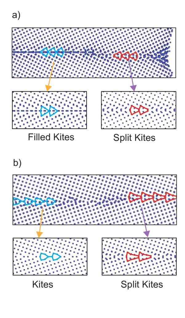
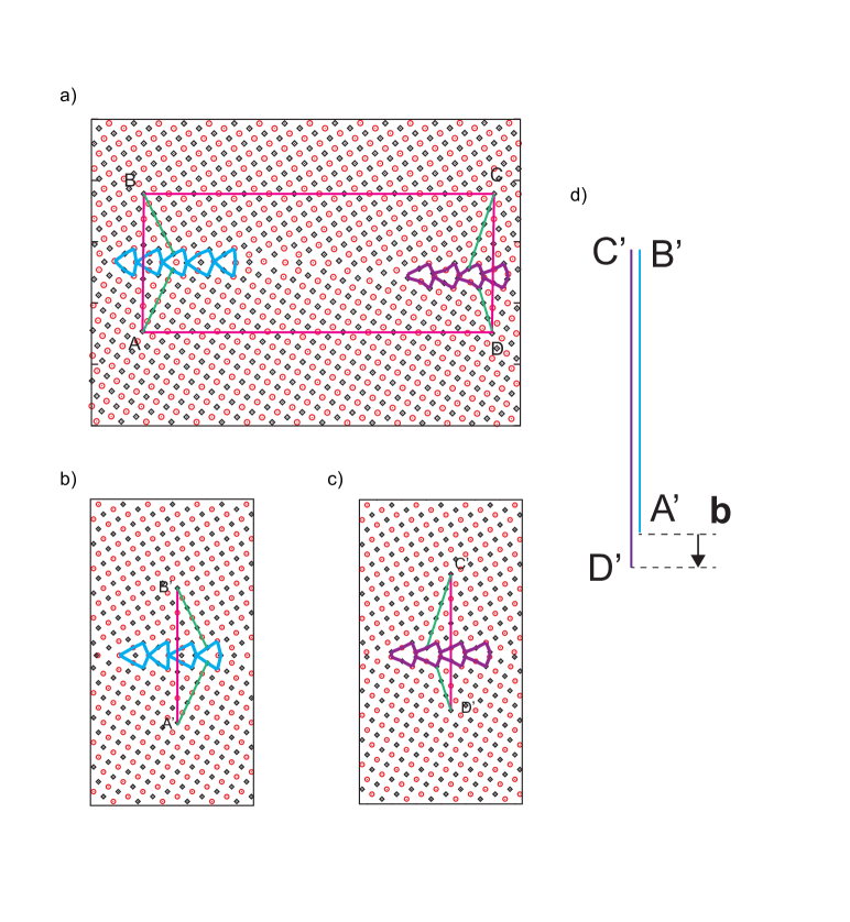
Atomistic simulations have demonstrated first-order transitions in and symmetric tilt GBs in Cu.(Frolov2013, ) The heterogeneous structures of these two GBs, each containing two different phases, are shown in Fig. 1. Both structures were obtained by molecular dynamic simulations at T=800K with the boundary connected to an open surface. In these simulations the surface acts as a nucleation site and a source of extra atoms or vacancies necessary to grow the new GB phase. Because the cores of these GB phases are composed of different number of atoms, atoms must be inserted or removed to transform from one phase to the other.(doi:10.1080/01418618308243118, ; doi:10.1080/01418618608242811, ; DUFFY84a, ; Phillpot1992, ; Phillpot1994, ; Alfthan06, ; Alfthan07, ; Chua:2010uq, ; Frolov2013, ; Demkowicz2015, ) During the transformation these GB phases are separated by a GB phase junction. The line direction of this defect is normal to the plane of the image and it spans the periodic dimension of the simulation block. The transformation was accompanied by the migration of the GB phase junction, which required diffusion of extra atoms from the surface. These two boundaries provide a convenient model system to analyze the topological character of GB phase junctions and quantify their Burgers vectors. In this work, we show that GB phase junctions have a dislocation character, just like regular disconnections, but their Burgers vectors differ from crystallographic DSC vectors since they include a contribution resulting from the difference in the GB structures. We demonstrate a general Burgers circuit analysis that quantifies the dislocation content of these defects. We interpret it in terms of contributions from different excess properties, including excess volume and shear, and the difference in the number of atoms required to transform one GB phase into another.
II Methodology
II.1 Closure failure and Burgers circuit construction
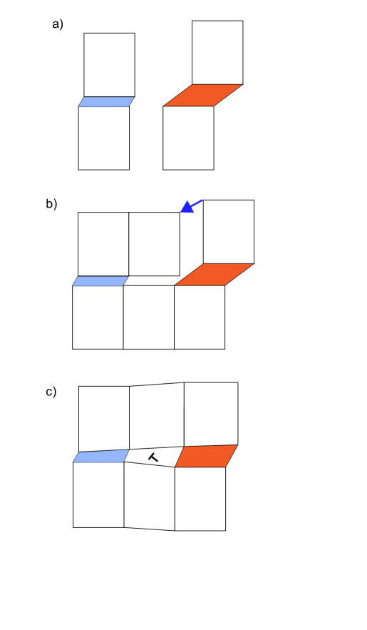
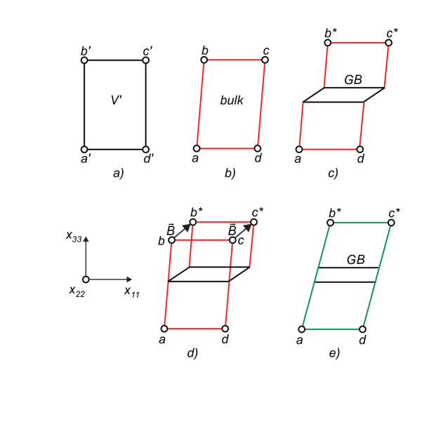
Fig. 2 shows why GB phase junctions are expected to have dislocation character and generate long-range elastic fields. Consider two bicrystals with different GB structures or phases, as shown schematically in Fig. 2a. Each GB structure has its own excess properties such as excess volume(Gibbs, ; Cahn79, ) and shear.(Frolov2012a, ; Frolov2012b, ) In addition, the GB cores are composed of a different number of atoms. As a result the two bicrystals are geometrically incompatible. To form a GB phase junction we need to join the two bicrystals. Fig. 2b shows that this procedure will result in a closure failure. In order to form the junction using the Volterra operation,(Hirth, ) we elastically strain both bicrystals by appropriate amounts, so that their bulk lattice planes away from the boundary match. As a result of this procedure, we form a line defect with a dislocation character, as shown in Fig. 2c.
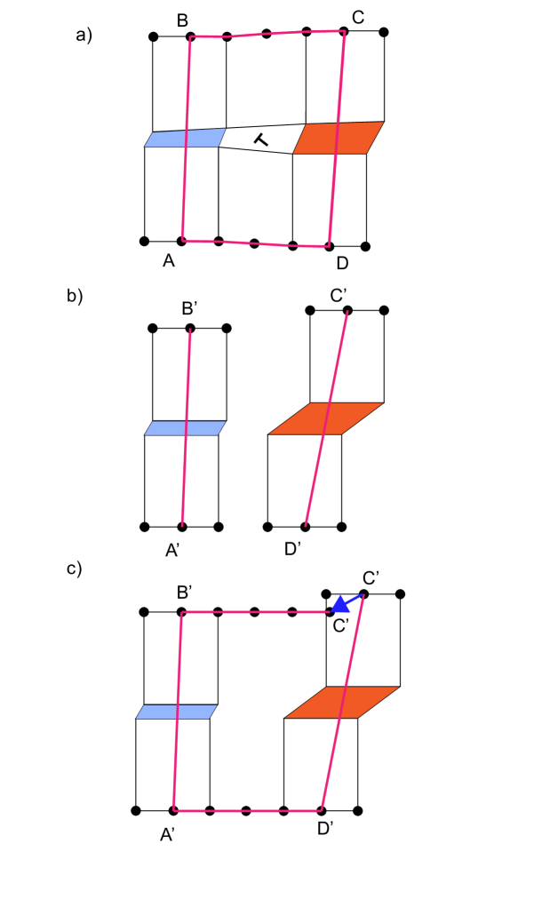
Based on how the GB phase junction was created in this thought experiment, it is straightforward to design a Burgers circuit that would quantify the closure failure, i.e., the Burgers vector of the defect. We start with the deformed bicrystal shown in Fig. 3 and construct a closed circuit ABCD around the GB phase junction. The corner lattice points of the circuit coincide with the lattice sites located inside the bulk crystal, far away from the GB junction and GB phases. Two vectors and cross the two different GB phases, while the other two vectors and are located inside the bulk of the two grains and are lattice vectors. To calculate the Burgers vector of the GB phase junction we measure these vectors in the reference state before the junction was created. The vectors and are lattice vectors and their components can be expressed in terms of the reference bulk lattice parameter. The crossing vectors should be mapped on the respective reference bicrystals as shown in Fig. 3b. Here, the references for the crossing vectors are chosen as bicrystals possessing only a single GB phase so that the crossing vectors will be unaffected by the elastic field of the GB phase junction. With such a reference, it is always possible to find a pair of of crystallographically equivalent lattice sites, such as A’ and B’ and thereby measure the vector . Alternatively these equivalent lattice sites can be selected in the same deformed bicrystal but infinitely far away from the junction. The points A, B, C and D can be chosen arbitrary as long as they enclose the phase junction and their positions in the reference state are not affected by the GB. In other words, the difference between any two choices of a given lattice point such as equals a perfect lattice vector, which also means that the difference between any two choices of the crossing vectors is a DSC vector. According to the circuit construction, the closure failure, or the Burgers vector , equals the sum of the four vectors measured in the undeformed state:
| (1) |
Here, we follow start to finish right handed (SFRH) convention. In Section III, we apply this approach to quantify the dislocation content of GB phase junctions in the and Cu GBs. We describe how to calculate the crossing vectors and in the reference bicrystals.
II.2 Relating normal and tangential components of the Burgers vector to excess properties of GBs and DSC lattice vectors.
Equation (1) and the circuit procedure described in Sec. (II.1) are sufficient to calculate the Burgers vector of any given GB phase junction.111In atomistic simulations this is always possible at least in principle. The reference GB phases can be generated separately or carved out from the deformed state and relaxed in a proper way so that the reference crossing vectors could be calculated. In experiment, the analysis cannot be completed based on a single image of the deformed state. However, GB structures sufficiently far away from the junction can be approximated as reference states. In general, a full three-dimensional structure is necessary to determine all three components of . The procedure, however, does not quantify the specific contributions to from bicrystallography and from the difference in the GB excess properties. In this section, we express the crossing vectors in terms of crystallographic properties and GB excess properties and quantify their contributions to the Burgers vector. Relative normal and tangential displacements of the grains due to the GB can be described using the deformation gradient formalism.(Frolov2012a, ; Frolov2012b, ) The proposed thermodynamic framework enables quantification of the excess shear at GBs and its relation to the relative translation of the grains. Both the normal and tangential components of the crossing vectors can be derived within this approach and related to the excess volumes and shears of different GB phases. In the following two subsections we will first derive the normal Burgers vector component using the well-known definition of the GB excess volume. In the next section, we derive all three components of using the deformation gradient approach proposed in Refs.(Frolov2012a, ; Frolov2012b, ).
II.2.1 Normal component
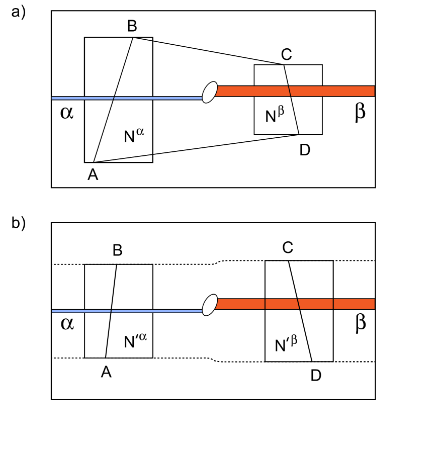
The normal components of the crossing vectors measured in the reference state can be expressed as a sum of bulk and GB contributions using the familiar definition of the GB excess volume. The GB excess volume is equal to the difference between the volume of the bicrystal spanned by the crossing vector and containing atoms, and the volume of the bulk crystal containing the same number of atoms divided by the GB area. The regions spanned by the crossing vectors are shown in Fig. 4a. For two GB phases and we have
| (2) |
| (3) |
where is volume per atom in the perfect lattice, is the GB area and the superscripts refer to bicrystals with GB phases and . Eqs. (2) and (3) express the normal components of the crossing vectors in the reference state in terms of the excess volumes and numbers of atoms per unit area:
| (4) |
| (5) |
Here, both the GB excess volume and the second terms on the right-hand side, , have the units of length. To illustrate the physical meaning of the second term, consider first a region inside a perfect crystal. In this case, equals the distance between the corresponding atomic planes, which is a normal component of a lattice vector. On a DSC lattice formed by two perfect crystals with different orientations, this quantity is equal to the normal component of a DSC vector. However, for a general bicrystal with a GB, is not necessarily a component of a DSC vector because the number of atoms at the GB is not restricted to be the same as in the lattice. We can now combine Eqs (4) and (5) with Eq. (1) to derive an expression for :
| (6) |
Equation (6) is an analytical expression for the normal component of the Burgers vector of a GB phase junction. The equation reveals the different factors that contribute to . The first one is the difference between the excess volumes of the two GB phases. The second term corresponds to the difference in the number of atoms inside the two regions spanned by the crossing vectors. Finally, the two lattice vectors of the upper and lower grains contribute the DSC component .
We derived Eq. (6) for one particular GB phase junction, but we can use this analysis to demonstrate that all other possible Burgers vectors of such junctions form a DSC lattice. In addition, according to Eq. (6) the origin of this lattice is shifted away from zero in the direction normal to the GB plane by . To do so, we consider all other possible junctions between the same GB phases with different Burgers vectors and construct the Burgers circuits for each junction such that the crossing vectors and are the same for all junctions and and may not be the same. Then the difference between any two Burgers vectors will be equal to the difference in of the two circuits, which is necessarily a DSC vector since and are lattice vectors of different grains. As a result the Burgers vectors of any two junctions differ exactly by some DSC vector and all admissible Burgers vectors form a DSC lattice.
So far we assumed that the corners of the circuit were chosen in a general way, as shown in Fig. 4a. We can now consider some particular choices of the lattice sites A, B, C and D to relate the terms in Eq. (6) to some measurable properties of GB junctions. Specifically, consider a circuit shown in Fig. 4b when the lattice vectors and are located along atomic planes parallel to the GB plane. These atomic planes are elastically distorted due to the presence of the dislocation, but they are parallel to each other and to the GB plane in the reference state. By this choice, setting the DSC term in Eq. (6) to zero and we obtain
| (7) |
Here, we define as the defect absorption capacity of a GB junction. It is equal to the difference in the number atoms inside the equivalent volumes located on the two sides of the junction and bound by the same atomic planes parallel to the GB plane shown in Fig. 4b. The defect absorption capacity represents the number of atoms per unit of the GB area absorbed or ejected when the junction moves along the GB.
As a simple illustration, consider the climb of a regular disconnection inside a single-phase GB. The motion of this disconnection requires a supply of atoms or vacancies with the number of the point defects proportional to the normal component of the Burgers vector, which in this case is a DSC lattice vector.(HIRTH2013749, ; Hirth96, ) According to Eq. (7) the defect absorption capacity of such a disconnection is given by , since the GB structure on the two sides of the disconnection is the same and . This example also illustrates that different disconnections may have different defect absorption capacities and the difference is given by a normal component of some DSC vector divided by the volume per atom. For a general GB phase junction separating different GB phases, however, the defect absorption capacity is not defined by the DSC lattice alone, as will be discussed below.
For a given physical system, of a GB phase junction is a well defined, single-valued quantity. However, any GB phase junction can in principle increase or decrease its dislocation content and its defect absorption capacity by absorbing or ejecting regular disconnections. This multiplicity of possible is captured by the second term in Eq. (7). While the first term, , is a constant set by the values of the excess volumes of the two GB phases, the second term, , represents a set of possible values. When disconnections are ejected or absorbed by the junction, term describes the discrete changes in the normal component of the Burgers vector which occurs in increments dictated by the DSC lattice. For this reason, it makes sense to further split in Eq. (7) into contributions described by the DSC lattice and the smallest in magnitude non-DSC part :
| (9) |
Equation (8) demonstrates that all admissible Burgers vectors of GB phase junctions can be obtained by constructing a DSC lattice for a given bicrystal and shifting the origin of this lattice by a non-DSC vector with the normal component given by . The in-plane components of this shift vector will be derived in the next section. Eq. (9) shows that the defect absorption capacity of a junction can change in increments dictated by the DSC lattice, but may not be reduced to zero in some cases because of . As introduced by Eq (8), is smaller than the smallest normal component of a DSC vector . It is also defined up to the and can be both positive and negative.
To illustrate the meaning of the different terms in Eqs. (8) and (9) we consider several examples. We start again with a regular disconnection as a simplest case when the GB structure is the same on both sides of the line defect. The Burgers vector is exactly a DSC lattice vector, as a result . In other words, the defect adsorption capacity of a regular disconnection is described exactly by the normal components of the DSC lattice vectors.
In another special case, consider a junction formed by two different GB phases composed of the same number of atoms, meaning that given a bicrystal with one GB phase, the same bicrystal with a different GB phase can be obtained by rearranging the atoms in the GB region and changing the relative translations of the grains if necessary without inserting or removing atoms from the GB core. In this case again, but the excess GB volume difference contributes to the non-DSC part of the Burgers vector normal component: . As a result, differently from regular disconnections, the origin of the DSC lattice of all possible Burgers vectors of such a junction is not located at zero. In a general case, however, term is not equal to a normal component of a DSC vector or zero and is not zero.
At this point was derived through its contribution to the normal shift of the origin of the DSC lattice of all possible Burgers vectors of a given GB phase junction. We now turn our discussion to the physical meaning of this quantity. We show that corresponds to the smallest number of atoms or vacancies per unit area required to transform one GB phase into another. Indeed, out of all possible choices, we can always select a junction such that the difference is smaller than the smallest normal component of any DSC vector, making in Eq (8) zero and . For this junction, by definition, is the difference in the number of atoms inside two regions containing two different GB phases and can be interpreted as the number of atoms required to be inserted or removed to transform one GB phase into another. This number is also the smallest, because any other changes in the number of atoms that preserve the two given GB structures require insertion or removal of atoms in the increments of atoms per unit area.
A growing number of modeling studies demonstrated that for many GB transitions is not zero, some number of atoms must be added or removed to transform one GB phase to the other. The difference in the number of GB atoms originates from the fact that some GB structures cannot be obtained by simply joining two perfect half crystals: in addition, some fraction of the GB atoms needs to be added or removed from the GB core and this fraction is different for different GB phases. The importance of optimizing the number of atoms at GBs has been demonstrated in different GB types and several different materials systems.(doi:10.1080/01418618308243118, ; doi:10.1080/01418618608242811, ; DUFFY84a, ; Phillpot1992, ; Phillpot1994, ; Alfthan06, ; Alfthan07, ; Chua:2010uq, ; Frolov2013, ; Demkowicz2015, ; Han:2016aa, ) New computational methods designed to perform grand-canonical optimization of GB structure have been proposed.(Zhu2018, ; banadaki_efficient_2018, ; gao_interface_2019, ; yang_grain_2020, )
The optimization of the number of atoms in the GB core is related to the atomic density at the boundary, but it is not uniquely determined by the excess GB volume and represents an additional GB parameter. Previous studies reported the actual number of removed or inserted atoms for a given GB cross-section or calculated it per unit area relative to an idealized reference bicrystal system which is arbitrary.(Alfthan06, ; Demkowicz2015, ; Han:2016aa, ) In our previous study, we reported a fraction of GB atoms calculated relative to the numbers of atoms in a bulk plane parallel to the boundary.(Frolov2013, ) To calculate this quantity for a given GB, we count the total number of atoms inside a region containing a GB and the number of atoms in one atomic plane parallel to the GB located inside the perfect crystal. The fraction was then calculated as a modulo of this two numbers and was divided by the number of atoms in one plane. The advantage of the quantity introduced in Ref. (Frolov2013, ) is that it allows to calculate a well defined property related to the numbers of atoms at GBs without keeping track of the number of atoms inserted or removed during the process of GB optimization. While this parameter can be readily calculated for twist and symmetric tilt boundaries for some crystal lattices, it cannot be accepted as a general descriptor. For example, this quantity cannot be calculated for asymmetric boundaries with different areal number density of atoms per plane in the different grains. Moreover, even for symmetric boundaries this descriptor needs to be generalized to work for crystal lattices with more than one atom per primitive unit cell, such as in diamond or hexagonal close packed (hcp) lattices. Note that for symmetric tilt GBs the number of atoms per unit area in one bulk plane is given by . As a result, for such boundaries the proposed fraction of atoms is exactly equivalent to subtracting out the largest DSC component and from the normal component of a crossing vector of a given boundary and dividing it by , which is analogous to Eq. (9) derived for . As a modulo, is required to be positive. The advantage of calculating the smallest non-DSC component of a crossing vector derived in this study instead of is that it is aslo defined for asymmetric GBs. This non-DSC component can be calculated for each individual boundary and is related to the excess number of GB atoms per unit area which we denote as relative to the bulk system defined by the subtracted DSC vector component. By this definition, this number of GB atoms per unit area is defined up to and can be positive and negative.
In the context of GB phase transformations analyzed in this work, , representing the smallest number of atoms or vacancies per unit of GB area required to transform one GB phase into another, is a well defined quantity which can be measured for symmetric and asymmetric GBs. The derived Eq. (8) relates to the non-DSC part of the normal Burgers vector component of the GB phase junction. In our derivation leading to Eq. (8), we made no assumptions about the type of the CSL boundary and it is valid for both symmetric and asymmetric boundaries. We analyze specific examples of GB phase junctions and calculate in the atomistic simulation section of this article.
II.2.2 Deformation gradient treatment of all three components of the Burgers vector
In the previous section we showed that the normal components of all possible Burgers vectors of a GB phase junction can be described by a DSC lattice with the origin shifted normal to the GB plane by a vector related to the difference in the excess volumes and the number of atoms . Since a GB phase junction is a dislocation, it will experience a Peach-Koehler (PK) force when mechanical stresses are applied.(Hirth, ) This force produces a driving force for the junction motion i.e., GB phase transformation, and will also influence the equilibrium coexistence. When tension or compression is applied normal to the GB plane, the driving force or the work of the PK force per unit area is equal to the product of the normal component of stress and the normal component of the Burgers vector.
Another way to describe the same effects is to consider the free energies of the two phases. Consider a junction between two GB phases with . The mechanical stresses normal to the GB plane change the free energies of both grain boundary phases, with the change proportional to the excess volume of each boundary, as described by the absorption equation (Gibbs, ). This part of the free energy difference due to the normal stress contributes to the driving force for the GB phase transformation and is given by the product of the normal component of stress and the difference in the excess volumes. So far, we have demonstrated that the normal component of the Burgers vector contains a contribution from the difference in the excess volumes. Thus, the analysis presented here for the normal component of provides a connection between these two equivalent descriptions of the driving force.
In addition to the normal stress, solid interfaces support shear stresses parallel to the interface plane.(Robin74, ; dingreville_interfacial_2008, ; Larche_Cahn_78, ; doi:10.1063/1.448644, ) These stresses also result in a PK force on GB phase junction and change the free energies of the two phases. Excess shear of an interface is an extensive property that describes how the interface free energy changes with applied shear stress parallel to the boundary.(Frolov2012a, ) Excess shears and GB free energy as a function of shear stress have been calculated for different GBs using atomistic simulations.(Frolov2012b, ; meiners_observations_2020, ) A recent study demonstrated a shear stress induced GB transformations as well as equilibrium coexistence under applied shear stress. Moreover, the coexistence stress was accurately predicted from the values of the excess shears and the stress dependence of the GB free energies.(meiners_observations_2020, )
In this section we derive an expression for all three components of , including the tangential components. We show that the origin of this DSC lattice of possible Burgers vectors is also shifted in the plane of the boundary due to the difference in excess shears. To do so, we need to express all three components of the crossing vectors in terms of contributions from the bulk and GB properties, such as the GB excess volume, shear and the number of atoms. Following Ref. (Frolov2012a, ; Frolov2012b, ), we assumed that there exists a mapping of one grain into the other, which establishes a unique relation between the lattice sites of the two crystals. This transformation is described by a deformation gradient . In this work, we only consider mappings that exclude transformations resulting in GB coupled motion, which means that components of the deformation gradient are the same for both grains, where the superscript b indicated the bulk part of the crystals. Specific examples of excess shear calculations for different GBs can be found in Refs. (Frolov2012b, ; meiners_observations_2020, ).
The two-dimensional schematic in Fig. 5 shows how the deformation gradient can be used to describe the mapping between a single crystal and a bicrystal with a GB phase. Here we present equations for one phase () and subsequently distinguish GB phase specific properties by respective super-scripts. We assume that there are lattice sites, or markers, that can be selected and tracked during an imaginary transformation of a single crystal in Fig. 5b into a bicrystal shown in Fig. 5c. These lattice sites, labeled as a, b, c and d define a parallelogram (parallelepiped in three dimensions) which has different shapes for the sites located in the single crystal and the bicrystal. These shapes, shown in Figs 5b and e, can be described using deformation gradients and that map a common mathematical reference state shown in Fig. 5a on both parallelograms. This mathematical reference state is used to calculate the deformation gradients only and should not be confused with the reference state for the Burgers circuit analysis discussed earlier. Notice that, to describe the transformation from Fig. 5 b to c, we use an effective deformation gradient which is calculated based on the positions of the lattice sites as shown in Fig. 5 e. For three-dimensional systems, these deformation gradients are given by(Frolov2012a, ; Frolov2012b, )
| (10) |
where vector shown in Fig. 5 d describes the change in the position of the site b relative to its position in the single crystal. The coordinate axes are indicated in the figure. From the formal definition of by Eq. (10) and Figs 5c and e, it is clear that its components depend on the size of the selected GB region and approach bulk values when the GB area to volume ratio decreases. We now recognize that is a crossing vector and its components can be expressed by =, where . There are three excess properties associated with vector : two GB excess shears and and one GB excess volume , which can be found from the relation(Frolov2012a, ; Frolov2012b, )
| (11) |
where as before N refers to the total number of atoms inside the region spanned by the crossing vector and is the number of atoms in the volume of single crystal defined by lattice sites , , , and . For , Eq. (11) recovers the well known expression for excess GB volume . Eq. (11) relates the three components of the crossing vector to the excess properties of the GB.
We can now apply this equation to GB phases and separately and evaluate the crossing vectors and in the Burgers circuit analysis:
| (12) |
| (13) |
Notice that the bulk deformation gradients and are not identical, as they depend on how the lattice sites and were chosen. It is possible to choose the same bulk reference state for both GB phases and use the and maps to predict the locations of the sites and . In this case, the A and D corners of the Burgers circuit can still be selected arbitrarily, but their counterparts in the upper grain are determined by the deformation gradient and the number of atoms in the reference bulk crystal or . Without loss of generality we assume that the lattice sites in both bicrystals are chosen such that they are related by the same . Then, subtracting Eqs. (12) and (13) we obtain the following expression for the Burgers vector
| (14) |
where, as before, corresponds to the difference in the number of atoms in bicrystals spanned by the crossing vectors, and the DSC vector appears as a result of adding the lattice vectors and . Eq. (14) shows that all possible Burgers vectors form a DSC lattice with the origin shifted by a vector , which components contain excess volume, excess shears and a term related to the difference in the number of atoms. We can further reduce the second term in Eq. (14) to by subtracting out all DSC vectors, which is equivalent to selecting one of the Burgers vectors closest to the origin of the shifted DSC lattice, and obtain :
| (15) |
Eq. (15) is a vector form of Eq. (8) derived previously for only one component . The first term in Eq. (15) represents the contribution to the Burgers vector from the difference in excess volumes and excess shears, while the second is related to the the number of atoms required to transform one GB phase into another. These two terms containing properties specific to the two GB phases represent the non-DSC vector by which the origin of the DSC lattice of all possible Burgers vectors of the junction is shifted relative to zero.
As discussed previously,(Frolov2012a, ; Frolov2012b, ) the excess shear as an equilibrium property is not defined for GBs that move under applied shear stress. As an example, consider symmetric tilt GBs. When such a GB moves, one grain transforms into the other with a different shape. Thus the deformation gradients in the two grains are not the same. When such a boundary does not move, can be assumed to be the same in both grains and a relation between lattice sites across the GB has to be established to calculate the formal . One way to establish this relation is by following the bulk lattice sites during the GB creation procedure such as the -surface approach. For example, Pond and Vitek used this approach to track relative displacements of the grains and calculated the Burgers vectors of partial GB dislocations formed by identical GB structures corresponding to different grain translation vectors.(pond_periodic_1977_1, ; pond_periodic_1977_2, ) While this procedure is straightforward if the boundary structures can be obtained simply by translating and relaxing the adjacent crystals, it cannot be applied if the adjacent GB phases are composed of different numbers of atoms.
On the other hand, even for boundaries that move by coupled motion, such as symmetric tilt boundaries, it is straightforward to calculate the excess shear component parallel to the tilt axis and use Eq. (15) to predict along that direction. A recent experimental and modeling study demonstrated phases of [111] symmetric and asymmetric tilt GBs in Cu that had different translations along the tilt axis. According to Eq. (15), GB phase junctions of these boundaries have a screw component along the [111] tilt axis. GBs with significant grain translations along the tilt axis have been previously reported(doi:10.1080/01418610208240038, ; PhysRevLett.70.449, ) for other boundaries. The translations are typically on the order of a half of the inter-planar distance. These translations result in large excess shears and produce junctions that have a large screw component parallel with the tilt axes, such as the one studied in Ref. (meiners_observations_2020, ). Quantification of these Burgers vectors using the described Burgers circuit analysis and Eq. (14) allows one to make predictions about the stability of metastable states and explain the slow kinetics of GB phase transformations observed in Ref. (meiners_observations_2020, ).
III Burgers vectors of GB phase junctions in symmetrical tilt Cu boundaries
We now apply the methodology described above to analyze two specific GB phase junctions in the and Cu boundaries(Frolov2013, ) shown in Fig. 1. First, we calculate the vectors using the Burgers circuit construction described in Sec. II.1. Then we predict using Eqs (8) and (14) with the GB excess properties summarized in Table 1, and compare the values of obtained by the two methods.
III.1 Analysis of the GB
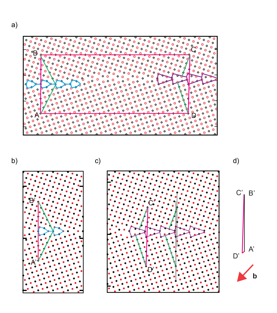
Figure 6a shows a closed circuit ABCD around the GB phase junction in the GB. For convenience, we consider a slice parallel to the tilt axis containing only two atomic planes. The atoms with different coordinates normal to the page are colored in red and black. Vectors and cross the Kite and Split Kite GB structures, respectively. To simplify the analysis, we have chosen the lattice sites A, B, C and D such that the vectors and have the same length equal to in the reference state, where Å is the fcc lattice constant.(Mishin01, ) Since the two vectors have the same magnitude and opposite signs, they cancel each other in Eq. (1) and do not contribute to . The reference bicrystals are shown in Fig. 6b and c. For these two simulation blocks, the boundary conditions are periodic in the boundary plane and the stresses inside the bulk crystals away from the boundary are zero. The exact simulation procedure is not important as long as the structures of the boundaries match the ones in the two GB phase state. In reality, the structures generated at 0 K and those taken out from the simulation at T=800K were not identical. The high temperature structures contain point defects and may have a somewhat different arrangement of the atoms. Nevertheless, the 0 K and finite temperature structures are very close. Table 1 summarizes the properties of the different GB phases calculated at 0 K.(Frolov2013, ) In this work, we used both the 0 K and the finite temperature structures to generate the reference bicrystals and obtained the same result within the expected error of the calculation method.
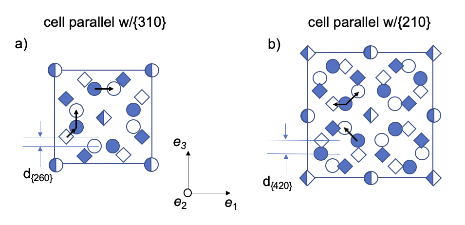
To map the crossing vectors and in the deformed state on the vectors and in the reference state, we follow the lattice planes in both crystals as indicated by the green lines shown in Fig. 6. The exact choice of the guiding lines is not important as long as they help to establish the relation between the lattice points A and B on different sides of the GB. Performing a direct calculation of the components of the crossing vectors in the reference state, we obtained for the two bicrystals Å, Å and Å, Å. The non-zero shown in Fig. 6c indicates that in the Split Kite structure the upper crystal is translated to the right relative to the bottom crystal by the amount of . At the same time, the Kite structure is symmetric with . We can express the normal components of the crossing vectors in terms of the bicrystal and GB contributions. and , where and represents the shortest distance between two atomic planes in the crystal parallel to the GB plane. The smallest DSC vector normal to the GB plane has the length , as shown in Fig. 7a, as a result even for simple Kite structure ( is the unit vector normal to the GB plane) is not a DSC vector, which is not surprising because GBs allow for grain translations parallel to the GB plane. The non-DSC part of the crossing vector equals to reflects that translation and can be used as a useful GB descriptor. While all crossing vectors form a DSC lattice, the origin of this lattice is also shifted normal to the GB plane by . Notice that for this boundary is equal to an integer number times the smallest normal component of DSC equal to . The Split Kite structure cannot be obtained by joining two perfect half crystals and requires an insertion or removal of a fraction of atoms less than one atomic plane. This is reflected by the terms in the expression for .
Summing up the measured vectors of the circuit using Eq. (1) we obtain the components of the Burgers vector of the GB phase junction: Å, Å. Since the entire circuit was located in one plane and there were no grain translations parallel to the tilt axis, Å. The negative value of indicates that the bicrystal with the Split Kite structure is effectively thicker than the bicrystal with the Kite structure. This result may seem counterintuitive since the Split Kite has a smaller excess volume then the Kite phase according to Table 1. To explain this result, we express the calculated Burgers vector in terms of DSC vectors and the excess GB properties.
We now apply Eq. (6) to predict the Burgers vector for the junction in the GB. The excess volumes and the numbers of atoms in the two GB phases, Kites and Split Kites, can be found in Table 1. TheGB areal number density is expressed as a fraction of the number of atoms in one lattice plane parallel to the GB. The excess volume of the Split Kite phase is smaller than that of the Kites, as a result is positive, while Å is negative. Summing up these two contributions we obtain a negative value , indicating that the bicrystal with Split Kite structure is indeed effectively thicker than the bicrystal with the Kite structure. The value of calculated using Eq. (6) also matches the value obtained above using the Burgers circuit construction within the numerical accuracy. This agreement suggests that the dislocation content of this particular GB phase junction originates entirely from the difference in excess properties of the two GB structures i.e., from the difference in their excess volumes and the numbers of atoms. Indeed, the number-of-atoms term Å is well defined: during the transformation this exact amount of atoms per unit of area diffused from the open surface and transformed the initial Kite phase to the Split Kite phase, as was confirmed in Ref. (Frolov2013, ). This change in the number of atoms can be easily evaluated by counting the total number of atoms inside two regions on the two sides of the GB phase junction, containing the two different GB phases with the same area. Such a calculation was performed in the original study.(Frolov2013, ) In other simulations similar junctions were formed by inserting a controlled number of atoms into the preexisting parent phase.
The parallel component of the disconnection arises from the relative shift of the grains parallel to the GB plane, which is different in the two structures. For the given junction this difference is equal to a DSC vector Å. Note that is smaller than the shortest DSC vector with the same direction, with has the length . In general, the parallel relative shift for a GB structure is not constrained to be a DSC vector. The parallel components of the crossing vectors can be expressed as a sum of DSC vector components and the excess shears at the boundary as described by Eqs. 14. As was discussed above, symmetric tilt boundaries move under shear in that particular direction and excess shear becomes ill-defined. For a stationary boundary, this component of the Burgers vector can be formally interpreted to have a contribution from the differences in the excess shears and the numbers of atoms of the two GB phases as described by Eq. (15).
A GB phase junction can change its dislocation content by absorbing or ejecting GB disconnections with Burgers vectors given by vectors of the DSC lattice. We can consider such reactions and compare the Burgers vector of the GB phase junction obtained in MD to other possible valid vectors. The current Burgers vector in the coordinate frame of the interface simulation is given by , while the primitive DSC lattice vectors are , and , . Fig. 7a shows the dichromatic pattern constructed for this bicrystal as well as the primitive DSC lattice vectors.(doi:10.1098/rsta.1979.0069, ; pond_bicrystallography_1983, ) It is clear, that all possible disconnection reactions leave the magnitude of the current Burgers vector at best unchanged. For example, consider an absorption of , which can glide in the boundary. This dislocation reaction changes the direction of the GB phase junction Burgers vector to , but not its magnitude. Other disconnection reactions increase the magnitude of the Burgers vector and we conclude, that this junction formed when the Split Kite structure absorbed extra atoms gives the smallest Burgers vector possible for this GB.
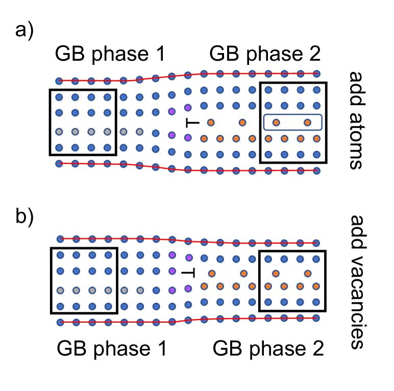
The analysis of other possible Burgers vectors can be used to explain why the GB transformation in our simulation proceeded by absorption of extra atoms and not vacancies. We can also predict possible Burgers vectors for vacancy induced transformations. In the absence of mechanical stresses, the primary driving force for the GB phase transformations is the free energy difference between the Kite and Split Kite phases. The Split Kite phase can be obtained from Kites by inserting a number of atoms equal to 0.38 fraction atoms in a bulk plane parallel to the boundary. An insertion or removal of a complete atomic plane (1.0 fraction) accompanied by a required grain translation restores the original GB structure. Because of this periodicity, the Split Kite phase can also be obtained from Kites by removing (1-0.38)=0.62 fraction of atoms, i.e., by inserting this amount of vacancies. In both transformations, we obtain a junction between the same phases: Kites and Split Kites, but the Burgers vector of the junction is different. A schematic illustration in Fig. 8 shows how two different junctions between the same GB phases can be formed by inserting extra atoms or vacancies into the same parent GB phase.
Using the available GB properties, we can predict the smallest normal component of the Burgers vector due to this hypothetical transformation due to vacancies. Since the phases obtained are identical, the excess volume contribution to is the same, . The number of atoms term, on the other hand, has a different magnitude and sign Å. Summing up the two contributions we obtain , which is larger than the normal component obtained in the MD simulations. One of the smallest possible Burgers vector with this normal component is , has a much larger magnitude due to the non-zero component along the tilt axis. The large energetic penalty due to nucleation of this dislocation makes the transformation by absorption of fraction of a plane of vacancies less likely.
Another valid Burgers vector consistent with the vacancy absorption mechanism is . It has a larger normal component compare to , but a much smaller magnitude of the total Burgers vector. Instead of absorbing 0.62 fraction of vacancies to nucleate the Split Kite phase, this mechanism requites absorbing that fraction of vacancies plus a complete lattice plane of vacancies. The difference between the two Burgers vectors due to atoms and vacancies absorption is , with corresponding two atomic planes, not one. Thus, the presented analysis makes a prediction about the difference in the transformation of Kite structure into Split Kite by atom and vacancy absorption mechanisms. The vacancy induced transformation requires about three times larger amount of point defects to be absorbed per unit of the transformed GB area than the interstitial induced transformation. Even this smallest Burgers vector consistent with the vacancy induced transformation mechanism has a magnitude larger than , suggesting that in the absence of mechanical stresses such a transformation by vacancy absorption is less energetically favorable compared to the transformation by the absorption of atoms, which we observed in our MD simulations. When mechanical stresses are applied additional driving forces appear that can influence the transformation.
III.2 Analysis of the GB
is another symmetric tilt GB studied in Ref. (Frolov2013, ). This boundary shows a first-order transition between Filled-Kite and Split-Kite phases. Generation of both GB phases requires insertion or removal of atoms. Unlike the Kite phase, they cannot be obtained using the -surface approach, i.e., by simply translating the two grains laterally with respect to each other and parallel with the GB plane. Figure 9a shows the slice of the structure containing two atomic planes with atoms colored in red and black according to their position along the tilt axis. As before, we construct a closed circuit ABCD and identify the crossing vectors and in reference bicrystals as shown in Fig. 9. The calculated components of these vectors in the reference state are Å , Å and Å, Å. Both Filled-Kite and Split-Kite phases required insertion or removal of atoms and we can express the calculated components as and , where Å and represents the shortest distance between two atomic planes in the crystal parallel to the GB plane. The smallest DSC vector strictly normal to the GB plane has the length , while correspond to a smallest normal component of a vector on the DSC lattice, as shown in Fig. 7b.
Using Eq. (1) and the measured crossing vectors, we obtain the following components for the Burgers vector: Å and Å. Similarly to the boundary, the entire circuit is located in the same plane in the reference state, so the component parallel to the tilt axis is also zero. The Burgers vector components calculated directly using the closed circuit approach can also be interpreted in terms of the excess properties of the Filled Kite and Split Kite phases. According to Table 1, the difference in the excess volumes is , while the difference in the number of atoms gives Å. Adding these two terms we obtained the normal component of the Burgers vector predicted by the Eq. (6) to be Å. Since the relative tangential translation vectors are zero for both bicrystals, both and are zero. These numbers again match well the components calculated using the Burgers circuit analysis.
Similar to the first GB phase junction, here, we can also conclude that the obtained Burgers vector is the smallest possible. Indeed, the current Burgers vector is given by , while the primitive DSC lattice vectors are , , . Fig. 7b shows the dichromatic pattern constructed for this bicrystal as well as the primitive DSC lattice vectors. Adding of any of these DSC vectors to will not decrease the magnitude of the resultant Burgers vector of the GB phase junction.
Similarly to the analysis of the GB, here, we can also consider a hypothetical transformation in which the Split-Kite phase of this boundary grows via absorption of vacancies instead of atoms. The excess volume component of remains again the same , while the second contribution from atoms becomes Å. Summing up these two contributions we obtain the smallest normal component . A possible valid Burgers vector for such a transformation could be for example , which is also the smallest Burgers vector consistent with the vacancy induced transformation. Notice that for this boundary the difference in the normal components of the burgers vector is which corresponds to one atomic plane. As a result, there is no significant difference in the amount of absorbed point defects by both mechanisms: 0.6 fraction of a plane of atoms is absorbed in one case, and 0.4 fraction of a plane of vacancies in the other.
In MD simulations, both boundaries transformed to the Split Kite phase by absorption of extra atoms, not vacancies. Our analysis indicates that, when extra atoms are absorbed the two contributions to the Burgers vector from the difference in the excess volumes and the numbers of atoms have opposite signs resulting in a smaller Burgers vector of the GB phase junction, making this transformation more energetically favorable when no external mechanical stresses are applied.
IV Discussion and Conclusions
In this work, we have analyzed the dislocation content of GB phase junctions. Like dislocations, these line defects generate long-range elastic fields and can interact with other defects such as regular GB disconnections, dislocations, surfaces and precipitates. During GB phase nucleation, the elastic interaction between GB phase junctions and their strain energy contributes to the nucleation barrier. Understanding the Burgers vectors of these defects is necessary to describe these interactions and to quantify the nucleation barriers during GB phase transformations. In this study, we have described a general Burgers circuit approach that allows one to calculate Burgers vectors of junctions formed by different GB structures composed of different numbers of atoms. We also derived expressions that relate the components of the Burgers vector to the differences in the properties of GB phases, including excess volume, excess shears and the numbers of atoms required for the GB phase transformation. We showed that, differently from regular GB disconnections, the Burgers vectors of GB phase junctions are not DSC vectors. While all allowed Burgers vectors of a GB phase junction form a DSC lattice, the origin of this lattice is shifted by a non-DSC vector determined by the differences in the mentioned GB properties and . It has been recognized by prior studies(pond_periodic_1977_1, ; pond_periodic_1977_2, ) that the difference between the grain translation vectors creates GB dislocations when structures with different translation vectors coexist on the the same plane. Pond and Vitek simulated partial GB dislocations formed by identical GB structures with different relative grain translations and defined the Burgers vector of these dislocations as the difference between their translation vectors.(pond_periodic_1977_1, ; pond_periodic_1977_2, ) GB dislocations formed by different GB structures with different excess properties and numbers of atoms have not been analyzed. It has also been suggested that the difference in excess volumes of different GB structures coexisting on the same plane contributes to the normal component of the Burgers vector.(pond_periodic_1977_1, ; pond_periodic_1977_2, ) In this work we have shown that, when two different GB phases are composed of different number of atoms, the normal component of the Burgers vector is not equal to the difference in the excess volumes. The difference in the numbers of atoms required for the GB phase transformation also contributes to .
We have applied this analysis to GB phase junctions modeled in the and symmetric tilt GBs in Cu. In both boundaries, these junctions are formed between two GB phases with different structures and different numbers of atoms. The Burgers vectors were calculated using two separate approaches. In the first one, we used a straightforward Burgers circuit construction, which characterizes the components. In the second approach, we used known values of excess properties of the studied GB phases to predict the smallest components of the Burgers vectors normal to the GB plane. The difference in the numbers of atoms was calculated after the transformation took place. For both GB phase junctions studied, the magnitudes of the Burgers vectors were found to be the smallest possible and their normal components matched the ones predicted from the known GB properties. The obtained Burgers vectors had two non-zero components and one zero component parallel to the tilt axis. The normal component of the Burgers vector was not equal to the difference in the excess volumes and contained a second contribution due to the difference in the numbers of atoms required for the GB phase transformation. For the boundary, this later contribution was larger than the difference in the excess volumes and even had an opposite sign. For both junctions studied, the contribution to from the difference in the numbers of atoms is significant and cannot be neglected. In our analysis we considered absorption or ejection of additional disconnections with Burgers vectors dictated by the DSC lattice and concluded that these reactions cannot further reduce the calculated . We also showed that some larger predicted Burgers vectors corresponded to GB phase transformations that proceed by absorption of vacancies. This analysis could explain why both GBs transformed by absorbing extra atoms and not vacancies.
The multiplicity of the possible burgers vectors of GB phase junctions formed between the same GB phases has important implications for GB phase equilibrium and the kinetics of GB phase transformations. In elemental fluid systems, interfacial phases in equilibrium have the same Gibbs free energy, which means that their excess Helmholtz free energy difference is balanced by the term.(Gibbs, ) The later term represents the mechanical work per unit area done by the pressure during the transformation. This condition is analogous to the co-existence conditions of bulk phases under pressure. Since the excess volume difference is the only interface property that couples to external stress this coexistence state is unique and is defined by the excess properties of the interfacial phases. In solid systems, the generalized analog of the term is the work per unit area of the PK force that acts on the GB phase junction. When GB phases are in contact with particle reservoirs such as open surfaces that enable the potential change in the number of GB atoms (or the system is closed but ), the equilibrium is established when the difference in the excess GB Helmholtz free energies is balanced by the PK force on the GB phase junction. Since the PK force depends on the Burgers vector of the phase junction, the equilibrium coexistence between the same GB phases can be established at different temperatures and stresses depending on the Burgers vector of the junction. Similarly, the driving force for the GB phase transformation for a given temperature and stress is not determined by the GB phases alone and also depends on the Burgers vector of the junction. For example, in this work, we considered different junctions between the same GB phases formed by the insertion of vacancies and interstitials and showed that the normal components of their Burgers vectors have opposite signs. When the same stress normal to the GB plane is applied the PK force will drive these two junctions in opposite directions. Moreover, the contribution to the Burgers vector may change the PK force in the way that normal compression no longer favors the GB phase with the smallest excess volume, as usually expected. These considerations demonstrate that the dislocation nature of GB phase junctions makes GB phase transformations richer than similar transformations at interfaces in fluid systems.
The investigation of dislocation properties of GB phase junctions have implications for our understanding of GB phase transitions. At present, the role of elastic interactions in the kinetics of GB phase transformations is not well-understood. At the same time, there is growing modeling evidence suggesting that such interactions could be important.(Frolov2013, ; meiners_observations_2020, ) Recent experimental and modeling study suggested that barriers associated with the motion of the GB phase junction could be responsible for the slow kinetics of such transformations and could stabilize metastable GB states. Modeling studies also showed that nucleation at surface triple junctions is much more effective than homogenous nucleation even when sources of atoms are not required.(meiners_observations_2020, ) Nucleation models that incorporate elastic interactions have been recently developed for regular GB disconnections to describe GB migration and interactions with triple junctions.(han_grain-boundary_2018, ; thomas_reconciling_2017, ; Thomas8756, ) The present analysis suggests that similar nucleations models should be developed for GB phase transformations to gain further insight into their energetics and kinetics.
Acknowledgment
This work was performed under the auspices of the U.S. Department of Energy (DOE) by Lawrence Livermore National Laboratory under contract DE-AC52-07NA27344. T.F. was funded by the Laboratory Directed Research and Development Program at Lawrence Livermore National Laboratory under Project Tracking Code number 19-ERD-026. DLM was funded by the U.S. Department of Energy (DOE), Office of Science, Basic Energy Sciences (BES), Materials Science and Engineering Division (MSE). Sandia National Laboratories is a multi-mission laboratory managed and operated by National Technology & Engineering Solutions of Sandia, LLC, a wholly owned subsidiary of Honeywell International Inc., for the U.S. Department of Energy’s National Nuclear Security Administration under contract DE-NA0003525. This paper describes objective technical results and analysis. Any subjective views or opinions that might be expressed in the paper do not necessarily represent the views of the U.S. Department of Energy or the United States Government. M.A. acknowledges support from the Office of Naval Research under grant number N0014-19-1-2376. The authors are grateful to Yuri Mishin and David Olmsted for valuable discussions. T.F. is grateful to Ian Winter for stimulating discussions.
References
- (1) P. R. Cantwell, M. Tang, S. J. Dillon, J. Luo, G. S. Rohrer, and M. P. Harmer, Acta Materialia 62, 1 (2014).
- (2) T. Frolov, D. L. Olmsted, M. Asta, and Y. Mishin, Nat. Commun. 4, 1899 (2013).
- (3) J. W. Gibbs, The Scientific Papers of J. Willard Gibbs, volume 1, Longmans-Green, London, 1906.
- (4) T. Frolov and Y. Mishin, J. Chem. Phys. 143, 044706 (2015).
- (5) R. Freitas, T. Frolov, and M. Asta, Phys. Rev. B 95, 155444 (2017).
- (6) S. V. Divinski, H. Edelhoff, and S. Prokofjev, Phys. Rev. B 85, 144104 (2012).
- (7) K. L. Merkle and D. J. Smith, Phys. Rev. Lett. 59, 2887 (1987).
- (8) A. R. Krause, P. R. Cantwell, C. J. Marvel, C. Compson, J. M. Rickman, and M. P. Harmer, Journal of the American Ceramic Society 102, 778 (2019).
- (9) J. Rickman and J. Luo, Curr. Opin. Solid State Mater. Sci. 20, 225 (2016).
- (10) E. Rabkin, C. Minkwitz, C. Herzig, and L. Klinger, Philosophical Magazine Letters 79, 409 (1999).
- (11) G. S. Rohrer, Curr. Opin. Solid State Mater. Sci. 20, 231 (2016).
- (12) T. J. Rupert, Current Opinion in Solid State and Materials Science 20, 257 (2016).
- (13) S. J. Dillon, M. Tang, W. C. Carter, and M. P. Harmer, Acta Mater. 55, 6208 (2007).
- (14) C. J. O’Brien, C. M. Barr, P. M. Price, K. Hattar, and S. M. Foiles, Journal of Materials Science 53, 2911 (2018).
- (15) F. Abdeljawad, P. Lu, N. Argibay, B. G. Clark, B. L. Boyce, and S. M. Foiles, Acta Materialia 126, 528 (2017).
- (16) S. Rajeshwari K., S. Sankaran, K. C. Hari Kumar, H. Rosner, M. Peterlechner, V. A. Esin, S. Divinski, and G. Wilde, Acta Materialia 195, 501 (2020).
- (17) M. Glienke, M. Vaidya, K. Gururaj, L. Daum, B. Tas, L. Rogal, K. G. Pradeep, S. V. Divinski, and G. Wilde, Acta Materialia 195, 304 (2020).
- (18) J. Hirth, R. Pond, R. Hoagland, X.-Y. Liu, and J. Wang, Progress in Materials Science 58, 749 (2013).
- (19) J. P. Hirth and R. C. Pond, Acta Mater. 44, 4749 (1996).
- (20) D. Medlin, K. Hattar, J. Zimmerman, F. Abdeljawad, and S. Foiles, Acta Materialia 124, 383 (2017).
- (21) D. L. Medlin, D. Cohen, and R. C. Pond, Philosophical Magazine Letters 83, 223 (2003).
- (22) D. L. Medlin, D. Cohen, R. C. Pond, A. Serra, J. A. Brown, and Y. Mishin, Microscopy and Microanalysis 12, 888 (2006).
- (23) R. C. Pond and S. Celotto, Int. Mater. Rev. 48, 225 (2003).
- (24) J. P. Hirth, J. Wang, and C. N. Tome, Progress in Materials Science 83, 417 (2016).
- (25) A. Rajabzadeh, F. Mompiou, S. Lartigue-Korinek, N. Combe, M. Legros, and D. A. Molodov, Acta Materialia 77, 223 (2014).
- (26) Q. Zhu, G. Cao, J. Wang, C. Deng, J. Li, Z. Zhang, and S. X. Mao, Nature Communications 10, 156 (2019), Number: 1 Publisher: Nature Publishing Group.
- (27) T. Meiners, T. Frolov, R. E. Rudd, G. Dehm, and C. H. Liebscher, Nature 579, 375 (2020).
- (28) P. W. Tasker and D. M. Duffy, Philos. Mag. A 47, L45 (1983).
- (29) D. M. Duffy and P. W. Tasker, Philos. Mag. A 53, 113 (1986).
- (30) D. M. Duffy and P. W. Tasker, J. Am. Ceram. Soc 67, 176 (1984).
- (31) S. R. Phillpot and J. M. Rickman, The Journal of Chemical Physics 97, 2651 (1992).
- (32) S. R. Phillpot, Phys. Rev. B 49, 7639 (1994).
- (33) S. von Alfthan, P. D. Haynes, K. Kashi, and A. P. Sutton, Phys. Rev. Lett. 96, 055505 (2006).
- (34) S. von Alfthan, K. Kaski, and A. P. Sutton, Phys. Rev. B 76, 245317 (2007).
- (35) A. L. S. Chua, N. A. Benedek, L. Chen, M. W. Finnis, and A. P. Sutton, Nat Mater 9, 418 (2010).
- (36) W. Yu and M. Demkowicz, Journal of Materials Science 50, 4047 (2015).
- (37) J. W. Cahn, Thermodynamics of solid and fluid surfaces, in Interface Segregation, edited by W. C. Johnson and J. M. Blackely, chapter 1, page 3, American Society of Metals, Metals Park, OH, 1979.
- (38) T. Frolov and Y. Mishin, Phys. Rev. B 85, 224106 (2012).
- (39) T. Frolov and Y. Mishin, Phys. Rev. B 85, 224107 (2012).
- (40) J. P. Hirth and J. Lothe, Theory of Dislocations, Wiley, New York, 2 edition, 1982.
- (41) In atomistic simulations this is always possible at least in principle. The reference GB phases can be generated separately or carved out from the deformed state and relaxed in a proper way so that the reference crossing vectors could be calculated. In experiment, the analysis cannot be completed based on a single image of the deformed state. However, GB structures sufficiently far away from the junction can be approximated as reference states. In general, a full three-dimensional structure is necessary to determine all three components of .
- (42) J. Han, V. Vitek, and D. J. Srolovitz, Acta Mater. 104, 259 (2016).
- (43) Q. Zhu, A. Samanta, B. Li, R. E. Rudd, and T. Frolov, Nat. Commun. 9, 467 (2018).
- (44) A. D. Banadaki, M. A. Tschopp, and S. Patala, Computational Materials Science 155, 466 (2018).
- (45) B. Gao, P. Gao, S. Lu, J. Lv, Y. Wang, and Y. Ma, Science Bulletin 64, 301 (2019).
- (46) C. Yang, M. Zhang, and L. Qi, Computational Materials Science 184, 109812 (2020).
- (47) P. Y. Robin, Am. Miner 59, 1286 (1974).
- (48) R. Dingreville and J. Qu, Journal of the Mechanics and Physics of Solids 56, 1944 (2008).
- (49) F. C. Larche and J. W. Cahn, Acta Metall. 26, 1579 (1978).
- (50) W. W. Mullins and R. F. Sekerka, The Journal of Chemical Physics 82, 5192 (1985).
- (51) R. C. Pond, V. Vitek, and P. B. Hirsch, Proceedings of the Royal Society of London. A. Mathematical and Physical Sciences 357, 453 (1977).
- (52) R. C. Pond, Proceedings of the Royal Society of London. Series A, Mathematical and Physical Sciences 357, 471 (1977).
- (53) G. H. Campbell, M. Kumar, W. E. King, J. Belak, J. A. Moriarty, and S. M. Foiles, Philosophical Magazine A 82, 1573 (2002).
- (54) G. H. Campbell, S. M. Foiles, P. Gumbsch, M. Rühle, and W. E. King, Phys. Rev. Lett. 70, 449 (1993).
- (55) Y. Mishin, M. J. Mehl, D. A. Papaconstantopoulos, A. F. Voter, and J. D. Kress, Phys. Rev. B 63, 224106 (2001).
- (56) R. C. Pond, W. Bollmann, and F. C. Frank, Philosophical Transactions of the Royal Society of London. Series A, Mathematical and Physical Sciences 292, 449 (1979).
- (57) R. C. Pond and D. S. Vlachavas, Proceedings of the Royal Society of London. Series A, Mathematical and Physical Sciences 386, 95 (1983), Publisher: The Royal Society.
- (58) J. Han, S. L. Thomas, and D. J. Srolovitz, Progress in Materials Science 98, 386 (2018).
- (59) S. L. Thomas, K. Chen, J. Han, P. K. Purohit, and D. J. Srolovitz, Nature Communications 8, 1 (2017).
- (60) S. L. Thomas, C. Wei, J. Han, Y. Xiang, and D. J. Srolovitz, Proceedings of the National Academy of Sciences 116, 8756 (2019).
| Structure | relative to Kite phase | , J/m2 | , Å |
|---|---|---|---|
| Kites (0 K) | 0.9047 | 0.316 | |
| Split kites (0 K) | 0.911 | 0.233 | |
| Split kites (MD) | 0.920 | 0.245 | |
| Kites (0 K) | 0.951 | 0.322 | |
| Split kites (0 K) | 0.936 | 0.172 | |
| Split kites (MD) | 0.98 | 0.23 | |
| Filled kites (0 K) | 0.953 | 0.301 | |