Also at ]Maxwell Centre, University of Cambridge, United Kingdom.

Propagation of rays in corrugated waveguides: a stability analysis
with Lyapunov and Reversibility fast indicators.

G. Gradoni gabriele.gradoni@nottingham.ac.uk. School of Mathematical Sciences and Department of Electrical and Electronic Engineering, University of Nottingham, United Kingdom [    F. Panichi federico.panichi@studio.unibo.it. Department of Physics and Astronomy , University of Bologna, Italy    G. Turchetti giorgio.turchetti@unibo.it. Department of Physics and Astronomy, University of Bologna, Italy. INDAM National Group of Mathematical Physics, Italy

Propagation of rays in 2D and 3D waveguides: a stability analysis
with Lyapunov and Reversibility fast indicators

G. Gradoni gabriele.gradoni@nottingham.ac.uk. School of Mathematical Sciences and Department of Electrical and Electronic Engineering, University of Nottingham, United Kingdom [    F. Panichi federico.panichi@studio.unibo.it. Department of Physics and Astronomy , University of Bologna, Italy    G. Turchetti giorgio.turchetti@unibo.it. Department of Physics and Astronomy, University of Bologna, Italy. INDAM National Group of Mathematical Physics, Italy
Abstract

Propagation of rays in 2D and 3D corrugated waveguides is performed in the general framework of stability indicators. The analysis of stability is based on the Lyapunov and Reversibility error. It is found that the error growth follows a power law for regular orbits and an exponential law for chaotic orbits. A relation with the Shannon channel capacity is devised and an approximate scaling law found for the capacity increase with the corrugation depth.

preprint: AIP/123-QED

We investigate the propagation of a ray in a 2D wave guide whose boundaries are two parallel horizontal lines, with a periodic corrugation on the upper line. The reflection point abscissa on the lower line and the ray horizontal velocity component after reflection are the phase space coordinates and the map connecting two consecutive reflections is symplectic. The dynamic behaviour is illustrated by the phase portraits which show that the regions of chaotic motion increase with the corrugation amplitude. For a 3D wave-guide the 4D map connecting two consecutive reflections on the lower plane is symplectic, but its orbit cannot be examined by looking at the intersections with a 2D phase plane, since a continuous interpolation of the orbits is not available. In this case the fast dynamic indicators allow to perform a stability analysis. For each point of a grid in a 2D phase plane one computes the orbit for a chosen number of iterations and the corresponding value of the fast indicator, which is conveniently visualized using a color plot. After the fast Lyapunov indicator, many other indicators have been introduced. Our analysis is based on the Lyapunov error (LE), due to a small random initial displacement and the reversibility error occurring when the orbit is reversed in presence of a small additive noise (RE) or round off (REM). For integrable maps the growth of LE and RE follows a power law and for quasi integrable maps the same growth occurs close to a stable fixed point. More generally the error growth follows a power law for regular orbits and an exponential law for chaotic orbits. There is numerical evidence that REM grows as RE though with large fluctuations. The channel capacity is related to LE and the dependence of its phase space average on the corrugation amplitude is considered. These indicators confirm their reliability for the stability analysis of the ray propagation in a 2D and 3D wave guide, providing a measure of the sensitivity of the orbits to initial conditions, noise and round off.

I Introduction

The equivalence between geometrical optics and mechanics was established in a variational form by the principles of Fermat and Maupertuis. If a ray propagates in a uniform medium with a reflecting boundary, then the trajectory is the same as a particle freely moving and elastically colliding with the same boundary. As consequence a wave-guide and a billiard are equivalent optical and mechanical systems ref0 . Since the velocity of the particle does not change, we can assume it has unit modulus, just as the ray velocity normalized to the speed of light. The trajectory is determined by the collision points and the velocity direction after the collision. The billiards with polygonal or smooth convex closed boundaries have been intensively investigated and the mathematical literature is very rich, see ref1 ; ref2 ; ref3 ; ref4 . We first consider the 2D wave-guide whose boundary is a straight line and a corrugated parallel line. The trajectory is a polygonal line specified by the abscissa x𝑥x of the reflection points on the straight line and the parallel component vxsubscript𝑣𝑥v_{x} of the velocity after reflection. The Fermat principle establishes that, given two points x1,x2subscript𝑥1subscript𝑥2x_{1},x_{2} on the lower straight line, the ray, colliding once with the corrugated line, follows the path of minimal length and the collision is just a reflection. In addition the ray minimal path length h(x1,x2)subscript𝑥1subscript𝑥2h(x_{1},x_{2}) is the generating function of the area preserving map M𝑀M connecting two subsequent reflections on the straight line. A similar procedure allows to obtain a symplectic map for the ray propagation in a 3D waveguide made of an horizontal plane and an upper parallel plane with a periodic corrugation. If the medium between the waveguide boundaries if not uniform the piecewise linear path joining two consecutive reflection points on the lower line or plane is replaced by the geodesic with respect to the metric nds𝑛𝑑𝑠n\,ds, where n𝑛n is the refraction index. The transition from ordered to chaotic motion in 2D billiards and waveguides has been considered ref5 ; ref6 ; ref7 ; the transport and diffusion properties have been extensively analysed ref8 ; ref9 ; ref10 ; ref11 ; ref12 ; ref13 ; ref14 . The stability properties of the map depend on the corrugation amplitude. For the 2D wave guide the phase portrait of the corresponding 2D map allows to detect the regions of regular and chaotic motion. Finite time indicators such as the Fast Lyapunov Indicator (FLI) Froeschle2000b ; Froeschle2000a have been first proposed to analyze the orbital stability. Other short term indicators of variational nature have been introduced: the Alignment Indices (SALI) Skokos2001 , the Orthogonal Fast Lyapunov Indicator (OFLI) Barrio2016 , the Mean Exponential Growth of Nearby Orbits (MEGNO) Cincotta2000 ; Cincotta2003 , which is an excellent filter of the oscillations of FLI, the relative Lyapunov indicator (RLI) Sandor2004 , and the Generalized Lyapunov indicators (GALI), whose asymptotic behaviour is related the all the Lyapunov exponents Bountis2008 ; Skokos20016 . An indicator based on the distribution of the stretching numbers (SSN) was also proposed Voglis1998 ; Voglis1999 . An extensive numerical comparison of previous indicators for symplectic maps was presented Maffione2011 ; Maffione2012 . Spectral indicators based on the Fourier analysis have also been proposed and extensively used Laskar1992 . A geometric chaos indicator based on the Riemann curvature of the constant energy manifold Pettini1996 ; Pettini2008 and a 0-1 test of chaos Gottwald2005 have also been proposed. More recently the Lyapunov and reversibility errors have been introduced Panichi2015 ; Panichi2017 to measure the sensitivity of the orbits to a small random initial displacement and to a small additive noise along the orbit. The Lyapunov error (LE) and the reversibility error are simply related Turchetti-INTECH so that the computation of RE does not require expensive Monte-Carlo procedures. The relevant difference of LE withe respect to previous variational indicators such as FLI, is that LE does not depend on the initial deviation vectors. A full set of Lyapunov error indicators (LEI), whose asyptotic behaviour is related to all the Lyapunov exponents, just as GALI, and which independent from the initial deviation vectors, has been introduced jointly with reversibility error indicators (REI) Turchetti-PhysicaD . The last REI corresponds to the reversibility entropy, and its asymptotic behaviour is governed by the sum of positive Lyapunov exponents, as the upper-bound to the Kolmogorov-Sinali entropy KSentropy .

The LE and RE grow following a power law, for the regular orbits of quasi integrable symplectic maps as the previous variational indicators, exponentially for chaotic orbits. The reversibility error due round off (REM) was first introduced in Faranda2012 and its features were examined in Zanlungo . For previous works on the round effect in the computation of orbits for Hamiltonian systems see Hairer2006 . Previous numerical investigations of Hamiltonian systems and symplectic maps confirm that LE grows linearly with oscillations, (due to the loss of rotational symmetry when the coordinates are not normal) for regular orbits, whereas the growth of RE is almost oscillations free. Neglecting its large fluctuations REM is comparable with RE, even though no rigorous proof is available. For the 3D waveguide no direct inspection of the orbits is possible, since the section of the orbits of the symplectic 4D map with a 2D plane would require a continuous interpolation, available only when an interpolating Hamiltonian is known. Normal forms provide the interpolating Hamiltonian for quasi integrable symplectic maps, but their recursive computation is possible just for polynomial maps, and in addition the interpolation is not exact due to the presence of a non integrable remainder. The variational indicators, computed for the orbits issued from the points of a regular grid in a 2D phase plane for the 4D map, and visualized with a colour plot, allow to determine the stability properties just as for the 2D map. We have analyzed only LE and RE for a limited number of iteration. Indeed as stated Froeschlé et al. the variational indicators as FLI computed for short times exhibit some dependency on the initial conditions of the deviation vectors. Since LE, RE and REM do not depend on the initial deviation vectors our choice is justified. A careful investigation of the sticky chaos, which requires longer orbits, and more extensive numerical exploration of the reflection maps based on the full set of invariant indicators LEI and REI and a comparison with the standard variational indicators, will be the object of a future work.
Only a few hundred iterations of the map are required to obtain a reliable stability picture, unless one is interested in the details of a small region. To obtain the analytic form of the tangent map is rather cumbersome for the 3D waveguide case. The shadow orbit method provides a simple, though less accurate, alternative which consists in evaluating the orbits for initial conditions with small displacements along an orthogonal basis, which amounts to replace the partial derivatives with finite differences. For any initial condition, 4 additional evaluations of the orbit are required (2 for the 2D map) in order to obtain LE and RE, whereas just 1 is required to compute REM. We have analyzed a model of 2D waveguide for different values of the corrugation amplitude, showing that the LE, RE, REM provide comparable results, which describe the orbits sensitivity to a small initial random displacement, to a noise along the orbit and to round off. For a model of 3D waveguide the same error plots, for initial conditions on 2D phase planes, exhibit a similar behaviour, though the structure is richer with respect to the 2D waveguide, due to the presence of the Arnold web of resonances The effectiveness of the proposed method, already experienced in celestial mechanics Panichi2015 ; Panichi2017 and beam dynamics Arcidosso models, is confirmed in these examples of 2D and 3D waveguides.

The paper is organised as follows. In section 1 we present the variational derivation of the reflections map for a 2D waveguide. In section 3 the extension to the 3D waveguide is outlined. In section 4 our dynamical indicators are defined and their basic properties are illustrated. In section 5 and 6 the numerical results of these indicators show how the instability regions grow when the corrugation amplitude increases. In section 7 the link between our indicators and the channel capacity is established and it is shown how its phase space average increases with the corrugation amplitude. Conclusions and perspectives are presented in section 8.

II The 2D waveguide

Given two parallel reflecting lines z=0𝑧0z=0 and z=1𝑧1z=1 in the (x,z)𝑥𝑧(x,z) plane, the light ray direction after each reflection on the lower line is the same being specified by the unit vector 𝐯=(xx,vz=1vx2)T𝐯superscriptsubscript𝑥𝑥subscript𝑣𝑧1superscriptsubscript𝑣𝑥2𝑇{\bf v}=(x_{x},v_{z}=\sqrt{1-v_{x}^{2}})^{T}, where T𝑇T denotes the transpose of a matrix or a vector. The time τ𝜏\tau between two reflection on the upper and lower line is given by τvz=1𝜏subscript𝑣𝑧1\tau v_{z}=1. We choose as phase space coordinates (x,vx)𝑥subscript𝑣𝑥(x,v_{x}) so that the sequence of reflections (xn,vxn)subscript𝑥𝑛subscript𝑣𝑥𝑛(x_{n},v_{x\,n}) on the lower line is given by

vxn+1=vxnxn+1=xn+2τvxn=xn+2vxn1vxn2subscript𝑣𝑥𝑛1subscript𝑣𝑥𝑛subscript𝑥𝑛1subscript𝑥𝑛2𝜏subscript𝑣𝑥𝑛subscript𝑥𝑛2subscript𝑣𝑥𝑛1subscriptsuperscript𝑣2𝑥𝑛\begin{split}v_{x\,n+1}&=v_{x\,n}\\ x_{n+1}&=x_{n}+2\tau v_{x\,n}=x_{n}+\frac{2{v_{x\,n}}}{\sqrt{1-v^{2}_{x\,n}}}\end{split} (1)

This map is integrable and area preserving. If we let 𝐯=(cosθ,sinθ)T𝐯superscript𝜃𝜃𝑇{\bf v}=(\cos\theta,\sin\theta)^{T} where 0θπ0𝜃𝜋0\leq\theta\leq\pi the map becomes

θn+1=θnxn+1=xn+ 2cotθnformulae-sequencesubscript𝜃𝑛1subscript𝜃𝑛subscript𝑥𝑛1subscript𝑥𝑛2cotsubscript𝜃𝑛\theta_{n+1}=\theta_{n}\qquad\qquad x_{n+1}=x_{n}+\,2\,\hbox{cot}\theta_{n} (2)

and preserves the measure dμ=sinθdxdθ𝑑𝜇𝜃𝑑𝑥𝑑𝜃d\mu=\sin\theta\,dxd\theta. If our phase space is a cylinder T([π,π])]×[1,1]{T}([-\pi,\pi])]\times[-1,1] rather than the infinite strip R×[1,1]𝑅11{R}\times[-1,1], then x𝑥x is an angle variable and vxsubscript𝑣𝑥v_{x} an action variable.

The frequency Ω=2vx(1vx2)1/2Ω2subscript𝑣𝑥superscript1superscriptsubscript𝑣𝑥212\Omega=2v_{x}(1-v_{x}^{2})^{-1/2} diverges for vx±1subscript𝑣𝑥plus-or-minus1v_{x}\to\pm 1 and the interpolating Hamiltonian is H=21vx2𝐻21superscriptsubscript𝑣𝑥2H=-2\sqrt{1-v_{x}^{2}}. Since also ΩsuperscriptΩ\Omega^{\prime} diverges when vx±1subscript𝑣𝑥plus-or-minus1v_{x}\to\pm 1, any perturbation renders the map chaotic as for an integrable near the the separatrix where ΩΩ\Omega vanishes but its derivative diverges. The 2D waveguide is obtained by corrugating the upper line according to

z=1+ϵf(x)𝑧1italic-ϵ𝑓𝑥z=1+\epsilon f(x) (3)

where f(x)𝑓𝑥f(x) is a periodic function of period 2π2𝜋2\pi such that f(x)>1𝑓𝑥1f(x)>-1 and 0ϵ10italic-ϵ10\leq\epsilon\leq 1. The curvilinear abscissa s(x)𝑠𝑥s(x) of a point Q𝑄Q on the corrugated line of coordinates (x,z)𝑥𝑧(x,z) where z𝑧z is given by (4)

s(x)=0x1+ϵ2f2(x)𝑑x𝑠𝑥superscriptsubscript0𝑥1superscriptitalic-ϵ2superscriptsuperscript𝑓2superscript𝑥differential-dsuperscript𝑥s(x)=\int_{0}^{x}\,\sqrt{1+\epsilon^{2}{f^{\prime}}^{2}(x^{\prime})}\,dx^{\prime} (4)

Consider a ray which starts from P0=(x0,0)subscript𝑃0subscript𝑥00P_{0}=(x_{0},0) and reaches corrugated line at Q=(x,z)𝑄𝑥𝑧Q=(x,z). After reflection the ray reaches the x𝑥x axis at the point P1=(x1,0)subscript𝑃1subscript𝑥10P_{1}=(x_{1},0). Keeping P0subscript𝑃0P_{0} and P1subscript𝑃1P_{1} fixed and letting Q𝑄Q vary the path length H𝐻H of the segments P0Qsubscript𝑃0𝑄P_{0}Q and QP1𝑄subscript𝑃1QP_{1} is a function of s(x)𝑠𝑥s(x)

H(s)=h(x0,s)+h(x1,s)h(x0,s)=(xx0)2+(1+ϵf(x))2h(x1,s)=(xx1)2+(1+ϵf(x))2𝐻𝑠subscript𝑥0𝑠subscript𝑥1𝑠subscript𝑥0𝑠superscript𝑥subscript𝑥02superscript1italic-ϵ𝑓𝑥2subscript𝑥1𝑠superscript𝑥subscript𝑥12superscript1italic-ϵ𝑓𝑥2\begin{split}H(s)&=h(x_{0},s)+h(x_{1},s)\\ h(x_{0},s)&=\sqrt{(x-x_{0})^{2}+(1+\epsilon f(x))^{2}}\qquad\\ h(x_{1},s)&=\sqrt{(x-x_{1})^{2}+(1+\epsilon f(x))^{2}}\end{split} (5)

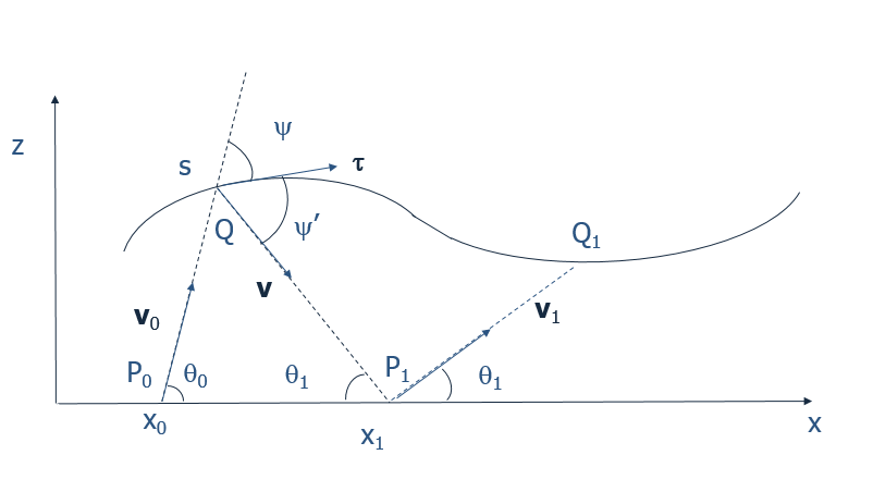
where x=x(s)𝑥𝑥𝑠x=x(s) is the inverse of the function s=s(x)𝑠𝑠𝑥s=s(x) defined by (4). Referring to Fig. 1 we define ψ𝜓\psi and ψsuperscript𝜓\psi^{\prime} the angles which the velocities 𝐯0subscript𝐯0{\bf v}_{0} and 𝐯𝐯{\bf v} of the incoming and outgoing ray at Q𝑄Q forms with the tangent τ𝜏\bf{\tau}.

Refer to caption
Refer to caption
Figure 1: Geometry of the reflections. On the right frame for n=0𝑛0n=0 we have α0=π/2ψsubscript𝛼0𝜋2𝜓\alpha_{0}=\pi/2-\psi, where ψ𝜓\psi is defined on the left frame.

The angles between the vectors 𝐯0subscript𝐯0-{\bf v}_{0} and 𝐯𝐯{\bf v} and the normal ν𝜈\bf{\nu} at Q𝑄Q are π/2ψ𝜋2𝜓\pi/2-\psi and π/2ψ𝜋2superscript𝜓\pi/2-\psi^{\prime}. As a consequence

𝐯0=(xx0,  1+ϵf(x))Th(x0,s)𝐯=(x1x,1ϵf(x))Th(x1,s)τ=(1,ϵf(x))T1+ϵ2f2(x)ν=(ϵf(x),1)T1+ϵ2f2(x)formulae-sequenceformulae-sequencesubscript𝐯0superscript𝑥subscript𝑥01italic-ϵ𝑓𝑥𝑇subscript𝑥0𝑠𝐯superscriptsubscript𝑥1𝑥1italic-ϵ𝑓𝑥𝑇subscript𝑥1𝑠𝜏superscript1italic-ϵsuperscript𝑓𝑥𝑇1superscriptitalic-ϵ2superscriptsuperscript𝑓2𝑥𝜈superscriptitalic-ϵsuperscript𝑓𝑥1𝑇1superscriptitalic-ϵ2superscriptsuperscript𝑓2𝑥\begin{split}{\bf v}_{0}&={(x-x_{0},\,\,1+\epsilon f(x))^{T}\over h(x_{0},s)}\qquad{\bf v}={(x_{1}-x,\,\,-1-\epsilon f(x))^{T}\over h(x_{1},s)}\\ \\ \bf{\tau}&={(1,\,\,\epsilon f^{\prime}(x))^{T}\over\sqrt{1+\epsilon^{2}{f^{\prime}}^{2}(x)}}\qquad{\bf{\nu}}={(\epsilon f^{\prime}(x),\,\,-1)^{T}\over\sqrt{1+\epsilon^{2}{f^{\prime}}^{2}(x)}}\end{split} (6)

We denote with 𝐯1subscript𝐯1{\bf v}_{1} the velocity of the ray reflected at P1subscript𝑃1P_{1} and with θ0subscript𝜃0\theta_{0} and θ1subscript𝜃1\theta_{1} the angles 𝐯0subscript𝐯0{\bf v}_{0} and 𝐯1subscript𝐯1{\bf v}_{1} form with the positive x𝑥x axis, see (1). The derivatives of h(x1,s)subscript𝑥1𝑠h(x_{1},s) and of h(x1,s)subscript𝑥1𝑠h(x_{1},s) are given by

sh(x0,s)=xx0+(1+ϵ(f(s))ϵf(x)h(x0,s)1+ϵ2f2(x)==𝐯0τ=cosψx0h(x0,s)=x0xh(x0,s)=vx 0=cosθ0sh(x1,s)=xx1+(1+ϵ(f(s))ϵf(x)h(x1,s)1+ϵ2f2(x)==𝐯τ=cosψx1h(x1,s)=x1xh(x0,s)=vx 1=cosθ1\begin{split}{\partial{}\over\partial{s}}\,h(x_{0},s)&={\,\,x-x_{0}+(1+\epsilon(f(s))\,\epsilon f^{\prime}(x)\,\,\over h(x_{0},s)\,\sqrt{1+\epsilon^{2}{f^{\prime}}^{2}(x)}}=\\ &\hskip 113.81102pt={\bf v}_{0}\cdot\bf{\tau}=\cos\psi\\ \\ {\partial{}\over\partial{x_{0}}}\,h(x_{0},s)&={x_{0}-x\over h(x_{0},s)}=-v_{x\,0}=-\cos\theta_{0}\\ \\ \\ {\partial{}\over\partial{s}}\,h(x_{1},s)&={\,\,x-x_{1}+(1+\epsilon(f(s))\,\epsilon f^{\prime}(x)\,\,\over h(x_{1},s)\,\sqrt{1+\epsilon^{2}{f^{\prime}}^{2}(x)}}=\\ &\hskip 113.81102pt={\bf v}\cdot\bf{\tau}=-\cos\psi^{\prime}\\ \\ {\partial{}\over\partial{x_{1}}}\,h(x_{1},s)&={x_{1}-x\over h(x_{0},s)}=v_{x\,1}=\cos\theta_{1}\end{split} (7)

The stationary point H𝐻H with respect to s𝑠s, when x0subscript𝑥0x_{0} and x1subscript𝑥1x_{1} are kept fixed, is met for s=s(x1,x2)𝑠subscript𝑠subscript𝑥1subscript𝑥2s=s_{*}(x_{1},x_{2}) where ψ=ψ𝜓superscript𝜓\psi=\psi^{\prime}, which corresponds to the the reflection condition. We introduce the function F(x0,x1)𝐹subscript𝑥0subscript𝑥1F(x_{0},x_{1}) equal to H𝐻H at the stationary point s=s(x0,x1)𝑠subscript𝑠subscript𝑥0subscript𝑥1s=s_{*}(x_{0},x_{1}) and compute its differential

F(x0,x1)=h(x0,x1,s)+h(x0,x1,s)dF(x0,x1)=vx 0dx0+vx 1dx1𝐹subscript𝑥0subscript𝑥1subscript𝑥0subscript𝑥1subscript𝑠subscript𝑥0subscript𝑥1subscript𝑠𝑑𝐹subscript𝑥0subscript𝑥1subscript𝑣𝑥 0𝑑subscript𝑥0subscript𝑣𝑥1𝑑subscript𝑥1\begin{split}F(x_{0},x_{1})&=h(x_{0},x_{1},s_{*})+h(x_{0},x_{1},s_{*})\\ \\ dF(x_{0},x_{1})&=-v_{x\,0}\,dx_{0}+v_{x\,1}\,dx_{1}\end{split} (8)

Equation (8) shows that F(x0,x1)𝐹subscript𝑥0subscript𝑥1F(x_{0},x_{1}) is the generating function of the canonical transformation M𝑀M from (x0,vx 0)subscript𝑥0subscript𝑣𝑥 0(x_{0},v_{x\,0}) to (x1,vx 1)subscript𝑥1subscript𝑣𝑥1(x_{1},\,v_{x\,1}). After n𝑛n iterations the phase space point (xn,vxn)subscript𝑥𝑛subscript𝑣𝑥𝑛(x_{n},v_{x\,n}) is reached and is mapped into (xn+1,vxn+1)subscript𝑥𝑛1subscript𝑣𝑥𝑛1(x_{n+1},v_{x\,n+1}) by M𝑀M. In the physical space the ray issued from the point Pn=(xn, 0)subscript𝑃𝑛subscript𝑥𝑛 0P_{n}=(x_{n},\,0) with horizontal velocity vxnsubscript𝑣𝑥𝑛v_{x\,n} is reflected at Qn=(xn,1+ϵf(xn))subscript𝑄𝑛subscript𝑥𝑛1italic-ϵ𝑓subscript𝑥𝑛Q_{n}=(x_{n},1+\epsilon f(x_{n})) and reaches Pn+1=(xn+1, 0)subscript𝑃𝑛1subscript𝑥𝑛1 0P_{n+1}=(x_{n+1},\,0) where the horizontal velocity after reflection is vxn+1subscript𝑣𝑥𝑛1v_{x\,n+1} see figure 1.

In order to obtain the map we first compute the time τ𝜏\tau needed for the transit between Pnsubscript𝑃𝑛P_{n} and Qnsubscript𝑄𝑛Q_{n}. Then we determine the horizontal component of the velocity vxn+1subscript𝑣𝑥𝑛1v_{x\,n+1} of the ray outgoing from Pn+1subscript𝑃𝑛1P_{n+1} which is equal to vxsubscript𝑣𝑥v_{x\,*}, where the velocity 𝐯subscript𝐯{\bf v}_{*} of the ray from Qnsubscript𝑄𝑛Q_{n} to Pn+1subscript𝑃𝑛1P_{n+1} is determined by the reflection condition 𝐯=𝐯n2ν(ν𝐯𝐧)subscript𝐯subscript𝐯𝑛2𝜈𝜈subscript𝐯𝐧{\bf v}_{*}={\bf v}_{n}-2\,\bf{\nu}\,(\bf{\nu}\cdot{\bf v}_{n}) and the normal of the guide at Qnsubscript𝑄𝑛Q_{n} is given by (6) . Finally xn+1xnsubscript𝑥𝑛1subscript𝑥𝑛x_{n+1}-x_{n} is given by vxnτ+vxn+1τsubscript𝑣𝑥𝑛𝜏subscript𝑣𝑥𝑛1superscript𝜏v_{x\,n}\tau+v_{x\,n+1}\tau^{\prime} where the transit time from τsuperscript𝜏\tau^{\prime} from Qnsubscript𝑄𝑛Q_{n} to Pn+1subscript𝑃𝑛1P_{n+1} is given by vzn+1τ=vznτsubscript𝑣𝑧𝑛1superscript𝜏subscript𝑣𝑧𝑛𝜏v_{z\,n+1}\,\tau^{\prime}=v_{z\,n}\tau.

vznτ=1+ϵf(xn+τvxn),vzn=1vxn2vxn+1=vxn2νx(ν𝐯𝐧)==vxn2ϵ2f2vxnϵfvzn1+ϵ2f2f=f(xn+τvxn)xn+1=xn+τ(vxn+vxn+1vznvzn+1)vzn+1=1vxn+12\begin{split}&v_{z\,n}\tau=1+\epsilon f(x_{n}+\tau v_{x\,n}),\qquad\quad v_{z\,n}=\sqrt{1-v_{x\,n}^{2}}\\ \\ &v_{x\,n+1}=v_{x\,n}-2\nu_{x}(\bf{\nu}\cdot{\bf v}_{n})=\\ &\hskip 102.43008pt=v_{x\,n}-2{\epsilon^{2}\,{f^{\prime}}^{2}\,v_{x\,n}-\epsilon\,f^{\prime}\,v_{z\,n}\over 1+\epsilon^{2}\,{f^{\prime}}^{2}}\\ &f^{\prime}=f^{\prime}(x_{n}+\tau\,v_{x\,n})\\ \\ &x_{n+1}=x_{n}+\tau\,\left({{v_{x\,n}\,+\,v_{x\,n+1}\,\,{v_{z\,n}\over v_{z\,n+1}}}}\right)\\ &\hskip 128.0374ptv_{z\,n+1}=\sqrt{1-v_{x\,n+1}^{2}}\end{split}\ (9)

The map (xn+1,vxn+1)=M(xn,vxn)subscript𝑥𝑛1subscript𝑣𝑥𝑛1𝑀subscript𝑥𝑛subscript𝑣𝑥𝑛(x_{n+1},\,v_{x\,n+1})=M(x_{n},\,v_{x\,n}) is symplectic since it is implicitly defined by the generating function F(xn,xn+1)𝐹subscript𝑥𝑛subscript𝑥𝑛1F(x_{n},\,x_{n+1}) according to vxn=F/xnsubscript𝑣𝑥𝑛𝐹subscript𝑥𝑛v_{x\,n}=-\partial F/\partial x_{n} and vxn+1=F/xn+1subscript𝑣𝑥𝑛1𝐹subscript𝑥𝑛1v_{x\,n+1}=\partial F/\partial x_{n+1}. The computation of the tangent map, is given in the Appendix.

III The 3D wave-guide

In this case we consider two planes z=0𝑧0z=0 and z=1𝑧1z=1 and the ray velocity is the unit vector 𝐯𝐯{\bf v} which can be written in Cartesian coordinates according to

𝐯=(vx,vy,vz)vz=1vx2+vy2formulae-sequence𝐯subscript𝑣𝑥subscript𝑣𝑦subscript𝑣𝑧subscript𝑣𝑧1superscriptsubscript𝑣𝑥2superscriptsubscript𝑣𝑦2\begin{split}{\bf v}&=(v_{x},\,v_{y},\,v_{z})\qquad\qquad v_{z}=\sqrt{1-v_{x}^{2}+v_{y}^{2}}\end{split} (10)

With 𝐯𝐯{\bf v} we denote the velocity of the ray reflected by the lower plane z=0𝑧0z=0 so that vz>0subscript𝑣𝑧0v_{z}>0. The time τ𝜏\tau between a reflection on the lower and upper plane is τvz=1𝜏subscript𝑣𝑧1\tau v_{z}=1 so that, choosing (x,y,vx,vy)𝑥𝑦subscript𝑣𝑥subscript𝑣𝑦(x,y,v_{x},v_{y}) as phase space coordinates, the map between two consecutive reflections reads

vxn+1=vxnvyn+1=vynxn+1=xn+2τvx,n=xn+2vxnvznyn+1=yn+2τvy,n=xn+2vynvznsubscript𝑣𝑥𝑛1subscript𝑣𝑥𝑛subscript𝑣𝑦𝑛1subscript𝑣𝑦𝑛subscript𝑥𝑛1subscript𝑥𝑛2𝜏subscript𝑣𝑥𝑛subscript𝑥𝑛2subscript𝑣𝑥𝑛subscript𝑣𝑧𝑛subscript𝑦𝑛1subscript𝑦𝑛2𝜏subscript𝑣𝑦𝑛subscript𝑥𝑛2subscript𝑣𝑦𝑛subscript𝑣𝑧𝑛\begin{split}v_{x\,n+1}&=v_{x\,n}\\ \\ v_{y\,n+1}&=v_{y\,n}\\ \\ x_{n+1}&=x_{n}+2\tau v_{x,n}=x_{n}+2{v_{x\,n}\over v_{z}\,n}\\ y_{n+1}&=y_{n}+2\tau v_{y,n}=x_{n}+2{v_{y\,n}\over v_{z}\,n}\end{split} (11)

If the map is defined on T2([π,π])×[1,1]2superscript𝑇2𝜋𝜋superscript112{T}^{2}([-\pi,\pi])\times[-1,1]^{2}, then vv,vysubscript𝑣𝑣subscript𝑣𝑦v_{v},\,v_{y} are the action variables and the interpolating Hamiltonian is H=21vx2vy2𝐻21superscriptsubscript𝑣𝑥2superscriptsubscript𝑣𝑦2H=-2\sqrt{1-v_{x}^{2}-v_{y}^{2}}. In the 3D waveguide the plane z=1𝑧1z=1 is corrugated, namely it is replaced by the surface

z=z(x,y)=1+ϵf(x,y)𝑧𝑧𝑥𝑦1italic-ϵ𝑓𝑥𝑦z=z(x,y)=1+\epsilon\,f(x,y) (12)

where f(x,y)𝑓𝑥𝑦f(x,y) is a periodic function in x𝑥x and y𝑦y with period 2π2𝜋2\pi and f>1𝑓1f>-1 with 0<ϵ<10italic-ϵ10<\epsilon<1. As a consequence the map describing the rays propagation can be defined on T2([π,π])×[1,1]2superscript𝑇2𝜋𝜋superscript112{T}^{2}([-\pi,\pi])\times[-1,1]^{2}. As in the 2D case we consider the sequence of points P0,P1,,Pn,subscript𝑃0subscript𝑃1subscript𝑃𝑛P_{0},P_{1},\ldots,P_{n},\ldots on the z=0𝑧0z=0 plane. We denote by Qnsubscript𝑄𝑛Q_{n} the point on the upper corrugated plane hit by the ray issued from Pnsubscript𝑃𝑛P_{n}, which after reflection reaches the z=0𝑧0z=0 plane at Pn+1subscript𝑃𝑛1P_{n+1}. The sequence points P0,P1,,Pn,subscript𝑃0subscriptsuperscript𝑃1subscriptsuperscript𝑃𝑛P_{0},P^{\prime}_{1},\ldots,P^{\prime}_{n},\ldots on the torus T2superscript𝑇2{T}^{2} is simply obtained taking the modulus with respect to 2π2𝜋2\pi so that (xn,yn)[π,π]subscriptsuperscript𝑥𝑛subscriptsuperscript𝑦𝑛𝜋𝜋(x^{\prime}_{n},y^{\prime}_{n})\in[-\pi,\pi]. Letting ν(𝐱,𝐲)𝜈𝐱𝐲\bf{\nu}(x,y) be the normal at the corrugated surface at the reflection point Q=(x,y,z)=1+ϵf(x,y)𝑄𝑥𝑦𝑧1italic-ϵ𝑓𝑥𝑦Q=(x,y,z)=1+\epsilon\,f(x,y), which explicitly reads

ν(x,y)=(ϵfx,ϵfy,1)T1+ϵ2(fx2+fy2)𝜈𝑥𝑦superscriptitalic-ϵsubscript𝑓𝑥italic-ϵsubscript𝑓𝑦1𝑇1superscriptitalic-ϵ2subscriptsuperscript𝑓2𝑥subscriptsuperscript𝑓2𝑦{\bf{\nu}}(x,y)={(\epsilon\,f_{x},\,\epsilon\,f_{y},\,-1)^{T}\over\sqrt{1+\epsilon^{2}(f^{2}_{x}+f^{2}_{y})}} (13)

The map (xn+1,yn+1,vxn+1,vyn+1)=M(xn,yn,vxn,vyn)subscript𝑥𝑛1subscript𝑦𝑛1subscript𝑣𝑥𝑛1subscript𝑣𝑦𝑛1𝑀subscript𝑥𝑛subscript𝑦𝑛subscript𝑣𝑥𝑛subscript𝑣𝑦𝑛(x_{n+1},\,y_{n+1},v_{x\,n+1},v_{y\,n+1})=M(x_{n},\,y_{n},v_{x\,n},v_{y\,n}) specifying the ray trajectory is given by

τvzn=1+ϵf(xn+τvxn,yn+τvyn)vzn=1vxn2vyn2vxn+1=vxn2νx(ν𝐯n)ν=ν(xn+τvxn,yn+τvyn)vyn+1=vyn2νy(ν𝐯𝐧)xn+1=xn+τ(vxn+vxn+1vznvzn+1)yn+1=yn+τ(vyn+vyn+1vznvzn+1)vzn+1=1vxn+12vyn+12formulae-sequence𝜏subscript𝑣𝑧𝑛1italic-ϵ𝑓subscript𝑥𝑛𝜏subscript𝑣𝑥𝑛subscript𝑦𝑛𝜏subscript𝑣𝑦𝑛subscript𝑣𝑧𝑛1superscriptsubscript𝑣𝑥𝑛2superscriptsubscript𝑣𝑦𝑛2subscript𝑣𝑥𝑛1subscript𝑣𝑥𝑛2subscript𝜈𝑥𝜈subscript𝐯𝑛𝜈𝜈subscript𝑥𝑛𝜏subscript𝑣𝑥𝑛subscript𝑦𝑛𝜏subscript𝑣𝑦𝑛subscript𝑣𝑦𝑛1subscript𝑣𝑦𝑛2subscript𝜈𝑦𝜈subscript𝐯𝐧subscript𝑥𝑛1subscript𝑥𝑛𝜏subscript𝑣𝑥𝑛subscript𝑣𝑥𝑛1subscript𝑣𝑧𝑛subscript𝑣𝑧𝑛1subscript𝑦𝑛1subscript𝑦𝑛𝜏subscript𝑣𝑦𝑛subscript𝑣𝑦𝑛1subscript𝑣𝑧𝑛subscript𝑣𝑧𝑛1subscript𝑣𝑧𝑛11superscriptsubscript𝑣𝑥𝑛12superscriptsubscript𝑣𝑦𝑛12\begin{split}&\tau\,v_{z\,n}=1+\epsilon f(x_{n}+\,\tau v_{x\,n},\,y_{n}+\tau\,v_{y\,n})\\ &\hskip 142.26378ptv_{z\,n}=\sqrt{1-v_{x\,n}^{2}-v_{y\,n}^{2}}\\ \\ &v_{x\,n+1}=v_{x\,n}-2\,\nu_{x}\,({\bf{\nu}}\cdot{\bf v}_{n})\qquad{\bf{\nu}}={\bf{\nu}}(x_{n}+\tau\,v_{x\,n},y_{n}+\tau\,v_{y\,n})\\ \\ &v_{y\,n+1}=v_{y\,n}-2\,\nu_{y}\,(\bf{\nu}\cdot{\bf v}_{n})\\ \\ &x_{n+1}=x_{n}+\tau\,\left({{v_{x\,n}+v_{x\,n+1}\,{v_{z\,n}\over v_{z\,n+1}}}}\right)\\ \\ &y_{n+1}=y_{n}+\tau\,\left({{v_{y\,n}+v_{y\,n+1}\,{v_{z\,n}\over v_{z\,n+1}}}}\right)\\ &\hskip 113.81102ptv_{z\,n+1}=\sqrt{1-v_{x\,n+1}^{2}-v_{y\,n+1}^{2}}\end{split} (14)

The first equation implicitly defines the propagation time τ𝜏\tau from Pnsubscript𝑃𝑛P_{n} to Qnsubscript𝑄𝑛Q_{n}, the remaining equations define the map M𝑀M which is symplectic. Indeed starting from the Fermat variational principle it is shown in appendix B that this map is obtained from a generating function F(xn,yn,xn+1,yn+1)𝐹subscript𝑥𝑛subscript𝑦𝑛subscript𝑥𝑛1subscript𝑦𝑛1F(x_{n},y_{n},x_{n+1},y_{n+1}). We do not quote in this case the expression of the tangent map since it is rather involved.

IV Dynamical indicators

We will present a numerical analysis of the 2D and 4D symplectic maps whose orbits describe the propagation of a ray in a 2D and 3D periodic waveguide. The stability analysis is intended to discriminate the regions of regular and chaotic motions using the recently introduced fast stability indicators, denominated Lyapunov and Reversibility error. The first one is closely related to fast Lyapunov indicator first proposed to analyze the growth of a small initial displacement. We shall not present a comparison with other fast indicators, because it has been performed for other models and since our indicators are independent from the initial displacement.

IV.1 Lyapounov error

For a symplectic map in a phase space of dimension 2d2𝑑2d map the Lyapunov error (LE) describes the growth of an initial random displacement ϵξitalic-ϵ𝜉\epsilon\,\bf{\xi} where ξ𝐑𝟐𝐝𝜉superscript𝐑2𝐝\bf{\xi}\in{R}^{2d} is a random vector with zero man and unit variance

ξ=0ξξT=Iformulae-sequencedelimited-⟨⟩𝜉0delimited-⟨⟩𝜉superscript𝜉𝑇𝐼\langle\,{\bf{\xi}}\,\rangle=0\qquad\qquad\langle\,{\bf{\xi}}\,{\bf{\xi}}^{T}\,\rangle={\char 73\relax} (15)

in the zero amplitude limit ϵ0italic-ϵ0\epsilon\to 0. Denoting with ΞnsubscriptΞ𝑛{\mathchar 28932\relax}_{n} the random displacement after n𝑛n iteration and with DM(x)𝐷𝑀𝑥DM(x) the tangent map

Ξn(𝐱)=limϵ0Mn(𝐱+ϵξ)Mn(𝐱)ϵ=Ln(𝐱)ξLn(𝐱)=DMn(𝐱)=DM(𝐱n1)Ln1(𝐱)subscriptΞ𝑛𝐱subscriptitalic-ϵ0superscript𝑀𝑛𝐱italic-ϵ𝜉superscript𝑀𝑛𝐱italic-ϵsubscript𝐿𝑛𝐱𝜉subscript𝐿𝑛𝐱𝐷superscript𝑀𝑛𝐱𝐷𝑀subscript𝐱𝑛1subscript𝐿𝑛1𝐱\begin{split}\Xi_{n}({\bf x})&=\lim_{\epsilon\to 0}\,{M^{n}({\bf x}+\epsilon{\bf{\xi}})-M^{n}({\bf x})\over\epsilon}={\char 76\relax}_{n}({\bf x})\,\bf{\xi}\\ \\ {\char 76\relax}_{n}({\bf x})&=DM^{n}({\bf x})={\char 68\relax}M({\bf x}_{n-1})\,{\char 76\relax}_{n-1}({\bf x})\end{split} (16)

The square of the Lyapunov error ELn(𝐱)subscript𝐸𝐿𝑛𝐱E_{L\,n}({\bf x}) is defined as as the variance of of the random vector ΞnsubscriptΞ𝑛\Xi_{n} or the trace of its covariance matrix

ELn2(𝐱)=ΞnΞn=Tr(Σn2)Σn2=ΞnΞnT=LnLnTformulae-sequencesubscriptsuperscript𝐸2𝐿𝑛𝐱delimited-⟨⟩subscriptΞ𝑛subscriptΞ𝑛TrsuperscriptsubscriptΣ𝑛2superscriptsubscriptΣ𝑛2delimited-⟨⟩subscriptΞ𝑛superscriptsubscriptΞ𝑛𝑇subscript𝐿𝑛superscriptsubscript𝐿𝑛𝑇E^{2}_{L\,n}({\bf x})=\langle\,\Xi_{n}\cdot\Xi_{n}\,\rangle=\,\hbox{Tr}\,(\Sigma_{n}^{2})\qquad\qquad\Sigma_{n}^{2}=\langle\,\Xi_{n}\,\Xi_{n}^{T}\,\rangle={\char 76\relax}_{n}\,{\char 76\relax}_{n}^{T} (17)

We might define the error ELn(𝐱,η)subscript𝐸𝐿𝑛𝐱𝜂E_{L\,n}({\bf x},\eta) for a given initial displacement ϵηitalic-ϵ𝜂\epsilon\eta with η=1norm𝜂1\|\eta\|=1, when ϵ0italic-ϵ0\epsilon\to 0. Its logarithm is just the Fast Lyapunov Indicator. We observe that letting 𝐞jsubscript𝐞𝑗{\bf e}_{j} be any orthonormal base the sum of ELn2(𝐱,𝐞j)subscriptsuperscript𝐸2𝐿𝑛𝐱subscript𝐞𝑗E^{2}_{L\,n}({\bf x},{\bf e}_{j}) extended to all the vectors of base is equal to ELn2(𝐱)subscriptsuperscript𝐸2𝐿𝑛𝐱E^{2}_{L\,n}({\bf x}). Our definition is independent from the initial displacement. An expression for the Lyapunov error equivalent to (17) is given by

ELn2(𝐱)=Tr(LnT(𝐱)Ln(𝐱))=Tr((DMn(𝐱))TDMn(𝐱))superscriptsubscript𝐸𝐿𝑛2𝐱Trsuperscriptsubscript𝐿𝑛𝑇𝐱subscript𝐿𝑛𝐱Trsuperscript𝐷superscript𝑀𝑛𝐱𝑇𝐷superscript𝑀𝑛𝐱E_{L\,n}^{2}({\bf x})=\,\hbox{Tr}\,({\char 76\relax}_{n}^{T}({\bf x})\,{\char 76\relax}_{n}({\bf x}))=\,\hbox{Tr}\,\Bigl{(}\,(DM^{n}({\bf x}))^{T}\,DM^{n}({\bf x})\,\Bigr{)} (18)

The stability analysis is performed by fixing n𝑛n and observing the change of EnLsuperscriptsubscript𝐸𝑛𝐿E_{n}^{L} when 𝐱𝐱{\bf x} varies on a 2D2𝐷2D phase plane (or a 2D manifold). Oseledet theorem Oseledet states that if 𝐱𝐱{\bf x} belongs to an ergodic component then (LnTLn)1/2nsuperscriptsuperscriptsubscript𝐿𝑛𝑇subscript𝐿𝑛12𝑛({\char 76\relax}_{n}^{T}\,{\char 76\relax}_{n})^{1/2n} has a limit WeΛWT𝑊superscript𝑒Λsuperscript𝑊𝑇{\char 87\relax}\,e^{\Lambda}\,{\char 87\relax}^{T} independent from 𝐱𝐱{\bf x}, where W𝑊{\char 87\relax} is an orthogonal matrix, ΛΛ\Lambda is diagonal and its entries λ1λ2λ2dsubscript𝜆1subscript𝜆2subscript𝜆2𝑑\lambda_{1}\geq\lambda_{2}\geq\ldots\geq\lambda_{2d} are the Lyapunov exponents with λd+k=λdk+1subscript𝜆𝑑𝑘subscript𝜆𝑑𝑘1\lambda_{d+k}=\,-\,\lambda_{d-k+1} and λk0subscript𝜆𝑘0\lambda_{k}\geq 0 for 1kd1𝑘𝑑1\leq k\leq d. As a consequence asymptotically ELn2e2nλ1+e2nλ2++e2nλ2de2nλ1similar-to-or-equalssubscriptsuperscript𝐸2𝐿𝑛superscript𝑒2𝑛subscript𝜆1superscript𝑒2𝑛subscript𝜆2superscript𝑒2𝑛subscript𝜆2𝑑similar-to-or-equalssuperscript𝑒2𝑛subscript𝜆1E^{2}_{L\,n}\,\simeq\,e^{2n\lambda_{1}}\,+\,e^{2n\lambda_{2}}\,+\,\ldots+e^{2n\lambda_{2d}}\,\simeq\,e^{2n\lambda_{1}} and more rigorously limn(ELn)1/n=λ1subscript𝑛superscriptsubscript𝐸𝐿𝑛1𝑛subscript𝜆1\lim_{n\to\infty}\,(E_{L\,n})^{1/n}=\lambda_{1}. However we are not interested in the n𝑛n\to\infty limit but rather on the dependence on 𝐱𝐱{\bf x} for a finite (possibly large) value of n𝑛n, when 𝐱𝐱{\bf x} varies in phase space.

IV.2 Reversibility error

We consider now the iteration of the map n𝑛n times followed by the iterations of the inverse map still n𝑛n times. Inserting a small additive noise at each forward and backward iteration, the final displacement with respect to the initial condition is a stochastic process, whose variance defines the square on the reversibility error (RE). More precisely letting 𝐱ϵ, 0=𝐱subscript𝐱italic-ϵ 0𝐱{\bf x}_{\epsilon,\,0}={\bf x} be the initial conditions, we consider the noisy orbit

𝐱ϵ,k=M(𝐱ϵ,k1)+ϵξkΞk=limϵ0𝐱ϵ,k𝐱kϵformulae-sequencesubscript𝐱italic-ϵ𝑘𝑀subscript𝐱italic-ϵ𝑘1italic-ϵsubscript𝜉𝑘subscriptΞ𝑘subscriptitalic-ϵ0subscript𝐱italic-ϵ𝑘subscript𝐱𝑘italic-ϵ{\bf x}_{\epsilon,\,k}=M({\bf x}_{\epsilon,\,k-1})+\epsilon\xi_{k}\qquad\qquad\Xi_{k}=\lim_{\epsilon\to 0}\,{{\bf x}_{\epsilon,\,k}-{\bf x}_{k}\over\epsilon} (19)

for k=1,,n𝑘1𝑛k=1,\ldots,n. Starting from 𝐱ϵ,nsubscript𝐱italic-ϵ𝑛{\bf x}_{\epsilon,\,n} we consider the reversed noisy orbit

𝐱ϵ,n,k=M1(𝐱ϵ,nk+1)+ϵξ𝐤Ξn,k=limϵ0𝐱ϵ,n,k𝐱nkϵsubscript𝐱italic-ϵ𝑛𝑘superscript𝑀1subscript𝐱italic-ϵ𝑛𝑘1italic-ϵsubscript𝜉𝐤subscriptΞ𝑛𝑘subscriptitalic-ϵ0subscript𝐱italic-ϵ𝑛𝑘subscript𝐱𝑛𝑘italic-ϵ\begin{split}{\bf x}_{\epsilon,\,n,-k}&=M^{-1}({\bf x}_{\epsilon,\,n-k+1})+\epsilon\bf{\xi}_{-k}\\ \\ \Xi_{n,\,-k}&=\lim_{\epsilon\to 0}\,{{\bf x}_{\epsilon,\,n,-k}-{\bf x}_{n-k}\over\epsilon}\end{split} (20)

The random vector ΞksubscriptΞ𝑘\Xi_{k} satisfies a linear recurrence with initial condition Ξ0=𝟎subscriptΞ00\Xi_{0}={\bf 0} whereas Ξn,ksubscriptΞ𝑛𝑘\Xi_{n,\,-k} satisfies another recurrence initialised by Ξn, 0=ΞnsubscriptΞ𝑛 0subscriptΞ𝑛\Xi_{n,\,0}=\Xi_{n}, see Panichi2017 ; Turchetti-INTECH for an explicit expression. We choose the random vectors ξ𝐤subscript𝜉𝐤\bf{\xi}_{k} and ξ𝐤subscript𝜉superscript𝐤\bf{\xi}_{-k^{\prime}} independent for k,k>0𝑘superscript𝑘0k,k^{\prime}>0

ξkξkT=Iδk,kξkξkT=Iδk,kξkξkT=ξkξkT=0formulae-sequencedelimited-⟨⟩subscript𝜉𝑘superscriptsubscript𝜉superscript𝑘𝑇𝐼subscript𝛿𝑘superscript𝑘delimited-⟨⟩subscript𝜉𝑘superscriptsubscript𝜉superscript𝑘𝑇𝐼subscript𝛿𝑘superscript𝑘delimited-⟨⟩subscript𝜉𝑘superscriptsubscript𝜉superscript𝑘𝑇delimited-⟨⟩subscript𝜉𝑘superscriptsubscript𝜉superscript𝑘𝑇0\begin{split}\langle\,{\bf{\xi}}_{k}\,{\bf{\xi}}_{k^{\prime}}^{T}\,\rangle&={\char 73\relax}\,\delta_{k,\,k^{\prime}}\qquad\langle\,{\bf{\xi}}_{-k}\,{\bf{\xi}}_{-k^{\prime}}^{T}\,\rangle={\char 73\relax}\,\delta_{k,\,k^{\prime}}\\ \\ \langle\,{\bf{\xi}}_{-k}\,{\bf{\xi}}_{k^{\prime}}^{T}\,\rangle&=\langle\,{\bf{\xi}}_{k}\,{\bf{\xi}}_{-k^{\prime}}^{T}\,\rangle=0\end{split} (21)

Letting ΞRn=Ξn,nsubscriptΞ𝑅𝑛subscriptΞ𝑛𝑛\Xi_{R\,n}=\Xi_{n,\,-n} be the stochastic displacement with respect to the initial condition 𝐱𝐱{\bf x} after reversing the orbit and ΣRn2(𝐱)subscriptsuperscriptΣ2𝑅𝑛𝐱\Sigma^{2}_{R\,n}({\bf x}) the corresponding covariance matrix we define the reversibility error ER(𝐱)subscript𝐸𝑅𝐱E_{R\,}({\bf x}) according to

ERn2(𝐱)=ΞRnΞRn=Tr(ΣRn2(𝐱))ΣRn2(𝐱)=ΞRn(ΞRn)Tsubscriptsuperscript𝐸2𝑅𝑛𝐱delimited-⟨⟩subscriptΞ𝑅𝑛subscriptΞ𝑅𝑛TrsubscriptsuperscriptΣ2𝑅𝑛𝐱subscriptsuperscriptΣ2𝑅𝑛𝐱delimited-⟨⟩subscriptΞ𝑅𝑛superscriptsubscriptΞ𝑅𝑛𝑇\begin{split}E^{2}_{R\,n}({\bf x})&=\langle\,\Xi_{R\,n}\cdot\Xi_{R\,n}\,\rangle=\,\hbox{Tr}\,\,\bigl{(}\Sigma^{2}_{R\,n}({\bf x})\,\bigr{)}\\ \\ \Sigma^{2}_{R\,n}({\bf x})&=\langle\,\Xi_{R\,n}\,(\Xi_{R\,n})^{T}\,\rangle\end{split} (22)

The covariance matrix that ΣRn2(𝐱)subscriptsuperscriptΣ2𝑅𝑛𝐱\Sigma^{2}_{R\,n}({\bf x}) can be expressed in terms of the tangent maps DMk(𝐱)𝐷superscript𝑀𝑘𝐱DM^{k}({\bf x}) and their inverses DMk(𝐱)𝐷superscript𝑀𝑘𝐱DM^{-k}({\bf x}). We do not quote their expression, which can be found in Panichi2015 ; Panichi2017 since it can be proved Turchetti-PhysicaD that for a symplectic map M𝑀M in R2dsuperscript𝑅2𝑑{R}^{2d} the error RE is related to LE by the following expression

ERn2(𝐱)=EL 02(𝐱)+ELn2(𝐱)+ 2k=1n1ELk2(𝐱)EL 02=Tr(I)=2dsuperscriptsubscript𝐸𝑅𝑛2𝐱superscriptsubscript𝐸𝐿 02𝐱superscriptsubscript𝐸𝐿𝑛2𝐱2superscriptsubscript𝑘1𝑛1superscriptsubscript𝐸𝐿𝑘2𝐱superscriptsubscript𝐸𝐿 02Tr𝐼2𝑑\begin{split}E_{R\,n}^{2}({\bf x})&=E_{L\,0}^{2}({\bf x})+E_{L\,n}^{2}({\bf x})\,+\,2\,\sum_{k=1}^{n-1}\,E_{L\,k}^{2}({\bf x})\\ E_{L\,0}^{2}&=\,\hbox{Tr}\,({\char 73\relax})=2d\end{split} (23)

or by the recurrence ERn2=ERn12+ELn2+ELn12subscriptsuperscript𝐸2𝑅𝑛subscriptsuperscript𝐸2𝑅𝑛1subscriptsuperscript𝐸2𝐿𝑛subscriptsuperscript𝐸2𝐿𝑛1E^{2}_{R\,n}=E^{2}_{R\,n-1}+E^{2}_{L\,n}+E^{2}_{L\,n-1} initialized by ER 02=0subscriptsuperscript𝐸2𝑅 00E^{2}_{R\,0}=0 and EL 02=2dsuperscriptsubscript𝐸𝐿 022𝑑E_{L\,0}^{2}=2d.

We finally define the reversibility error due to to round off (REM). Letting Mϵ(𝐱)subscript𝑀italic-ϵ𝐱M_{\epsilon}({\bf x}) the map computed with a finite precision ϵitalic-ϵ\epsilon (typically in the 8 bytes representation of reals ϵ1017)\epsilon\simeq 10^{-17}) and with Mϵ1subscriptsuperscript𝑀1italic-ϵM^{-1}_{\epsilon} the inverse of M𝑀M computed with finite accuracy, so that Mϵ1(Mϵ(𝐱))𝐱subscriptsuperscript𝑀1italic-ϵsubscript𝑀italic-ϵ𝐱𝐱M^{-1}_{\epsilon}\bigl{(}M_{\epsilon}({\bf x})\bigr{)}\not={\bf x}, the modified reversibility error (REM) is defined according to

E REM n(𝐱)=Mϵn(Mϵn(𝐱))𝐱ϵsubscript𝐸 REM 𝑛𝐱normsuperscriptsubscript𝑀italic-ϵ𝑛superscriptsubscript𝑀italic-ϵ𝑛𝐱𝐱italic-ϵE_{{\rmsmm\hbox{ {REM} }}\,n}({\bf x})={\left\|M_{\epsilon}^{-n}\bigl{(}M_{\epsilon}^{n}({\bf x})\bigr{)}-{\bf x}\right\|\over\epsilon} (24)

Letting 𝐱ϵ,n=Mϵ(𝐱ϵ,n1)subscript𝐱italic-ϵ𝑛subscript𝑀italic-ϵsubscript𝐱italic-ϵ𝑛1{\bf x}_{\epsilon,\,n}=M_{\epsilon}({\bf x}_{\epsilon,\,n-1}) be the orbit computed with round off, the local error (Mϵ(𝐱ϵ,n1)M(𝐱ϵ,n1))/ϵsubscript𝑀italic-ϵsubscript𝐱italic-ϵ𝑛1𝑀subscript𝐱italic-ϵ𝑛1italic-ϵ\bigl{(}\,M_{\epsilon}({\bf x}_{\epsilon,\,n-1})-M({\bf x}_{\epsilon,\,n-1})\,\bigr{)}/\epsilon is similar to a random vector, possibly correlated, if the map has a sufficiently high computational complexity, see Hairer2006 ; Zanlungo . The difference with respect to the additive noise, we have considered to define RE, is that we have just a single realization. As a consequence even though the behaviour of RE and REM is similar, the last one exhibits large fluctuations, when n𝑛n varies. On the other side the computation of REM is really trivial since it requires a few lines of code, if the inverse map is available. This is the case of the reflection map for a waveguide. Indeed to reverse the evolution after n𝑛n iterations we must simply change the sign of the horizontal velocity components(s) and iterate again the same map n𝑛n times.

IV.3 Integrable and quasi-integrable maps

The computation of LE and RE can be analytically performed for an integrable map. If the 2D map is a rotation M(𝐱)=R(ω)𝐱𝑀𝐱𝑅𝜔𝐱M({\bf x})={\char 82\relax}(\omega){\bf x} then ELn2=2superscriptsubscript𝐸𝐿𝑛22E_{L\,n}^{2}=2 and ERn2=4nsuperscriptsubscript𝐸𝑅𝑛24𝑛E_{R\,n}^{2}=4n. If the map M𝑀M is linearly conjugated to a rotation by 𝐱=T𝐗𝐱𝑇𝐗{\bf x}={\char 84\relax}{\bf X} then the map in normal coordinates is R(ω)𝐗𝑅𝜔𝐗{\char 82\relax}(\omega){\bf X} and M(𝐱)=TR(ω)T1𝐱𝑀𝐱𝑇𝑅𝜔superscript𝑇1𝐱M({\bf x})={\char 84\relax}{\char 82\relax}(\omega){\char 84\relax}^{-1}{\bf x} in the given coordinates. The loss of symmetry in the coordinates 𝐱𝐱{\bf x} induces periodic oscillations (ELn2=A+(2A)cos(ωn)(E^{2}_{L\,n}=A+(2-A)\cos(\omega n) with A2𝐴2A\geq 2 and ERnsubscript𝐸𝑅𝑛E_{R\,n} has a linear growth with oscillations. A map M(𝐱)𝑀𝐱M({\bf x}) is integrable if there is a coordinate transformation 𝐱=T(𝐗)𝐱𝑇𝐗{\bf x}=T({\bf X}) such that the map becomes N(𝐗)=R(Ω(J))𝐗𝑁𝐗𝑅Ω𝐽𝐗N({\bf X})=R(\Omega(J))\,{\bf X} where the frequency depends on the action J=12𝐗2𝐽12superscriptnorm𝐗2J={1\over 2}\|{\bf X}\|^{2}. In this case M(𝐱)=TN(Ω(J))T1(𝐱)𝑀𝐱𝑇𝑁Ω𝐽superscript𝑇1𝐱M({\bf x})=T\circ N(\Omega(J))\circ\,T^{-1}({\bf x}). The Lyapunov and reversibility errors LE and LE, depend on the initial condition and in the normal coordinates 𝐗𝐗{\bf X} they grow according to

ELn2(𝐗)=2+(2JΩ(J)n)2ERn2(𝐗)4n+2(2JΩ(J))2(n33+n6)superscriptsubscript𝐸𝐿𝑛2𝐗2superscript2𝐽superscriptΩ𝐽𝑛2superscriptsubscript𝐸𝑅𝑛2𝐗4𝑛2superscript2𝐽superscriptΩ𝐽2superscript𝑛33𝑛6\begin{split}E_{L\,n}^{2}({\bf X})&=2+(2J\,\Omega^{\prime}(J)\,n)^{2}\\ E_{R\,n}^{2}({\bf X})&4n+2\,\bigl{(}2J\Omega^{\prime}(J)\bigr{)}^{2}\left({{{n^{3}\over 3}+{n\over 6}}}\right)\end{split} (25)

The Lyapunov error LE𝐿𝐸LE in the coordinates 𝐱𝐱{\bf x} exhibits a linear growth with oscillations, due to the loss of rotational symmetry as in the linear case and we have

ELn2(𝐱)=α0(n)+nJΩ(J)α1(n)+(JΩ(J)n)2α2(n)superscriptsubscript𝐸𝐿𝑛2𝐱subscript𝛼0𝑛𝑛𝐽superscriptΩ𝐽subscript𝛼1𝑛superscript𝐽superscriptΩ𝐽𝑛2subscript𝛼2𝑛\begin{split}E_{L\,n}^{2}({\bf x})=\alpha_{0}(n)+n\,J\,\Omega^{\prime}(J)\,\alpha_{1}(n)\\ +\bigl{(}J\,\Omega^{\prime}(J)\,n\bigr{)}^{2}\,\alpha_{2}(n)\end{split} (26)

where J=12T1(𝐱)2𝐽12superscriptnormsuperscript𝑇1𝐱2J={1\over 2}\|T^{-1}({\bf x})\|^{2} and αksubscript𝛼𝑘\alpha_{k} are periodic functions of n𝑛n with frequency Ω(J)Ω𝐽\Omega(J). According to equation (23) the square of the reversibility error RE grows as n3superscript𝑛3n^{3} with oscillations whose amplitude grows as n2superscript𝑛2n^{2}. If the map is quasi integrable as in the neighborhood of an elliptic fixed point at 𝐱subscript𝐱{\bf x}_{*} with non-resonant frequency, then it is conjugated with its normal form up to a remainder which can be made exponentially small with ea/rαsimilar-toabsentsuperscript𝑒𝑎superscript𝑟𝛼\sim e^{-a/r^{\alpha}} where r=𝐱𝐱𝑟norm𝐱subscript𝐱r=\|{\bf x}-{\bf x}_{*}\|. Exponentially small estimates for the remainder can also be obtained for the error on the tangent map.
If the system has an hyperbolic point at 𝐱=(x,p)T=𝟎𝐱superscript𝑥𝑝𝑇0{\bf x}=(x,p)^{T}={\bf 0} and it is linear then M(𝐱)=(eλx,eλp)T𝑀𝐱superscriptsuperscript𝑒𝜆𝑥superscript𝑒𝜆𝑝𝑇M({\bf x})=(e^{-\lambda}x,\,e^{\lambda}p)^{T} and ELn2=2ch(2nλ)e2nλsuperscriptsubscript𝐸𝐿𝑛22ch2𝑛𝜆similar-tosuperscript𝑒2𝑛𝜆E_{L\,n}^{2}=2\,\hbox{ch}(2n\lambda)\sim e^{2n\lambda}. If the system is non linear, in normal coordinates the map is Xn+1=eλ(XP)Xnsubscript𝑋𝑛1superscript𝑒𝜆𝑋𝑃subscript𝑋𝑛X_{n+1}=e^{-\lambda(XP)}X_{n} and Pn+1=eλ(XY)Pnsubscript𝑃𝑛1superscript𝑒𝜆𝑋𝑌subscript𝑃𝑛P_{n+1}=e^{\lambda(XY)}P_{n} with initial condition 𝐗0=(X,P)Tsubscript𝐗0superscript𝑋𝑃𝑇{\bf X}_{0}=(X,P)^{T}. The Lyapunov error is

ELn2(𝐗)=e2nλ(1+nXPλ(XP))2(1+O(e2λn))superscriptsubscript𝐸𝐿𝑛2𝐗superscript𝑒2𝑛𝜆superscript1𝑛𝑋𝑃superscript𝜆𝑋𝑃21𝑂superscript𝑒2𝜆𝑛\begin{split}E_{L\,n}^{2}({\bf X})=e^{2n\,\lambda}\Bigl{(}1+nXP\,\lambda^{\prime}(XP)\Bigr{)}^{2}\,\,\Bigl{(}1+O\bigl{(}e^{-2\lambda\,n}\bigr{)}\,\Bigr{)}\end{split} (27)

The square of LE near an elliptic equilibrium point for a generic symplectic map grows linearly with oscillations, the square of RE grows as n3superscript𝑛3n^{3} with oscillations whose amplitude grows as n2superscript𝑛2n^{2} so that asymptotically they become negligible. Near a hyperbolic point LE and RE have the same exponential growth. Finally REM behaves just as RE but exhibits large fluctuations. Right after the break up of the invariant curves surrounding an elliptic point sticky orbits are found and the indicators have initially a power law growth followed by an exponential growth. We conclude that RE is the smoothest indicator, since LE can exhibit oscillations and REM is affected by large fluctuations. However if we choose a fixed value of n𝑛n large enough, the portraits all these indicators in a chosen plane of phase space are very similar.

V The model of a 2D waveguide

We present first a numerical analysis of the orbits for the map of the 2D waveguide where the corrugation is given by

f(x)=cos(x)𝑓𝑥𝑥f(x)=\cos(x) (28)

The phase space coordinates are (x,vx)𝑥subscript𝑣𝑥(x,\,v_{x}) and the map is defined on the cylinder T([π,π])×[1,1]𝑇𝜋𝜋11{T}([-\pi,\pi])\times[-1,1] where T(([π,π]){T}(([-\pi,\pi]) is the interval [π,π]𝜋𝜋[-\pi,\,\pi] with identified ends. The map has an elliptic fixed point at x=0,vx=0formulae-sequence𝑥0subscript𝑣𝑥0x=0,\,v_{x}=0 where f(x)𝑓𝑥f(x) has a maximum and is approximated by f(x)=112x2+O(x4)𝑓𝑥112superscript𝑥2𝑂superscript𝑥4f(x)=1-{1\over 2}x^{2}+O(x^{4}). We expand the map retaining only the linear terms in x,vx𝑥subscript𝑣𝑥x,\,v_{x}. The first equation in (9) gives τ=1+ϵ𝜏1italic-ϵ\tau=1+\epsilon neglecting second order terms in x𝑥x and vxsubscript𝑣𝑥v_{x}. Since f(x)=x+O(x3)superscript𝑓𝑥𝑥𝑂superscript𝑥3f^{\prime}(x)=-x+O(x^{3}) in the second equation the square of fsuperscript𝑓f^{\prime} are neglected and vznsubscript𝑣𝑧𝑛v_{z\,n} is replaced with 1. Accordingly the second and third equations become

vxn+1=vxn2ϵ(xn+τvxn)xn+1=xn+τ(vxn+vxn+1)subscript𝑣𝑥𝑛1subscript𝑣𝑥𝑛2italic-ϵsubscript𝑥𝑛𝜏subscript𝑣𝑥𝑛subscript𝑥𝑛1subscript𝑥𝑛𝜏subscript𝑣𝑥𝑛subscript𝑣𝑥𝑛1\begin{split}v_{x\,n+1}&=v_{x\,n}-2\epsilon\,(x_{n}+\tau v_{x\,n})\\ \quad x_{n+1}&=x_{n}+\tau(v_{x\,n}+v_{x\,n+1})\end{split} (29)

Letting M(𝐱)=L𝐱𝑀𝐱𝐿𝐱M({\bf x})={\char 76\relax}{\bf x} be the linear map we have

L=(12ϵτ2τ2ϵτ22ϵ12ϵτ)𝐿matrix12italic-ϵ𝜏2𝜏2italic-ϵsuperscript𝜏2missing-subexpression2italic-ϵ12italic-ϵ𝜏{\char 76\relax}=\begin{pmatrix}1-2\epsilon\,\tau&2\tau-2\epsilon\,\tau^{2}\\ \\ -2\,\epsilon&1-2\epsilon\,\tau\end{pmatrix} (30)

so that detL=1det𝐿1\,\hbox{det}\,{\char 76\relax}=1 and 12TrL=12ϵτ12Tr𝐿12italic-ϵ𝜏{1\over 2}\,\,\hbox{Tr}\,\,{\char 76\relax}=1-2\epsilon\,\tau. The map is conjugated to a rotation L=VR(ω)V1𝐿𝑉𝑅𝜔superscript𝑉1{\char 76\relax}={\char 86\relax}{\char 82\relax}(\omega)\,{\char 86\relax}^{-1} where sin2(ω/2)=τϵ=ϵ(1+ϵ)superscript2𝜔2𝜏italic-ϵitalic-ϵ1italic-ϵ\sin^{2}(\omega/2)=\tau\epsilon=\epsilon(1+\epsilon). In this case we have Ln=Lnsubscript𝐿𝑛superscript𝐿𝑛{\char 76\relax}_{n}={\char 76\relax}^{n}. Close to x=0𝑥0x=0 the profile z=1+ϵϵx2/2𝑧1italic-ϵitalic-ϵsuperscript𝑥22z=1+\epsilon-\epsilon x^{2}/2 is a concave mirror and the elliptical trajectories in phase space (x,vx)𝑥subscript𝑣𝑥(x,v_{x}) correspond to caustics in configuration space, namely the plane (x,z)𝑥𝑧(x,z) where the rays propagate. Close to x=π𝑥𝜋x=\pi the profile is approximated by z=1ϵ+12ϵ(xπ)2+O(xπ)4𝑧1italic-ϵ12italic-ϵsuperscript𝑥𝜋2𝑂superscript𝑥𝜋4z=1-\epsilon+{1\over 2}\,\epsilon\,(x-\pi)^{2}+O(x-\pi)^{4} so that τ=1ϵ𝜏1italic-ϵ\tau=1-\epsilon and the linearized map is (xn+1,vxn+1)T=L(xn,vxn)Tsuperscriptsubscript𝑥𝑛1subscript𝑣𝑥𝑛1𝑇𝐿superscriptsubscript𝑥𝑛subscript𝑣𝑥𝑛𝑇(x_{n+1},v_{x\,n+1})^{T}={\char 76\relax}\,(x_{n},\,v_{x\,n})^{T}, where L𝐿{\char 76\relax} is given by (29) with ϵϵitalic-ϵitalic-ϵ\epsilon\to-\epsilon. The map L𝐿{\char 76\relax} is conjugated to a hyperbolic rotation RH(α)subscript𝑅𝐻𝛼{\char 82\relax}_{H}(\alpha) where sh2(α/2)=ϵτ=ϵ(1ϵ)superscriptsh2𝛼2italic-ϵ𝜏italic-ϵ1italic-ϵ\hbox{sh}^{2}(\alpha/2)=\epsilon\tau=\epsilon(1-\epsilon).
Near x=π𝑥𝜋x=\pi the wave guide corresponds to an optical system given by a plane and convex mirror ref0 .
The map defined by (9) was computed by solving the equation for τ𝜏\tau with the bisection method initialized by τ1=0.5/1vxn2subscript𝜏10.51superscriptsubscript𝑣𝑥𝑛2\tau_{1}=0.5/\sqrt{1-v_{x\,n}^{2}} and τ2=1.5/1vxn2subscript𝜏21.51superscriptsubscript𝑣𝑥𝑛2\tau_{2}=1.5/\sqrt{1-v_{x\,n}^{2}}. The convergence is achieved also when vxnsubscript𝑣𝑥𝑛v_{x\,n} approaches 111 or 11-1. The number of iterations to reach machine accuracy varies between 40 and 60. Newton’s method is faster and machine accuracy is reached in less 10 iterations, but convergence problems are met when vxnsubscript𝑣𝑥𝑛v_{x\,n} approaches 111 or 11-1.

Refer to caption
(a)
Refer to caption
(b)
Refer to caption
(c)
Refer to caption
(d)
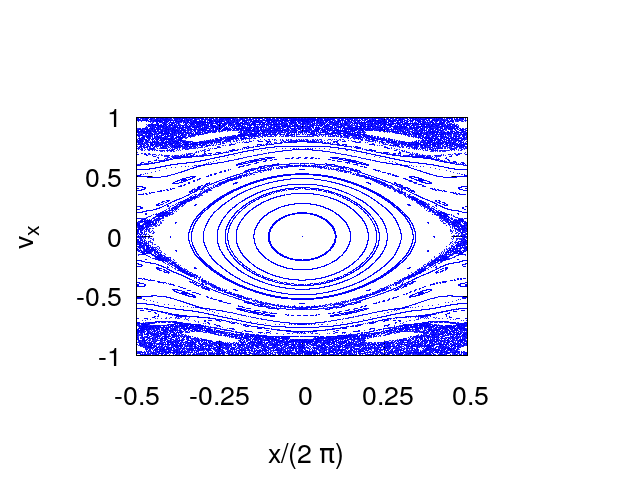
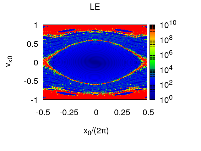
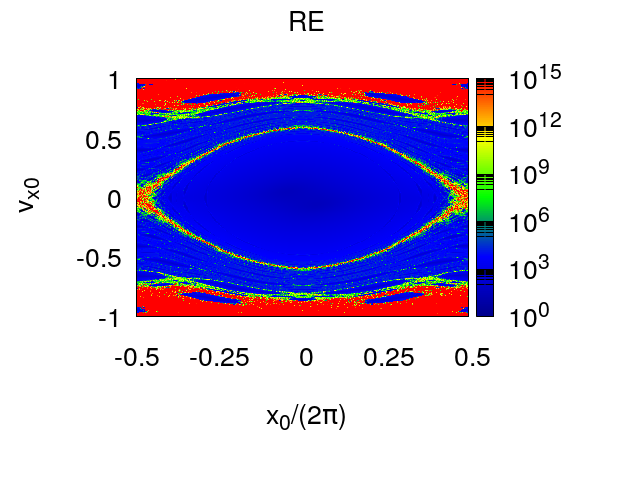
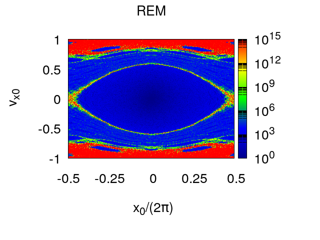
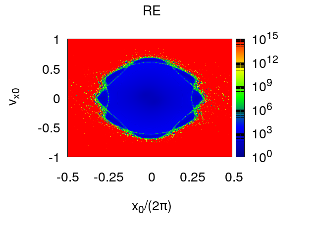
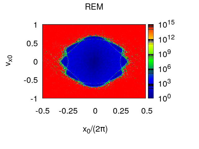
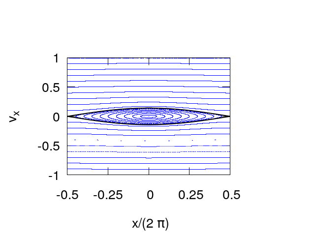
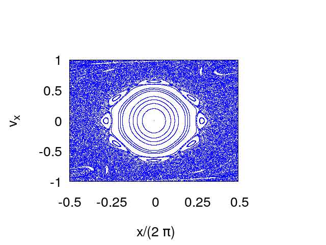
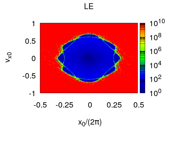
Figure 2: From the top: (a) Phase portrait of the map for the 2D waveguide with corrugation z=1+ϵcos(x)𝑧1italic-ϵ𝑥z=1+\epsilon\cos(x) and ϵ=0.1italic-ϵ0.1\epsilon=0.1. (b) Colour plot of LE for N=200𝑁200N=200 iterations of the map. (c) Plot of RE for N=200𝑁200N=200 iterations of the map. (d) Plot of REM for N=200𝑁200N=200 iterations of the map.

We have also computed the tangent map and the explicit expression is written in Appendix A. Writing the implicit equation G(xn,vxn,τ)=0𝐺subscript𝑥𝑛subscript𝑣𝑥𝑛𝜏0G(x_{n},v_{x\,n},\tau)=0, the solution is not defined if G/τ=0𝐺𝜏0\partial G/\partial\tau=0 a condition numerically never met. In figures 2, 3 we compare the phase portraits with the colour plots of LE, RE and REM for two different values of the corrugation amplitude ϵ=0.1, 0.2italic-ϵ0.10.2\epsilon=0.1,\,0.2 respectively and orbits length N=200𝑁200N=200. The correspondence is quite good and RE appears to be the smoothest indicator since it is free from oscillations and fluctuations when n𝑛n varies. Increasing N𝑁N does not change the plots significantly. Higher values of N𝑁N are needed if one wishes to observe details in small regions where the transition from ordered to chaotic orbits occurs.
Refer to caption
(a)
Refer to caption
(b)
Refer to caption
(c)
Refer to caption
(d)
Figure 3: From the top: (a) Phase portrait of the map for the 2D waveguide with corrugation z=1+ϵcos(x)𝑧1italic-ϵ𝑥z=1+\epsilon\cos(x) and ϵ=0.2italic-ϵ0.2\epsilon=0.2. (b) Colour plot of LE for N=200𝑁200N=200 iterations of the map. (c) Plot of RE for N=200𝑁200N=200 iterations of the map. (d) Plot of REM for N=200𝑁200N=200 iterations of the map.

VI The 3D model

For the 3D waveguide we choose the corrugated profile according to

f(x,y)=cosxcosy=12cos(x+y)+12cos(xy)𝑓𝑥𝑦𝑥𝑦12𝑥𝑦12𝑥𝑦f(x,y)=\cos x\,\,\cos y={1\over 2}\cos(x+y)+{1\over 2}\cos(x-y) (31)

We remark first that for initial conditions y0=vy 0=0subscript𝑦0subscript𝑣𝑦 00y_{0}=v_{y\,0}=0 we are back to the 2D case. If we choose x0=y0subscript𝑥0subscript𝑦0x_{0}=y_{0} and vx 0=vy 0subscript𝑣𝑥 0subscript𝑣𝑦 0v_{x\,0}=v_{y\,0} the ray propagates in the x=y𝑥𝑦x=y plane as for 2D waveguide. After a rotation of π/4𝜋4\pi/4 the ray propagates on the x,zsuperscript𝑥𝑧x^{\prime},z plane where x=2x,vx=2vxformulae-sequencesuperscript𝑥2𝑥superscriptsubscript𝑣𝑥2subscript𝑣𝑥x^{\prime}=\sqrt{2}\,\,x,\,\,v_{x}^{\prime}=\sqrt{2}\,\,v_{x}, the corrugation function depends only on xsuperscript𝑥x^{\prime} as f=12[cos(2x)+1]𝑓12delimited-[]2superscript𝑥1f={1\over 2}\bigl{[}\cos(\sqrt{2\,}\,x^{\prime}\,)+1\bigr{]} and its period is 2π2𝜋\sqrt{2}\,\,\pi. When the ray does not propagate in a plane the simplest case to analyze corresponds to the almost vertical propagation of the ray close to to a critical point (xc,yc)subscript𝑥𝑐subscript𝑦𝑐(x_{c},y_{c}) of the corrugation function, where gradf=0grad𝑓0\hbox{grad}f=0. The fixed point of the map (xc,yc,vx=0,vy=0)formulae-sequencesubscript𝑥𝑐subscript𝑦𝑐subscript𝑣𝑥0subscript𝑣𝑦0(x_{c},y_{c},v_{x}=0,\,v_{y}=0) is elliptic if f𝑓f has a maximum at (xc,yc)subscript𝑥𝑐subscript𝑦𝑐(x_{c},y_{c}) and the corrugated surface near (xc,yc)subscript𝑥𝑐subscript𝑦𝑐(x_{c},y_{c}) behaves as a concave mirror.
If f𝑓f has a minimum at (xc,y)(x_{c},\,y_{)} then the surface behaves as a convex mirror and and the critical point of the map is hyperbolic. For our model near x=y=0𝑥𝑦0x=y=0 we have f112(x2+y2)similar-to-or-equals𝑓112superscript𝑥2superscript𝑦2f\simeq 1-{1\over 2}(x^{2}+y^{2}). The linearized map becomes

vxn+1=vxn2ϵ(xn+τvxn)xn+1=xn+τ(vxn+vxn+1)vyn+1=vyn2ϵ(yn+τvyn)yn+1=yn+τ(vyn+vyn+1)subscript𝑣𝑥𝑛1subscript𝑣𝑥𝑛2italic-ϵsubscript𝑥𝑛𝜏subscript𝑣𝑥𝑛subscript𝑥𝑛1subscript𝑥𝑛𝜏subscript𝑣𝑥𝑛subscript𝑣𝑥𝑛1subscript𝑣𝑦𝑛1subscript𝑣𝑦𝑛2italic-ϵsubscript𝑦𝑛𝜏subscript𝑣𝑦𝑛subscript𝑦𝑛1subscript𝑦𝑛𝜏subscript𝑣𝑦𝑛subscript𝑣𝑦𝑛1\begin{split}v_{x\,n+1}&=v_{x\,n}-2\epsilon\,(x_{n}+\tau v_{x\,n})\\ x_{n+1}&=x_{n}+\tau(v_{x\,n}+v_{x\,n+1})\\ v_{y\,n+1}&=v_{y\,n}-2\epsilon\,(y_{n}+\tau v_{y\,n})\\ y_{n+1}&=y_{n}+\tau(v_{y\,n}+v_{y\,n+1})\end{split} (32)

where τ=1+ϵ𝜏1italic-ϵ\tau=1+\epsilon. Since τ𝜏\tau is constant in this approximation the maps in the (x,vx)𝑥subscript𝑣𝑥(x,v_{x}) and (y,vy)𝑦subscript𝑣𝑦(y,v_{y}) phase planes decouple and each of them is area preserving. The linear frequencies are equal and given by sin2(ω/2)=ϵτsuperscript2𝜔2italic-ϵ𝜏\sin^{2}(\omega/2)=\epsilon\,\tau as for the 2D case. The degeneracy can be removed choosing for instance f(x,y)=cosx+Acosy𝑓𝑥𝑦𝑥𝐴𝑦f(x,y)=\cos x+A\cos y.
Near x=0,y=πformulae-sequence𝑥0𝑦𝜋x=0,y=\pi we have f1+12(x2+(yπ)2)similar-to-or-equals𝑓112superscript𝑥2superscript𝑦𝜋2f\simeq 1+{1\over 2}(x^{2}+(y-\pi)^{2}) and the fixed point of the map is hyperbolic. More generally (0,0),(±π,±π),(±π,π)00plus-or-minus𝜋plus-or-minus𝜋plus-or-minus𝜋minus-or-plus𝜋(0,0),\,(\pm\pi,\,\pm\pi),\,(\pm\pi,\,\mp\pi) are elliptic and (0,±π),(±π,0)0plus-or-minus𝜋plus-or-minus𝜋0(0,\pm\pi),\,(\pm\pi,0) are hyperbolic. We do not examine the projections of individual orbits on 2D phase space planes nor on 3D hyperplanes. Close to the elliptic fixed points single 2D tori are recognisable in the projections on 3D hyperplanes and even 2D phase space planes, but the projection of several orbits does not provide any useful information. For this reason we show here the plots of our short term indicators LE, RE and REM of orbits whose initial points belong to 2D phase planes. The plots are obtained by computing our indicators for initial conditions (x0,vx 0,y0,vy 0)subscript𝑥0subscript𝑣𝑥 0subscript𝑦0subscript𝑣𝑦 0(x_{0},v_{x\,0},y_{0},v_{y\,0}) in a family of 2D phase planes where y0subscript𝑦0y_{0} and vy 0/vx 0subscript𝑣𝑦 0subscript𝑣𝑥 0v_{y\,0}/v_{x\,0} are kept fixed. Letting vx 0=v0cos(ϕ0)subscript𝑣𝑥 0subscript𝑣0subscriptitalic-ϕ0v_{x\,0}=v_{0}\cos(\phi_{0}) and vy 0=v0sin(ϕ0)subscript𝑣𝑦 0subscript𝑣0subscriptitalic-ϕ0v_{y\,0}=v_{0}\sin(\phi_{0}) we compare the errors for fixed values of y0,ϕ0subscript𝑦0subscriptitalic-ϕ0y_{0},\,\phi_{0} letting x0,v0subscript𝑥0subscript𝑣0x_{0},v_{0} which vary in [π,π]×[1,1]𝜋𝜋11[-\pi,\,\pi]\times[-1,1], where we choose a regular grid of Ng×Ngsubscript𝑁𝑔subscript𝑁𝑔N_{g}\times N_{g} points. We have fixed the corrugation amplitude at ϵ=0.1italic-ϵ0.1\epsilon=0.1 because there is a good balance between regular and chaotic regions. In figures 4, 5, 6 we compare the errors LE, RE, REM in a logarithmic color scale by choosing and y0=0subscript𝑦00y_{0}=0 ϕ0=π/4,π/2, 3π/4subscriptitalic-ϕ0𝜋4𝜋23𝜋4\phi_{0}=\,\pi/4,\,\pi/2,\,3\pi/4. We have computed LE by using the shadow orbit to evaluate the tangent map, namely we have replaced the partial derivatives Mi/xjsubscript𝑀𝑖subscript𝑥𝑗\partial M_{i}/\partial x_{j} by finite differences, avoiding the cumbersome analytic evaluation. To this and we have chosen four different initial conditions 𝐱0+𝐞jδsubscript𝐱0subscript𝐞𝑗𝛿{\bf x}_{0}+{\bf e}_{j}\,\,\delta for j4absent𝑗4\leq j\leq 4 where 𝐞jsubscript𝐞𝑗{\bf e}_{j} are the orthonormal base vectors in R4superscript𝑅4{R}^{4} namely (𝐞j)k=δjksubscriptsubscript𝐞𝑗𝑘subscript𝛿subscript𝑗𝑘({\bf e}_{j})_{k}=\delta_{j_{k}}. The tangent map is approximated by

DMn(𝐱0)𝐞j𝐰j(n)Mn(𝐱0+𝐞jδ)Mn(𝐱0)δsimilar-to-or-equals𝐷superscript𝑀𝑛subscript𝐱0subscript𝐞𝑗subscript𝐰𝑗𝑛superscript𝑀𝑛subscript𝐱0subscript𝐞𝑗𝛿superscript𝑀𝑛subscript𝐱0𝛿DM^{n}({\bf x}_{0}){\bf e}_{j}\simeq{\bf w}_{j}(n)\equiv{M^{n}({\bf x}_{0}+{\bf e}_{j}\,\delta)-M^{n}({\bf x}_{0})\over\delta} (33)

so that the Lyapunov error becomes

ELn2j=14𝐰j(n)2similar-to-or-equalssubscriptsuperscript𝐸2𝐿𝑛superscriptsubscript𝑗14superscriptnormsubscript𝐰𝑗𝑛2E^{2}_{L\,n}\simeq\sum_{j=1}^{4}\,\|{\bf w}_{j}(n)\|^{2} (34)

the discrepancy is of order δ𝛿\delta and the choice δ=1014𝛿superscript1014\delta=10^{-14} was made, using double precision accuracy. For ϕ0=0subscriptitalic-ϕ00\phi_{0}=0 we recover the plot computed with the tangent map for the 2D waveguide since the ray propagates in the x,z𝑥𝑧x,z plane, but only if the sum in equation (34) runs only up to 2 (corresponding to the phase space coordinates to x,vx𝑥subscript𝑣𝑥x,v_{x}). This is equivalent to define LE by replacing DMn𝐷superscript𝑀𝑛DM^{n} with its first 2×2222\times 2 block, which corresponds to tangent map for the 2D map. Indeed even though the orbits of the 2D and 4D map are the same for initial conditions y0=vy 0=0subscript𝑦0subscript𝑣𝑦 00y_{0}=v_{y\,0}=0, the components of 4D tangent map, not belonging the 2×2222\times 2 block, are non zero. On the contrary REM does not change with respect to 2D map, because the (x,vx)𝑥subscript𝑣𝑥(x,\,v_{x}) plane is invariant. To recover agreement between REM and RE, when LE is computed according to (34), which corresponds to the trace of (DMn)TDMnsuperscript𝐷superscript𝑀𝑛𝑇𝐷superscript𝑀𝑛(DM^{n})^{T}\,DM^{n}, one can add a small random displacement of amplitude δ𝛿\delta before reversing the orbit, in order to bring the orbit out of the invariant plane. When there is no invariant plane the agreement between REM and RE is recovered without any random kick.

Refer to caption
(a)
Refer to caption
(b)
Refer to caption
(c)
Figure 4: From the top: (a) Plot of LE for the 4D reflection map of the 3D waveguide with corrugation amplitude ϵ=0.1italic-ϵ0.1\epsilon=0.1. The initial conditions (x0,y0,vx 0,vy 0)subscript𝑥0subscript𝑦0subscript𝑣𝑥 0subscript𝑣𝑦 0(x_{0},y_{0},v_{x\,0},v_{y\,0}) where vx 0=v0cosϕ0subscript𝑣𝑥 0subscript𝑣0subscriptitalic-ϕ0v_{x\,0}=v_{0}\cos\phi_{0} and vy 0=v0sinϕ0subscript𝑣𝑦 0subscript𝑣0subscriptitalic-ϕ0v_{y\,0}=v_{0}\sin\phi_{0}, are chosen in a 2D2𝐷2D plane obtained by keeping fixed y0=π/4subscript𝑦0𝜋4y_{0}=\pi/4 and ϕ0=0subscriptitalic-ϕ00\phi_{0}=0. The error LE is computed for N=200𝑁200N=200 iterations of the map. We let (x0,v0)subscript𝑥0subscript𝑣0(x_{0},v_{0}) vary on a regular grid of Ng×Ngsubscript𝑁𝑔subscript𝑁𝑔N_{g}\times N_{g} points, with Ng=200subscript𝑁𝑔200N_{g}=200, chosen in the the rectangle [π,π]×[1,1]𝜋𝜋11[-\pi,\pi]\times[-1,1]. (b) The same plot of RE. (c) The same plot of REM.
Refer to caption
(a)
Refer to caption
(b)
Refer to caption
(c)
Figure 5: Same plots as figure 4 for LE, RE, REM for ϵ=0.1italic-ϵ0.1\epsilon=0.1 and fixed values of y0=π/2subscript𝑦0𝜋2y_{0}=\pi/2 and ϕ0=0subscriptitalic-ϕ00\phi_{0}=0. The number of iterations and grid points are the same N=200,Ng=200formulae-sequence𝑁200subscript𝑁𝑔200N=200,\,N_{g}=200.
Refer to caption
(a)
Refer to caption
(b)
Refer to caption
(c)
Figure 6: Same plots as figure 4 for LE, RE, REM for ϵ=0.1italic-ϵ0.1\epsilon=0.1 and fixed values of y0=3π/4subscript𝑦03𝜋4y_{0}=3\,\pi/4 and ϕ0=0subscriptitalic-ϕ00\phi_{0}=0. The number of iterations and grid points are the same N=200,Ng=200formulae-sequence𝑁200subscript𝑁𝑔200N=200,\,N_{g}=200.

In figure (7) (a)-(c) we show the plot for ϕπ/2similar-to-or-equalsitalic-ϕ𝜋2\phi\simeq\pi/2 and y0=0subscript𝑦00y_{0}=0. The regions of regular motion correspond to neighbourhood of elliptic points of the resonant structures, the regions of chaotic motion to to the separatrices joining the hyperbolic points. In addition the double resonances, due to single resonances intersection in action space, create other chaotic regions. The Fourier analysis might be used to classify the resonances because the resonant perturbation theory cannot be easily developed.

Refer to caption
(a)
Refer to caption
(b)
Refer to caption
(c)
Figure 7: Same plots as figure 3 for LE, RE, REM for ϵ=0.1italic-ϵ0.1\epsilon=0.1 and fixed values of y0=0subscript𝑦00y_{0}=0 and ϕ0=π/2.01subscriptitalic-ϕ0𝜋2.01\phi_{0}=\pi/2.01. The number of iterations and grid points are the same N=200,Ng=200formulae-sequence𝑁200subscript𝑁𝑔200N=200,\,N_{g}=200.

VII Shannon channel capacity

The possibility of computing fast stability indicators allows to establish interesting properties that depend on them. Among others, in information theory it is important to introduce the so called Shannon-Hartley channel capacity

C=limt1tlog2(YX),𝐶subscript𝑡1𝑡subscript2𝑌𝑋C=\lim_{t\rightarrow\infty}\,\frac{1}{t}\,\log_{2}\,\left(\frac{Y}{X}\right), (35)

where the time-dependent relation between input (X𝑋X) and output (Y𝑌Y) describes the time evolution of the transfer process taking the message from transmitter to receiver. Equation (40) gives the maximum (ideal) information bit data-rate achievable in a physical system that carry electric signals/electromagnetic waves. In the high-frequency asymptotics, the propagation of waves through the corrugated channel in Fig. 1 has an isomorphism with classical ray trajectories underlying waves that bounce around the channel, given by the symplectic map (9). Therefore, one can think that the maximum Lyapunov exponent has an isomorphism with the Shannon-Hartley channel capacity. This has been recognised in Friedland_2018 to be valid for any dynamical system, hence for a continuous time system. The relation between the channel capacity and the Lyapunov exponents of random matrices was first proposed by Channel-Capacity .

C=λ1=limt1tlogEL(t)=limt1tlogER(t)𝐶subscript𝜆1subscript𝑡1𝑡subscript𝐸𝐿𝑡subscript𝑡1𝑡subscript𝐸𝑅𝑡C=\lambda_{1}=\lim_{t\to\infty}\,{1\over t}\,\log E_{L}(t)=\lim_{t\to\infty}\,{1\over t}\,\log E_{R}(t) (36)

For recent works on the subject relating channel capacity to Lyapunov exponents and entropy see Channel-Entropy and Information-Lyapunov Consequently, fast dynamical indicators Panichi2015 ; Panichi2017 allow an estimation of the channel capacity. For a map like the waveguide map depending on one parameter ϵitalic-ϵ\epsilon, given a finite number of iterations n𝑛n we introduce the sequences

CLn(𝐱,ϵ)=1nlogELn(𝐱,ϵ)CRn(𝐱,ϵ)=1nlogERn(𝐱,ϵ)subscript𝐶𝐿𝑛𝐱italic-ϵ1𝑛subscript𝐸𝐿𝑛𝐱italic-ϵsubscript𝐶𝑅𝑛𝐱italic-ϵ1𝑛subscript𝐸𝑅𝑛𝐱italic-ϵ\begin{split}C_{L\,n}({\bf x},\epsilon)&={1\over n}\,\log E_{L\,n}({\bf x},\epsilon)\\ C_{R\,n}({\bf x},\epsilon)&={1\over n}\,\log E_{R\,n}({\bf x},\epsilon)\end{split} (37)

having the same limit C(𝐱,ϵ)𝐶𝐱italic-ϵC({\bf x},\epsilon) as n𝑛n\to\infty. The channel capacities depend on the initial condition 𝐱𝐱{\bf x}, however if 𝐱𝐱{\bf x} belongs to an ergodic component the result is the same for almost any choice of 𝐱𝐱{\bf x}. For a parallel wave guide ϵ=0italic-ϵ0\epsilon=0 the channel capacities CLn(𝐱,ϵ)subscript𝐶𝐿𝑛𝐱italic-ϵC_{L\,n}({\bf x},\epsilon) and CLn(𝐱,ϵ)subscript𝐶𝐿𝑛𝐱italic-ϵC_{L\,n}({\bf x},\epsilon) vanish asymptotically according to

CLn(𝐱,ϵ)=1nlogn+O(n1)CRn(𝐱,ϵ)=32nlogn+O(n1)subscript𝐶𝐿𝑛𝐱italic-ϵ1𝑛𝑛𝑂superscript𝑛1subscript𝐶𝑅𝑛𝐱italic-ϵ32𝑛𝑛𝑂superscript𝑛1\begin{split}C_{L\,n}({\bf x},\epsilon)&={1\over n}\,\log n+O(n^{-1})\\ C_{R\,n}({\bf x},\epsilon)&={3\over 2n}\,\log n+O(n^{-1})\end{split} (38)

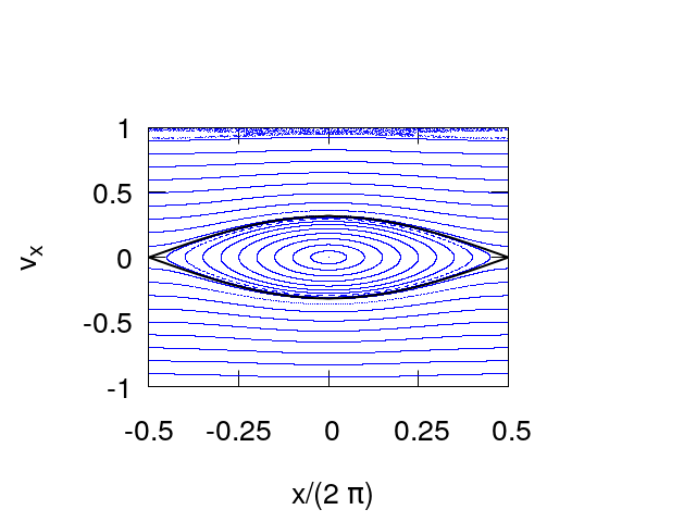
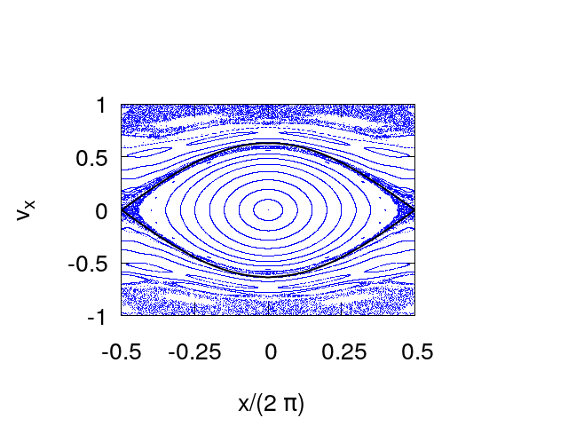
For a corrugated waveguide the phase plots of CLn(𝐱,ϵ)subscript𝐶𝐿𝑛𝐱italic-ϵC_{L\,n}({\bf x},\epsilon) and CRn(𝐱,ϵ)subscript𝐶𝑅𝑛𝐱italic-ϵC_{R\,n}({\bf x},\epsilon) for fixed n𝑛n of are the same as the plot of ELnsubscript𝐸𝐿𝑛E_{L\,n} and ERnsubscript𝐸𝑅𝑛E_{R\,n} in a logarithmic scale shown in the figures 2 and 3 for the 2D wave guide and 4 to 7 for the 4D waveguide, up to the constant factor n1superscript𝑛1n^{-1}. The 2D ray reflection map for ϵ1much-less-thanitalic-ϵ1\epsilon\ll 1 is almost integrable and exhibits two distinct regions delimited by a separatrix which can be approximated by

vx=±2ϵcos(x2)subscript𝑣𝑥plus-or-minus2italic-ϵ𝑥2v_{x}=\pm 2\,\sqrt{\epsilon}\,\cos\left({{x\over 2}}\right) (39)

see figure 8.

Refer to caption
Refer to caption
Refer to caption
Figure 8: Phase space portraits of the 2D map with the separatrix, black line, given by equation (40), for different values of the corrugation amplitude. Top frame: ϵ=0.005italic-ϵ0.005\epsilon=0.005. Center frame: ϵ=0.025italic-ϵ0.025\epsilon=0.025. Bottom frame: ϵ=0.1italic-ϵ0.1\epsilon=0.1.

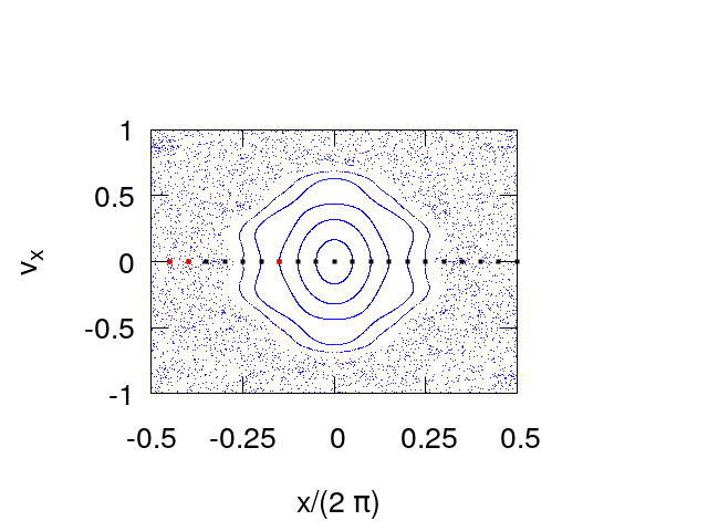
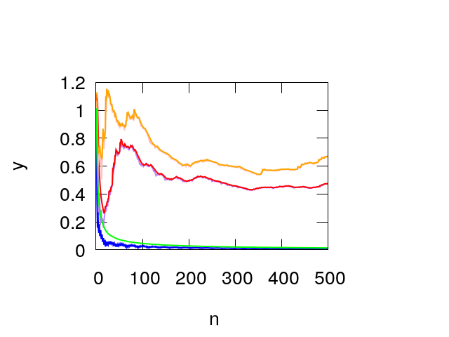
For ϵ0.1similar-toitalic-ϵ0.1\epsilon\sim 0.1 the separatrix becomes a thin stochastic layer, whose area grows by further increasing ϵitalic-ϵ\epsilon. We have compared the dependence on n𝑛n of the channel capacities CLn(𝐱,ϵ)subscript𝐶𝐿𝑛𝐱italic-ϵC_{L\,n}({\bf x},\epsilon) and CRn(𝐱,ϵ)subscript𝐶𝑅𝑛𝐱italic-ϵC_{R\,n}({\bf x},\epsilon) for one regular and two chaotic orbits, see figure 9. For the first orbit the channel capacity vanishes as n1lognsuperscript𝑛1𝑛n^{-1}\,\log n whereas for the last two chaotic orbits a finite limit is approached.
In order to appreciate how the limit for n𝑛n\to\infty is reached and the dependence on the corrugated amplitude we compute the following phase space averages

CLn(ϵ)=1μL()CLn(𝐱,ϵ)𝑑𝐱CRn(ϵ)=1μL()CRn(𝐱,ϵ)𝑑𝐱subscript𝐶𝐿𝑛italic-ϵ1subscript𝜇𝐿subscriptsubscript𝐶𝐿𝑛𝐱italic-ϵdifferential-d𝐱subscript𝐶𝑅𝑛italic-ϵ1subscript𝜇𝐿subscriptsubscript𝐶𝑅𝑛𝐱italic-ϵdifferential-d𝐱\begin{split}C_{L\,n}(\epsilon)&={1\over\mu_{L}({\cal E})}\,\int_{\cal E}\,C_{L\,n}({\bf x},\epsilon)\,d{\bf x}\\ C_{R\,n}(\epsilon)&={1\over\mu_{L}({\cal E})}\,\int_{\cal E}\,C_{R\,n}({\bf x},\epsilon)\,d{\bf x}\end{split} (40)

where {\cal E} denotes the phase space and μL()subscript𝜇𝐿\mu_{L}({\cal E}) its volume.
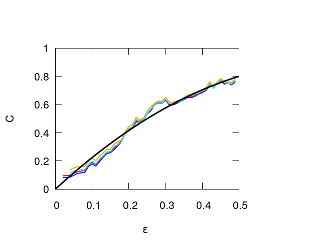
We have analyzed the dependence on the corrugation amplitude ϵitalic-ϵ\epsilon of the average channel capacities CLn(ϵ)subscript𝐶𝐿𝑛italic-ϵC_{L\,n}(\epsilon) and CRn(ϵ)subscript𝐶𝑅𝑛italic-ϵC_{R\,n}(\epsilon) for n=100𝑛100n=100 and n=200𝑛200n=200, see Figure 10. The channel capacity varies almost monotonically from 0 to 0.8 and corresponds to the phase space average of the maximum Lyapunov exponent, since for n=200𝑛200n=200 the asymptotic value appears to be reached. We have found the following quadratic fit with ϵitalic-ϵ\epsilon

C(ϵ)=2.4ϵ1.6ϵ20ϵ12formulae-sequence𝐶italic-ϵ2.4italic-ϵ1.6superscriptitalic-ϵ20italic-ϵ12C(\epsilon)=2.4\,\epsilon-1.6\,\epsilon^{2}\qquad\qquad 0\leq\epsilon\leq{1\over 2} (41)

A similar analysis can be performed for the 4D map by computing the phase space average with a Monte Carlo sampling rather than on a regular grid as for the 2D map.
Refer to caption
Refer to caption
Figure 9: Top panel: phase portrait of the 2D ray map for ϵ=0.25italic-ϵ0.25\epsilon=0.25. The blue and red dots correspond to the initial conditions. Bottom panel: dependence on n𝑛n of CnLsuperscriptsubscript𝐶𝑛𝐿C_{n}^{L} and CnRsuperscriptsubscript𝐶𝑛𝑅C_{n}^{R} for the chaotic orbits whose initial points are the first two red dots in left panel (LE pink, RE orange for the first orbit, LE purple, RE red for the second orbit) and the regular orbit whose initial point is the last red point (LE blue, RE green)
Refer to caption
Figure 10: Growth of the average channel capacities (on a regular grid of 400 points) with ϵitalic-ϵ\epsilon for two values of n𝑛n: CLnsubscript𝐶𝐿𝑛C_{L\,n} cyan for n=100𝑛100n=100, blue for n=200𝑛200n=200 and CRnsubscript𝐶𝑅𝑛C_{R\,n}, orange for n=100𝑛100n=100, red for n=200𝑛200n=200. The black line is a quadratic fit given by equation (41)

VIII Conclusions

We have analyzed the propagation of a ray on 2D and 3D waveguide, given by two parallel lines or planes, one of which has a periodic corrugation. In both cases the ray reflection maps on the uncorrugated line or plane are symplectic. The stability properties are relevant for the long term propagation of the rays. Indeed in the chaotic regions a diffusion occurs preventing the coherent propagation of a signal. We have analyzed the reflection maps using the short time indicators recently proposed: the Lyapunov error LE, and the reversibility errors RE and REM. The square of LE is the trace of the covariance matrix of the displacement, after n𝑛n iterations of the map, induced by a small initial random displacement. The square of RE is the trace of the covariance matrix of the displacement from the initial condition, when the map is iterated forward and backward n𝑛n times, adding at each step a small random displacement. Replacing the random displacement with the round off allows to define a modified reversibility error REM, which is similar to RE, though affected by large fluctuations due to the absence of averaging. In the 2D case a good qualitative agreement with the phase portrait is found. For a fixed number n𝑛n of reflection of the rays on the uncorrugated plane, all the indicators exhibit a similar behaviour with a power law growth for regular orbits and exponential growth for chaotic orbits. For small corrugations the motion is regular almost everywhere except in the neighborhood of the separatrix, occurring when the rays hit a minimum of the corrugated line or surface, and for rays propagating almost parallel to the waveguide
For the orbits of the 4D map, describing the ray dynamics of the 3D waveguide, LE and RE provide a satisfactory stability portrait, just as REM. A stability analysis in this case cannot be performed by looking at the projection of orbits on a 2D phase plane. Altogether these indicators quantify separately the effect of small initial displacements, additive noise and round off. The limited computational load and the simplicity of implementation of these indicators make them a convenient tool also for a parametric study of 2D and 3D waveguides. We have also considered the relation of our indicators with the channel capacity C𝐶C. Indeed the limit of n1logELnsuperscript𝑛1subscript𝐸𝐿𝑛n^{-1}\,\log E_{L\,n} and n1logERnsuperscript𝑛1subscript𝐸𝑅𝑛n^{-1}\,\log E_{R\,n} for n𝑛n\to\infty gives the maximum Lyapunov exponent which is isomorphic to the channel capacity. The dependence on n𝑛n for a given initial condition is consistent with theoretical estimates. The phase space average of the channel capacity is found to rise with the corrugation amplitude ϵitalic-ϵ\epsilon following a quadratic law.

IX Data Availability Statement

The data that support the findings of this study are openly available in https://github.com/gabrielegradoni/WaveguideStability.

Acknowledgements.
GG wishes to acknowledge the financial support of The Royal Society under the grant INF|||R2|||192066.

X Appendix A: tangent map for 2D waveguide

The equation which determines τ(x,v)𝜏𝑥𝑣\tau(x,v) is

G(x,v,τ)=1+ϵf(x+τv)τ1v2=0τx=GxGτ=ϵf1v2ϵvfτv=GvGτ=ϵτf+τv/1v21v2ϵvf𝐺𝑥𝑣𝜏1italic-ϵ𝑓𝑥𝜏𝑣𝜏1superscript𝑣20𝜏𝑥𝐺𝑥𝐺𝜏italic-ϵsuperscript𝑓1superscript𝑣2italic-ϵ𝑣superscript𝑓𝜏𝑣𝐺𝑣𝐺𝜏italic-ϵ𝜏superscript𝑓𝜏𝑣1superscript𝑣21superscript𝑣2italic-ϵ𝑣superscript𝑓\begin{split}G(x,v,\tau)&=1+\epsilon\,f(x+\tau v)-\tau\,\sqrt{1-v^{2}}=0\\ {\partial{\tau}\over\partial{x}}&=-{{\partial{G}\over\partial{x}}\over{\partial{G}\over\partial{\tau}}}={\epsilon\,f^{\prime}\over\sqrt{1-v^{2}}-\epsilon vf^{\prime}}\\ {\partial{\tau}\over\partial{v}}&=-{{\partial{G}\over\partial{v}}\over{\partial{G}\over\partial{\tau}}}={\epsilon\,\tau\,f^{\prime}+\tau\,v/\sqrt{1-v^{2}}\over\sqrt{1-v^{2}}-\epsilon vf^{\prime}}\end{split} (42)

Letting vx=cosθvsubscript𝑣𝑥𝑐𝑜𝑠𝜃𝑣v_{x}=cos\theta\equiv v and vz=sinθ1v2subscript𝑣𝑧𝜃1superscript𝑣2v_{z}=\sin\theta\equiv\sqrt{1-v^{2}} the recurrence which determines the symplectic map M=(x,v)𝑀𝑥𝑣M=(x,v) is given by

G(xn,vn,τ)=0vn+1=vn2ϵ2f2vnϵf1vn21+ϵ2f2xn+1=xn+τvn+τ1vn21vn+12vn+1𝐺subscript𝑥𝑛subscript𝑣𝑛𝜏0subscript𝑣𝑛1subscript𝑣𝑛2superscriptitalic-ϵ2superscriptsuperscript𝑓2subscript𝑣𝑛italic-ϵsuperscript𝑓1superscriptsubscript𝑣𝑛21superscriptitalic-ϵ2superscriptsuperscript𝑓2subscript𝑥𝑛1subscript𝑥𝑛𝜏subscript𝑣𝑛𝜏1superscriptsubscript𝑣𝑛21superscriptsubscript𝑣𝑛12subscript𝑣𝑛1\begin{split}&G(x_{n},v_{n},\tau)=0\\ \\ &v_{n+1}=v_{n}-2{\epsilon^{2}{f^{\prime}}^{2}\,v_{n}-\epsilon f^{\prime}\,\sqrt{1-v_{n}^{2}}\over 1+\epsilon^{2}{f^{\prime}}^{2}}\\ \\ &x_{n+1}=x_{n}+\tau v_{n}+\tau\,{\sqrt{1-v_{n}^{2}}\over\sqrt{1-v_{n+1}^{2}}}\,v_{n+1}\end{split} (43)

The tangent map is given by

vn+1xn=2ϵf′′(1+ϵ2f2)2[2ϵvnf+1vn2(1ϵ2f2)]××(1+vnτxn)vn+1vn=12ϵf1+ϵ2f2(ϵf+vn1vn2)++2ϵf′′(1+ϵ2f2)2[2ϵvnf+1vn2(1ϵ2f2)]××(τ+vnτvn)xn+1xn=1+(vn+vn+11vn21vn+12)τxn++τ1vn2(1vn+12)3/2vn+1xnxn+1vn=τ+(vn+vn+11vn21vn+12)τvn++τ1vn2(1vn+12)3/2vn+1vnτvn1vn2vn+11vn+12subscript𝑣𝑛1subscript𝑥𝑛2italic-ϵsuperscript𝑓′′superscript1superscriptitalic-ϵ2superscriptsuperscript𝑓22delimited-[]2italic-ϵsubscript𝑣𝑛superscript𝑓1superscriptsubscript𝑣𝑛21superscriptitalic-ϵ2superscriptsuperscript𝑓21subscript𝑣𝑛𝜏subscript𝑥𝑛subscript𝑣𝑛1subscript𝑣𝑛12italic-ϵsuperscript𝑓1superscriptitalic-ϵ2superscriptsuperscript𝑓2italic-ϵsuperscript𝑓subscript𝑣𝑛1superscriptsubscript𝑣𝑛22italic-ϵsuperscript𝑓′′superscript1superscriptitalic-ϵ2superscriptsuperscript𝑓22delimited-[]2italic-ϵsubscript𝑣𝑛superscript𝑓1superscriptsubscript𝑣𝑛21superscriptitalic-ϵ2superscriptsuperscript𝑓2𝜏subscript𝑣𝑛𝜏subscript𝑣𝑛subscript𝑥𝑛1subscript𝑥𝑛1subscript𝑣𝑛subscript𝑣𝑛11superscriptsubscript𝑣𝑛21subscriptsuperscript𝑣2𝑛1𝜏subscript𝑥𝑛𝜏1superscriptsubscript𝑣𝑛2superscript1superscriptsubscript𝑣𝑛1232subscript𝑣𝑛1subscript𝑥𝑛subscript𝑥𝑛1subscript𝑣𝑛𝜏subscript𝑣𝑛subscript𝑣𝑛11superscriptsubscript𝑣𝑛21subscriptsuperscript𝑣2𝑛1𝜏subscript𝑣𝑛𝜏1superscriptsubscript𝑣𝑛2superscript1superscriptsubscript𝑣𝑛1232subscript𝑣𝑛1subscript𝑣𝑛𝜏subscript𝑣𝑛1superscriptsubscript𝑣𝑛2subscript𝑣𝑛11superscriptsubscript𝑣𝑛12\begin{split}{\partial{v_{n+1}}\over\partial{x_{n}}}&={2\epsilon\,f^{\prime\prime}\over(1+\epsilon^{2}\,{f^{\prime}}^{2})^{2}}\,\left[{{-2\epsilon\,v_{n}\,f^{\prime}+\sqrt{1-v_{n}^{2}}\,(1-\epsilon^{2}{f^{\prime}}^{2})}}\right]\times\\ &\times\left({{1+v_{n}\,{\partial{\tau}\over\partial{x_{n}}}}}\right)\\ {\partial{v_{n+1}}\over\partial{v_{n}}}&=1-{2\,\epsilon\,f^{\prime}\over 1+\epsilon^{2}\,{f^{\prime}}^{2}}\,\left({{\epsilon\,f^{\prime}+{v_{n}\over\sqrt{1-v_{n}^{2}}}}}\right)+\\ &+{2\epsilon\,f^{\prime\prime}\over(1+\epsilon^{2}\,{f^{\prime}}^{2})^{2}}\left[{{-2\epsilon\,v_{n}\,f^{\prime}+\sqrt{1-v_{n}^{2}}\,(1-\epsilon^{2}{f^{\prime}}^{2})}}\right]\times\\ &\times\left({{\tau+v_{n}\,{\partial{\tau}\over\partial{v_{n}}}}}\right)\\ {\partial{x_{n+1}}\over\partial{x_{n}}}&=1+\left({{v_{n}\,+\,v_{n+1}{\sqrt{1-v_{n}^{2}}\over\sqrt{1-v^{2}_{n+1}}}}}\right)\,{\partial{\tau}\over\partial{x_{n}}}+\\ &+\tau{\sqrt{1-v_{n}^{2}}\over(1-v_{n+1}^{2})^{3/2}}\,{\partial{v_{n+1}}\over\partial{x_{n}}}\\ {\partial{x_{n+1}}\over\partial{v_{n}}}&=\tau+\left({{v_{n}\,+\,v_{n+1}{\sqrt{1-v_{n}^{2}}\over\sqrt{1-v^{2}_{n+1}}}}}\right)\,{\partial{\tau}\over\partial{v_{n}}}+\\ &+\tau{\sqrt{1-v_{n}^{2}}\over(1-v_{n+1}^{2})^{3/2}}\,{\partial{v_{n+1}}\over\partial{v_{n}}}-\\ &-\tau\,{v_{n}\over\sqrt{1-v_{n}^{2}}}\,{v_{n+1}\over\sqrt{1-v_{n+1}^{2}}}\end{split} (44)

In all the previous formulae f=f(xn+τvn)𝑓𝑓subscript𝑥𝑛𝜏subscript𝑣𝑛f=f(x_{n}+\tau\,v_{n}) with f=f(xn+τvn)superscript𝑓superscript𝑓subscript𝑥𝑛𝜏subscript𝑣𝑛f^{\prime}=f^{\prime}(x_{n}+\tau\,v_{n}) and f′′=f′′(xn+τvn)superscript𝑓′′superscript𝑓′′subscript𝑥𝑛𝜏subscript𝑣𝑛f^{\prime\prime}=f^{\prime\prime}(x_{n}+\tau\,v_{n}).
In order to check the limit ϵ0italic-ϵ0\epsilon\to 0 we recall that the map is given by

τ1vn2=1vn+1=vnxn+1=xn+2vn1vn2formulae-sequence𝜏1superscriptsubscript𝑣𝑛21subscript𝑣𝑛1subscript𝑣𝑛subscript𝑥𝑛1subscript𝑥𝑛2subscript𝑣𝑛1superscriptsubscript𝑣𝑛2\begin{split}\tau\,\sqrt{1-v_{n}^{2}}&=1\qquad\quad v_{n+1}=v_{n}\\ x_{n+1}&=x_{n}+2{v_{n}\over\sqrt{1-v_{n}^{2}}}\end{split} (45)

In this case the tangent map is given by

xn+1xn=1xn+1vn=2(1vn2)3/2vn+1xn=0vn+1vn=1subscript𝑥𝑛1subscript𝑥𝑛1subscript𝑥𝑛1subscript𝑣𝑛2superscript1superscriptsubscript𝑣𝑛232subscript𝑣𝑛1subscript𝑥𝑛0subscript𝑣𝑛1subscript𝑣𝑛1\begin{split}{\partial{x_{n+1}}\over\partial{x_{n}}}&=1\\ {\partial{x_{n+1}}\over\partial{v_{n}}}&={2\over(1-v_{n}^{2})^{3/2}}\\ {\partial{v_{n+1}}\over\partial{x_{n}}}&=0\\ {\partial{v_{n+1}}\over\partial{v_{n}}}&=1\end{split} (46)

In our example we choose f(x)𝑓𝑥f(x) periodic of period 2π2𝜋2\pi and scale the coordinates according to x=2πx𝑥2𝜋superscript𝑥x=2\pi\,x^{\prime} so that the new tangent map is given by

xn+1xn=xn+1xnxn+1vn=12πxn+1vnvn+1xn=2πvn+1xnsubscriptsuperscript𝑥𝑛1subscriptsuperscript𝑥𝑛subscript𝑥𝑛1subscript𝑥𝑛subscriptsuperscript𝑥𝑛1subscript𝑣𝑛12𝜋subscript𝑥𝑛1subscript𝑣𝑛subscript𝑣𝑛1subscriptsuperscript𝑥𝑛2𝜋subscript𝑣𝑛1subscript𝑥𝑛\begin{split}{\partial{x^{\prime}_{n+1}}\over\partial{x^{\prime}_{n}}}&={\partial{x_{n+1}}\over\partial{x_{n}}}\\ {\partial{x^{\prime}_{n+1}}\over\partial{v_{n}}}&={1\over 2\pi}\,{\partial{x_{n+1}}\over\partial{v_{n}}}\\ {\partial{v_{n+1}}\over\partial{x^{\prime}_{n}}}&=2\pi\,{\partial{v_{n+1}}\over\partial{x_{n}}}\end{split} (47)

XI Appendix B. The 3D wave-guide

The equation for the corrugates waveguide is given by equation (12) where f(x,y)𝑓𝑥𝑦f(x,y) is a periodic function. The normal vector ν𝜈\bf{\nu} and the tangent vectors τ𝐱,τ𝐲subscript𝜏𝐱subscript𝜏𝐲\bf{\tau}_{x},\,\bf{\tau}_{y} are given by

ν(𝐱,𝐲)=(ϵfx,ϵfy,1)T1+ϵ2(fx2+fy2)τ𝐱=(1, 0,ϵfx)T1+ϵ2fx2τ𝐱=(0,1,ϵfy)T1+ϵ2fy2𝜈𝐱𝐲superscriptitalic-ϵsubscript𝑓𝑥italic-ϵsubscript𝑓𝑦1𝑇1superscriptitalic-ϵ2subscriptsuperscript𝑓2𝑥subscriptsuperscript𝑓2𝑦subscript𝜏𝐱superscript1 0italic-ϵsubscript𝑓𝑥𝑇1superscriptitalic-ϵ2subscriptsuperscript𝑓2𝑥subscript𝜏𝐱superscript01italic-ϵsubscript𝑓𝑦𝑇1superscriptitalic-ϵ2subscriptsuperscript𝑓2𝑦\begin{split}\bf{\nu}(x,y)&={(\epsilon\,f_{x},\,\epsilon\,f_{y},\,-1)^{T}\over\sqrt{1+\epsilon^{2}(f^{2}_{x}+f^{2}_{y})}}\\ \bf{\tau}_{x}&={(1,\,0,\,\epsilon f_{x})^{T}\over\sqrt{1+\epsilon^{2}\,f^{2}_{x}}}\\ \bf{\tau}_{x}&={(0,1,\,\epsilon f_{y})^{T}\over\sqrt{1+\epsilon^{2}\,f^{2}_{y}}}\end{split} (48)

where fxf/xsubscript𝑓𝑥𝑓𝑥f_{x}\equiv\partial f/\partial x and fyf/ysubscript𝑓𝑦𝑓𝑦f_{y}\equiv\partial f/\partial y. For an analogy with the 2D case we might introduce the curvilinear abscissas sx,sysubscript𝑠𝑥subscript𝑠𝑦s_{x},s_{y} on the lines on the corrugated plane having y𝑦y fixed and x𝑥x fixed respectively

sx(x,y)=0x1+ϵ2fx2(x,y)𝑑xsy(x,y)=0y1+ϵ2fy2(x,y)𝑑ysubscript𝑠𝑥𝑥𝑦superscriptsubscript0𝑥1superscriptitalic-ϵ2superscriptsubscript𝑓𝑥2superscript𝑥𝑦differential-dsuperscript𝑥subscript𝑠𝑦𝑥𝑦superscriptsubscript0𝑦1superscriptitalic-ϵ2superscriptsubscript𝑓𝑦2𝑥superscript𝑦differential-dsuperscript𝑦\begin{split}s_{x}(x,y)&=\int_{0}^{x}\,\sqrt{1+\epsilon^{2}\,f_{x}^{2}(x^{\prime},y)}\,dx^{\prime}\\ s_{y}(x,y)&=\int_{0}^{y}\,\sqrt{1+\epsilon^{2}\,f_{y}^{2}(x,y^{\prime})}\,dy^{\prime}\end{split} (49)

so that, keeping y fixed, dsx=1+ϵ2fx2(x,y)dx𝑑subscript𝑠𝑥1superscriptitalic-ϵ2superscriptsubscript𝑓𝑥2𝑥𝑦𝑑𝑥ds_{x}=\sqrt{1+\epsilon^{2}\,f_{x}^{2}(x,y)}\,dx and, keeping x fixed, dsy=1+ϵ2fx2(x,y)dy𝑑subscript𝑠𝑦1superscriptitalic-ϵ2superscriptsubscript𝑓𝑥2𝑥𝑦𝑑𝑦ds_{y}=\sqrt{1+\epsilon^{2}\,f_{x}^{2}(x,y)}\,dy. The transformation from (x,y)𝑥𝑦(x,y) to (sx,sy)subscript𝑠𝑥subscript𝑠𝑦(s_{x},s_{y}) is invertible. Letting P0=(x0,y0,0)subscript𝑃0subscript𝑥0subscript𝑦00P_{0}=(x_{0},y_{0},0) be a point on the plane and Q=(x,y,z(x,y))𝑄𝑥𝑦𝑧𝑥𝑦Q=(x,y,z(x,y)) a point on the corrugated plane and P1=(x1,y1,0)subscript𝑃1subscript𝑥1subscript𝑦10P_{1}=(x_{1},y_{1},0) a new point on the plane we consider a ray whose path is P0,Q,P1subscript𝑃0𝑄subscript𝑃1P_{0},Q,P_{1}. We denote with 𝐯0subscript𝐯0{\bf v}_{0} and 𝐯𝐯{\bf v} the velocity of the ray directed from P0subscript𝑃0P_{0} to Q𝑄Q and from Q𝑄Q to P1subscript𝑃1P_{1}. As for the 2D2𝐷2D case we keep P0subscript𝑃0P_{0} and P1subscript𝑃1P_{1} fixed letting Q𝑄Q vary and consider the ray path length H𝐻H which depends on Q𝑄Q

H(x,y)=h(x0,y0,x,y)+h(x1,y1,x,y)h(x0,y0,x,y)=(xx0)2+(yy0)2+(1+ϵf(x,y))2𝐻𝑥𝑦subscript𝑥0subscript𝑦0𝑥𝑦subscript𝑥1subscript𝑦1𝑥𝑦subscript𝑥0subscript𝑦0𝑥𝑦superscript𝑥subscript𝑥02superscript𝑦subscript𝑦02superscript1italic-ϵ𝑓𝑥𝑦2\begin{split}H(x,y)&=h(x_{0},y_{0},x,y)+h(x_{1},y_{1},x,y)\\ \\ h(x_{0},y_{0},x,y)&=\sqrt{(x-x_{0})^{2}+(y-y_{0})^{2}+(1+\epsilon f(x,y))^{2}}\end{split} (50)

The velocities 𝐯0subscript𝐯0{\bf v}_{0} and 𝐯𝐯{\bf v}, denoting for brevity h0h(x0,y0,x,y)subscript0subscript𝑥0subscript𝑦0𝑥𝑦h_{0}\equiv h(x_{0},y_{0},x,y) and h1h(x1,y1,x,y)subscript1subscript𝑥1subscript𝑦1𝑥𝑦h_{1}\equiv h(x_{1},y_{1},x,y), are given by

𝐯0=(xx0,yy0, 1+ϵf(x,y))Th(x0,y0,x,y)𝐯=(x1x0,y1y0, 1+ϵf(x,y))Th(x1,y1,x,y)subscript𝐯0superscript𝑥subscript𝑥0𝑦subscript𝑦01italic-ϵ𝑓𝑥𝑦𝑇subscript𝑥0subscript𝑦0𝑥𝑦𝐯superscriptsubscript𝑥1subscript𝑥0subscript𝑦1subscript𝑦01italic-ϵ𝑓𝑥𝑦𝑇subscript𝑥1subscript𝑦1𝑥𝑦\begin{split}{\bf v}_{0}&={(x-x_{0},\,y-y_{0},\,1+\epsilon f(x,y))\,^{T}\over h(x_{0},y_{0},x,y)}\\ {\bf v}&={(x_{1}-x_{0},\,y_{1}-y_{0},\,1+\epsilon f(x,y)\,)^{T}\over h(x_{1},y_{1},x,y)}\end{split} (51)

We first compute the derivatives of h0subscript0h_{0} and h1subscript1h_{1} with respect to x𝑥x and y𝑦y

xh0=xx0+(1+ϵf)ϵfxh0=𝐯0τx1+ϵ2fx2yh0=yy0+(1+ϵf)ϵfyh0=𝐯0τy1+ϵ2fy2xh1=xx1+(1+ϵf)ϵfxh1=𝐯τx1+ϵ2fx2yh1=yy1+(1+ϵf)ϵfyh1=𝐯τy1+ϵ2fy2𝑥subscript0𝑥subscript𝑥01italic-ϵ𝑓italic-ϵsubscript𝑓𝑥subscript0subscript𝐯0subscript𝜏𝑥1superscriptitalic-ϵ2superscriptsubscript𝑓𝑥2𝑦subscript0𝑦subscript𝑦01italic-ϵ𝑓italic-ϵsubscript𝑓𝑦subscript0subscript𝐯0subscript𝜏𝑦1superscriptitalic-ϵ2superscriptsubscript𝑓𝑦2𝑥subscript1𝑥subscript𝑥11italic-ϵ𝑓italic-ϵsubscript𝑓𝑥subscript1𝐯subscript𝜏𝑥1superscriptitalic-ϵ2superscriptsubscript𝑓𝑥2𝑦subscript1𝑦subscript𝑦11italic-ϵ𝑓italic-ϵsubscript𝑓𝑦subscript1𝐯subscript𝜏𝑦1superscriptitalic-ϵ2superscriptsubscript𝑓𝑦2\begin{split}{\partial{}\over\partial{x}}\,h_{0}&={x-x_{0}+(1+\epsilon f)\,\epsilon\,f_{x}\over h_{0}}={\bf v}_{0}\cdot{\bf{\tau}}_{x}\,\sqrt{1+\epsilon^{2}\,f_{x}^{2}}\\ {\partial{}\over\partial{y}}\,h_{0}&={y-y_{0}+(1+\epsilon f)\,\epsilon\,f_{y}\over h_{0}}={\bf v}_{0}\cdot{\bf{\tau}}_{y}\,\sqrt{1+\epsilon^{2}\,f_{y}^{2}}\\ \\ {\partial{}\over\partial{x}}\,h_{1}&={x-x_{1}+(1+\epsilon f)\,\epsilon\,f_{x}\over h_{1}}=-{\bf v}\cdot{\bf{\tau}}_{x}\,\sqrt{1+\epsilon^{2}\,f_{x}^{2}}\\ {\partial{}\over\partial{y}}\,h_{1}&={y-y_{1}+(1+\epsilon f)\,\epsilon\,f_{y}\over h_{1}}=-{\bf v}\cdot{\bf{\tau}}_{y}\,\sqrt{1+\epsilon^{2}\,f_{y}^{2}}\end{split} (52)

Choosing h0subscript0h_{0} and h1subscript1h_{1} a functions of sx,sysubscript𝑠𝑥subscript𝑠𝑦s_{x},s_{y} rather than x,y𝑥𝑦x,y one has h0/sα=𝐯0ταsubscript0subscript𝑠𝛼subscript𝐯0subscript𝜏𝛼\partial{h_{0}}/\partial s_{\alpha}={\bf v}_{0}\cdot\bf{\tau}_{\alpha} and and h1/sα=𝐯ταsubscript1subscript𝑠𝛼𝐯subscript𝜏𝛼\partial{h_{1}}/\partial s_{\alpha}=-{\bf v}\cdot\bf{\tau}_{\alpha} for α=x,y𝛼𝑥𝑦\alpha=x,y. The function H𝐻H is stationary when 𝐯0τ𝐱=𝐯𝟎τ𝐱subscript𝐯0subscript𝜏𝐱subscript𝐯0subscript𝜏𝐱{\bf v}_{0}\cdot\bf{\tau}_{x}={\bf v}_{0}\cdot\bf{\tau}_{x} and 𝐯0τ𝐲=𝐯𝟎τ𝐲subscript𝐯0subscript𝜏𝐲subscript𝐯0subscript𝜏𝐲{\bf v}_{0}\cdot\bf{\tau}_{y}={\bf v}_{0}\cdot\bf{\tau}_{y} namely when the projection on the tangent plane of the incoming and outgoing ray velocities are equal. This corresponds to the reflection condition since the normal components of 𝐯0subscript𝐯0{\bf v}_{0} and 𝐯𝐯{\bf v} are opposite. The derivatives with respect to x0,y0subscript𝑥0subscript𝑦0x_{0},y_{0} and x1,y1subscript𝑥1subscript𝑦1x_{1},y_{1} are given by

h0x0=x0xh0=vx 0h0y0=y0yh0=vy 0h1x1=x1xh1=vx 1h1y1h1=y1yh1=vy 1formulae-sequencesubscript0subscript𝑥0subscript𝑥0𝑥subscript0subscript𝑣𝑥 0subscript0subscript𝑦0subscript𝑦0𝑦subscript0subscript𝑣𝑦 0subscript1subscript𝑥1subscript𝑥1𝑥subscript1subscript𝑣𝑥1subscript1subscript𝑦1subscript1subscript𝑦1𝑦subscript1subscript𝑣𝑦1\begin{split}{\partial{h_{0}}\over\partial{x_{0}}}\,&={x_{0}-x\over h_{0}}=-v_{x\,0}\qquad{\partial{h_{0}}\over\partial{y_{0}}}\,={y_{0}-y\over h_{0}}=-v_{y\,0}\\ \\ {\partial{h_{1}}\over\partial{x_{1}}}\,&={x_{1}-x\over h_{1}}=v_{x\,1}\qquad\quad{\partial{h_{1}}\over\partial{y_{1}}}\,h_{1}={y_{1}-y\over h_{1}}=-v_{y\,1}\end{split} (53)

Finally letting (x,y)subscript𝑥subscript𝑦(x_{*},y_{*}) the point where H𝐻H is stationary and which depends on end points (x0,y0)subscript𝑥0subscript𝑦0(x_{0},y_{0}) and (x1,y1)subscript𝑥1subscript𝑦1(x_{1},y_{1}) we introduce the function F𝐹F defined as the value of H𝐻H evaluated at the stationary point and compute its differential

F(x0,y0,x1,y1)=h(x0,y0,x,y)+h(x1,y1,x,y)dF=vx 0dx0vy 0dy0+vx 1dx1+vy 1dy1𝐹subscript𝑥0subscript𝑦0subscript𝑥1subscript𝑦1subscript𝑥0subscript𝑦0subscript𝑥subscript𝑦subscript𝑥1subscript𝑦1subscript𝑥subscript𝑦𝑑𝐹subscript𝑣𝑥 0𝑑subscript𝑥0subscript𝑣𝑦 0𝑑subscript𝑦0subscript𝑣𝑥1𝑑subscript𝑥1subscript𝑣𝑦1𝑑subscript𝑦1\begin{split}&F(x_{0},y_{0},x_{1},y_{1})=h(x_{0},y_{0},\,x_{*},y_{*})+h(x_{1},y_{1},\,x_{*},y_{*})\\ \\ &dF=-v_{x\,0}\,dx_{0}-v_{y\,0}\,dy_{0}+v_{x\,1}\,dx_{1}+v_{y\,1}\,dy_{1}\end{split} (54)

As a consequence F𝐹F is the generating function of a canonical transformation M𝑀M which maps (x0,vx 0,y0,vy 0)subscript𝑥0subscript𝑣𝑥 0subscript𝑦0subscript𝑣𝑦 0(x_{0},v_{x\,0},y_{0},v_{y\,0}) into (x1,vx 1,y1,vy 1)subscript𝑥1subscript𝑣𝑥1subscript𝑦1subscript𝑣𝑦1(x_{1},\,v_{x\,1},y_{1},v_{y\,1}). Denoting with 𝐱n=(xn,vxn,yn,vyn)Tsubscript𝐱𝑛superscriptsubscript𝑥𝑛subscript𝑣𝑥𝑛subscript𝑦𝑛subscript𝑣𝑦𝑛𝑇{\bf x}_{n}=(x_{n},v_{x\,n},y_{n},v_{y\,n})^{T} the phase space point reached after n𝑛n iterations of the symplectic map M𝑀M , the recurrence from 𝐱nsubscript𝐱𝑛{\bf x}_{n} to 𝐱n+1subscript𝐱𝑛1{\bf x}_{n+1} is obtained first by computing the transit time τ𝜏\tau from Pn=(xn,yn)subscript𝑃𝑛subscript𝑥𝑛subscript𝑦𝑛P_{n}=(x_{n},y_{n}) to the point Q=(x,y)𝑄subscript𝑥subscript𝑦Q=(x_{*},y_{*}) on the corrugated surface. Then we notice that the horizontal plane projections of the velocities 𝐯=𝐯n2ν(𝐯𝐧ν)subscript𝐯subscript𝐯𝑛2𝜈subscript𝐯𝐧𝜈{\bf v}_{*}={\bf v}_{n}-2\bf{\nu}({\bf v}_{n}\cdot\bf{\nu}) and 𝐯n+1subscript𝐯𝑛1{\bf v}_{n+1} of the ray reflected at Q𝑄Q and Pn+1=(xn+1,yn+1)subscript𝑃𝑛1subscript𝑥𝑛1subscript𝑦𝑛1P_{n+1}=(x_{n+1},y_{n+1}) are equal. Finally we determine the displacement from Pnsubscript𝑃𝑛P_{n} to Pn+1subscript𝑃𝑛1P_{n+1}. The equations defining the recurrence from 𝐱nsubscript𝐱𝑛{\bf x}_{n} to 𝐱n+1subscript𝐱𝑛1{\bf x}_{n+1} are given by (14).

References

  • (1) A. Bazzani, P. Freguglia, and G. Turchetti, Hamiltonian Analytical Optics and Simulations of Betatronic Motion by Optical Devices, in Nonlinear Dynamics and Collective Effects in Particle Beam Physics, World Scientific, pp. 23-46, (2019).
  • (2) L.A.Bunimovich On the Ergodic Properties of Nowhere Dispersing Billiards, Commun Math Phys. 65 (3), 295-312, (1979).
  • (3) J. Redmond, S. Tabachnikov Introducing symplectic billiards
    https://www.math.psu.edu/tabachni/prints/Notes5.pdf
  • (4) S. Tabachnikov billards
    https://www.math.psu.edu/tabachni/Books/billiardsbook.pdf
  • (5) S. Woo Park An introduction to dynamical billiards
    https://math.uchicago.edu/ may/REU2014/REUPapers/Park.pdf
  • (6) D. Holm and G. Kovacic, Homoclinic chaos for ray optics in a fiber , Physica D 51, p. 177 (1991).
  • (7) S. S. Abdullaev and G. M. Zavlaskii, Classical nonlinear dynamics and chaos of rays in problems of wave propagation in inhomogeneous media, Usp. Fiz. Nauk. 161, p. 1 (1991).
  • (8) D. Douglas, Chaotic billiard lasers , Nature 465, p. 696 (2010).
  • (9) S. Creagh, Directional Emission from Weakly Eccentric Resonators, Phys. Rev. Lett. 98, p. 153901 (2007).
  • (10) G. Tanner, Dynamical energy analysis Determining wave energy distributions in vibro-acoustical structures in the high-frequency regime, Journal of Sound and Vibration 98, p. 153901 (2007).
  • (11) E. Leonel, D. da Costa and C. Dettmann, Scaling invariance for the escape of particles from a periodically corrugated waveguide, Physics Letters A 376, 421 (2012).
  • (12) J. de Oliveira, C. Dettmann, D. , da Costa and E.  Leonel, Scaling invariance of the diffusion coefficient in a family of two-dimensional Hamiltonian mappings,Phys. Rev. E 87, p. 062904, (2013).
  • (13) G. Gradoni, J.-H. Yeh, B. Xiao, T. Antonsen, S. Anlage and O. E., Predicting the statistics of wave transport through chaotic cavities by the random coupling model: A review and recent progress, Wave Motion 51, 606 (2014).
  • (14) G. Forte, F. Cecconi and A. Vulpiani, Transport and fluctuation-dissipation relations in asymptotic and preasymptotic diffusion across channels with variable section, Phys. Rev E 90, p. 062110, (2014). http://denali.phys.uniroma1.it/ cecconif/MyPapersPDF/gforte_PRE90.pdf
  • (15) F. Cecconi, V. Blakaj, G. Gradoni and A. Vulpiani, Diffusive transport in highly corrugated channels, Phys. Lett. A, 383, pp. 1084-1091, (2018).
  • (16) C.  Froeschlé and E.  Lega. On the Structure of Symplectic Mappings. The Fast Lyapunov Indicator: a Very Sensitive Tool. Celestial Mechanics and Dynamical Astronomy, 78, 167–195, 2000.
  • (17) C.  Froeschlé, M.  Guzzo and E.  Lega. Graphical Evolution of the Arnold Web: From Order to Chaos. Science, 289, 2108–2110, September 2000.
  • (18) C. Skokos. Alignment indices: a new, simple method for determining the ordered or chaotic nature of orbits. Journal of Physics A Mathematical General, 34, 10029–10043, 2001.
  • (19) C. Skokos The Lyapunov Characteristic Exponents and Their Computation,J. Souchay and R. Dvorak (eds.), Lecture Notes in Physics, Berlin Springer Verlag Vol. 790, March 2010.
  • (20) R. Barrio. Theory and Applications of the Orthogonal Fast Lyapunov Indicator (OFLI and OFLI2) Methods. Chaos Detection and Predictability, 915, 55–92, March 2016.
  • (21) P. M.  Cincotta and C.  Simó. Simple tools to study global dynamics in non-axisymmetric galactic potentials - I. A&AS, 147, 205–228, December 2000.
  • (22) P. M. Cincotta, C. M. Giordano and C. Simó, Phase space structure of multi-dimensional systems by means of the mean exponential growth factor of nearby orbits, Physica D Nonlinear Phenomena 182, 151 (August 2003).
  • (23) Z. Sandor, B .Erdi, A. Szell, B. Funk. The relative Lyapunov indicator: an efficient method of chaos detection, Celestial Mechanics and Dynamical Astronomy 90, p. 127-138, (2004). https://arxiv.org/pdf/1205.0875.pdf
  • (24) Ch. Skokos, T. Bountis, Ch. Antonopoulos. Geometrical properties of local dynamics in Hamiltonian systems: The Generalized Alignment Index (GALI) method, Physica D 231, p. 3054, (2007).
  • (25) Ch. Skokos, T. Manos. The smaller (SALI) and the generalized (GALI) alignment indices: Efficient methods of chaos detection, Chaos Detection and Predictability Springer Lecture Notes in Physics, Editors: Ch. Skokos, Charalampos. G.A. Gottwald, J. Laskar (Eds.). https://arxiv.org/pdf/1412.7401.pdf
  • (26) C. Voglis, G. Contopoulos. The relative Lyapunov indicator: an efficient method of chaos detection Phys. Rev. E Vol 57, 372-377 (1998)
  • (27) . C. Voglis, G. Contopoulos, C. Efthymiopoulos. Detection of ordered and chaotic motion using the dynamical spectra Celestial Mechanics and Dynamical Astronomy Vol 73, 211-220 (1999)
  • (28) N. P. Maffione, L. A. Darriba · P. M. Cincotta · C. M. Giordano, comparison of different indicators of chaos based on the deviation vectors. Application to symplectic mappings Celestial Mechanics and Dynamical Astronomy 111 (2011) https://arxiv.org/abs/1108.2196
  • (29) N. P. Maffione, L. A. Darriba · P. M. Cincotta · C. M. Giordano, Comparative study of variational chaos indicators and ODEs numerical integrators, International Journal of Bifurcation and Chaos World Scientific Publishing Company (2012) 22, 1230033 (2012)
  • (30) D. Ruelle, An inequality for the entropy of differential maps, Bol. Soc. Bras. Mat., 9, 83-87, (1978).
  • (31) J.  Laskar, C.  Froeschlé and A.  Celletti. The measure of chaos by the numerical analysis of the fundamental frequencies. application to the standard mapping. Physica D: Nonlinear Phenomena, 56, 253–269, 05 1992.
  • (32) L. Casetti, C. Clementi, and M. Pettini, Riemannian theory of Hamiltonian chaos and Lyapunov exponents, Phys. Rev. E 54, 5969-5984 (1996).
  • (33) M. Cerruti-Sola, G. Ciraolo, M. Franzosi, M. Pettini. Riemannian geometry of Hamiltonian chaos: hints for a general theory. Phys. Rev. E Stat. Nonlin. Soft Matter Phys. 78, 046205 (2008)
  • (34) G. Gottwald, I. Melbourne, Testing for chaos in deterministic systems with noise, Physica D: Nonlinear Phenomena 212, 100-110 (2005)
  • (35) F. Panichi, L. Ciotti and G. Turchetti, Fidelity and reversibility in the restricted three body problem, Communications in Nonlinear Science and Numerical Simulation 35, 53 (2015).
  • (36) F. Panichi, K. Goździewski and G. Turchetti, The reversibility error method (REM): a new, dynamical fast indicator for planetary dynamics, MNRAS 468, 469 (June 2017).
  • (37) F. Panichi and G. Turchetti, Fast indicators of orbital stability: a survey on Lyapunov and Reversibility errors INTECH, (2019) https://www.intechopen.com/online-first/fast-indicators-for-orbital-stability-a-survey-on-lyapunov-and-reversibility-errors
  • (38) G. Turchetti, F. Panichi and K.  Gozdziewski A complete set of fast Lyapunov and Reversibility invariant indicators. To be submitted
  • (39) D. Faranda, M. F. Mestre and G. Turchetti, Analysis of Round off Errors with Reversibility Test as a Dynamical Indicator, International Journal of Bifurcation and Chaos, 22, p. 1250215 (September 2012).
  • (40) G.  Turchetti, S.  Vaienti and F.  Zanlungo. Asymptotic distribution of global errors in the numerical computations of dynamical systems. Physica A Statistical Mechanics and its Applications, 389, 4994–5006, (November 2010).
  • (41) E.  Hairer, C.  Lubich and G.  Wanner. Geometric Numerical Integration: Structure-Preserving Algorithms for Ordinary Differential Equations; 2nd ed. Springer, Dordrecht, (2006).
  • (42) G.  Turchetti, F.  Panichi Birkhoff normal forms and stability indicators for betatronic motion Proceedings of the NOCE workshop, Arcidosso sept. 2017, S. Di Mitri, S. Chattopadhyay, M. Cornacchia Editors, World Scientific (2019)
  • (43) Oseledets, V. I. (1968). A multiplicative ergodic theorem. characteristic Ljapunov, exponents of dynamical systems. Trudy Moskovskogo Matematicheskogo Obshchestva, 19:179-210.
  • (44) G. Friedland and A. Metere (eds.),Isomorphism between Maximum Lyapunov Exponent and Shannon?s Channel Capacity, https://arxiv.org/pdf/1706.08638.pdf, January 2018.
  • (45) Tim Holliday, Andrea Goldsmith, Peter W Glynn Capacity of Finite State Channels Based on Lyapunov Exponents of Random Matrices September 2006IEEE Transactions on Information Theory 52(8):3509 - 3532 DOI: 10.1109/TIT.2006.878230 (2006)
  • (46) Tim Holliday, Peter Glynn, Andrea Goldsmith On Entropy and Lyapunov Exponents for Finite-State Channels http://www.yaroslavvb.com/papers/holliday-entropy.pdf
  • (47) J. M. Ebeid Relating information theoretic limits to the Lyapunov exponents of a dynamical system https://www.ideals.illinois.edu/bitstream/handle/2142/16882/Ebeid_Hani-James.pdf?sequence=1&isAllowed=y