Cloud-RAN functional split for an efficient fronthaul network
Abstract
The evolution of telecommunication network towards cloud-native environments enables flexible centralization of the base band processing of radio signals. There is however a trade-off between the centralization benefits and the fronthaul cost for carrying the radio data between distributed antennas and data processing centers, which host the virtual RAN functions. In this paper, we present a specific split solution for an efficient fronthaul, which enables reducing the consumed bandwidth while being compliant with advanced cooperative radio technologies (interference reduction and data rate improvements). The proposed split has been implemented on the basis of Open Air Interface code and shows important gains in the required fronthaul bandwidth as well as significant latency reduction in the processing of radio frames.
Keywords: Cloud RAN, C-RAN, functional split, 5G, NFV.
I Introduction
Virtualization techniques deeply modify the architecture of telecommunication networks, notably via Network Function Virtualization (NFV) [1, 2]. While network functions were so far bound to their hosting hardware, virtualization enables a full decoupling between functions and hardware. While this change applies to many network functions (mobile core network, firewalls, etc.), virtualization has a particularly strong impact on Radio Access Network (RAN) and especially Centralized-RAN (C-RAN).
The concept of C-RAN was introduced a few years ago to take benefit of the centralization of Base Band Unit (BBU) functions, for better radio and computing resource allocation, energy efficiency, cost-saving, etc [3]. Beyond resource efficiency C-RAN shall bring agility, flexibility and time-to-market acceleration of future network features, which can be implemented via software upgrades without implying hardware changes [4].
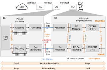
Today, C-RAN is a well established concept and has given rise to industrial implementations [5, 6]. An O-RAN alliance has been founded by operators to release open interfaces and to accelerate the delivery of products [7]. In general, a C-RAN is composed of three entities: Remote Unit (RU), Distributed Unit (DU) and Central Unit (CU). An RU hosts lower physical (LoPhy) functions while a DU executes higher physical (HiPhy) functions, MAC procedures and radio control tasks. A CU performs the higher RAN functions belonging to Radio Resource Control (RRC) and Packet Data Convergence Protocol (PDCP) protocols. The location of RUs is as close as possible to antennas, while DUs are in general located higher in the network in order to perform coordination of radio resource allocation and execute complex tasks (radio scheduling, channel coding) requesting intensive computing. A CU can be more centralized, say, at the PoP level, to manage, for instance, hand over so as to get rid of X2 interface between gNodeBs.
From a business perspective, C-RAN perfectly fits the emerging needs of TowerCos [4]. The owners of towers equipped or not with data centers, can host RU functions while DUs and CUs can be located in data centers in the backhaul or even higher in the network. For a network operator, it becomes possible to install DU/CUs on data centers and to maintain them with classical software upgrade/update tools. Elementary RAN functions are then executed in dedicated RUs.
To reach this goal, two critical aspects have to be addressed in the design of C-RAN: the fronthaul bandwidth and the distance between RUs and their controlling DUs (fronthaul size). The first point is deeply related to the functional split between HiPhy and LoPhy functions. A detailed description of different split options are given in the 3GPP specification [8]. Classical virtualized RAN (vRAN) was based on Option 8 that leads to huge fronthaul bandwidth capacities (about 10 Gbps per radio cell of 20 MHz). Meanwhile, ORAN alliance [7] [9] has more specifically considered Option 7.2. We shall consider this split as a reference in the following.
On the other hand, fronthaul size is constrained by the standardized Round Trip Time (RTT) budget which enables specifying response times and retransmission periods. In LTE the Hybrid Automatic Repeat-Request (HARQ) loop standardizes the round-trip latency to 3 milliseconds, then radio frames must to be processed within 1 and 2 milliseconds in the downlink and uplink directions, respectively, in order to meet the loop constraints. Thus, the distance between RUs and DUs directly depends on the computing platform and software optimization of RAN functions. In order to increase the fronthaul size, radio frames need to be processed as fast as possible. This calls for multi-core and multi-threading architectures. Remaining time after the base band processing is available for transmitting the radio information between the DU and RU at rate of 5 microseconds per kilometer (the light speed in optical fibers is taken equal to 200,000 km/s as an approximation).
In this paper, we pay special attention to the 7.3 split and moreover we introduce the uplink direction which has so far not been considered in the state of the art. This is motivated by the need to limit the fronthaul bandwidth. As a matter of fact, only hard bits are transmitted in the downlink; this is much more efficient than transmitting I/Q signals (e.g. splits 7.2) and naturally scales to goodput. Similarly, in the uplink the split consists of transmitting soft bits instead of radio symbols. The proposed split notably avoids compressing I/Q signals for the reduction of the required fronthaul capacity, in order to prevent additional signal degradation. Furthermore, by considering multi-threading techniques on a multi-core platform, it is possible to concentrate DUs several tens of kilometers from RUs.
This paper is organized as follows: In Section II, we review the various functional splits so far studied by standardization bodies as well as by Industry; this leads us to select Option 7.3. This split is further detailed in Section III. Testbed implementation guidelines and experimental results are presented in Section IV. Concluding remarks are finally presented in Section V.
II Rationale for the choice of a functional split
II-A Functional split options
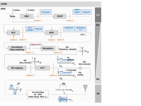
Several options for splitting RAN functions have been studied in the literature and notably by 3GPP [8], which proposes eight splits going from Option 1 (higher-layer split) to Option 8 (lower-layer split); see Figure 1. A fully centralized architecture (Option 8) has the benefit of cost reduction due to a fewer number of sites hosting RAN functions but requires high fronthaul capacity to transmit radio signals on fiber. The fronthaul capacity problem resides not only in the constant bit rate used by the legacy fronthaul protocol, namely Common Public Radio Interface (CPRI) [10], but also in the high redundancy present in the transmitted I/Q signals.
The assessment of the various splits has required huge research efforts; a survey of them is given in [11]. Particular attention has been paid to the intra-PHY functional splits due to the centralization advantages that they can achieve. Thus, most research efforts have turned to compression methods for reducing the required fronthaul capacity. Higher splits are less interesting since they do not exploit the centralization benefits and involve complex remote units.
The main features of the various splits are summarized in Table I, which clearly shows the trade-off between RU complexity and required fronthaul bandwidth. It is quite clear that less air interface optimization is possible from DU coordination when keeping RAN functions in the RU.
| Split | Advantage | Drawback |
|---|---|---|
| 8 | Lowest RU complexity, highest centralization | Very high Constant Bit Rate (CBR) in the fronthaul scaling with antennas |
| 7.1 | Low RU complexity | Fronthaul bandwidth scales with the number of antennas |
| 7.2 | Fronthaul bandwidth scales with used spectrum instead of number of antennas | High CBR in the fronthaul |
| 7.3DL | Low and load dependent bitrate on the fronthaul while keeping high centralization | No symmetry, 7.3 uplink is not considered by 3GPP |
| 6 | Centralized scheduling | The close relation between FEC and MAC disappears |
| 5 | Real-time functions are in the DU | Complex interface |
| 4 | Low fronthaul data rate | The close relation between RLC and MAC disappears |
| 3 | Favors reliability | Latency sensitive in some cases |
| 2 | Enables mobility coordination | Low centralization |
| 1 | User plane separation | Complex RU |
It is worth noting that the complexity of the RU is intrinsically related to the way of implementing LoPhy functions. For instance, by using FPGA for coding and Fourier transforms, the complexity of the RU clearly decreases as well as the associated energy consumption, at the expense of less agility with regard to software upgrades. Split 6 could thus be envisioned, but at the expense of losing the co-location of FEC and MAC (for real-time cooperative transmissions) and the joint processing of path diversity in the DU.
It turns out that 7.x family splits offer the best balance between RU complexity and inter-cell cooperation, though splits 7.1 and 7.2 can be greedy in terms bandwidth. We more thoroughly analyze 7.x splits in the next section.
II-B Analysis of 7.x splits
The assessment of intra-PHY options leads us to consider the fronthaul bandwidth as a critical Key Performance Indicator (KPI). In fact, the various 7.x options enable beam-forming, inter-cell coordination, low RU complexity, etc. and are future-proof as they allow the introduction of new features via software upgrades.
The required transmission bandwidth of 7.x splits is mainly determined by physical features such as:
-
•
The cell bandwidth and the number of sub-carriers (e.g., 1200 sub-carriers for a cell of 20 MHz).
-
•
The modulation order , number of bits per symbol (e.g. 4 bits for 16 QAM).
-
•
The number of MIMO layers (e.g., 2,4,8).
-
•
The number of antenna ports111Antenna ports are logical entities and do not correspond to physical antennas. Various antenna port signals can be transmitted on a single physical antenna. Similarly a single port signal can be spread across various antennas. .
-
•
The I/Q size , i.e, the required number of bits to code a constellation point (e.g., 32 bits for both in-phase and in-quadrature data).
Recent studies aim at reducing the I/Q size by compression methods, which involves floating point compressed representations, -law application, modulation compression schemes, and others (see for instance [12]). The ORAN initiative has notably included in the fronthaul ORAN-WG4.CUS.0-v0.2.0 [7] specification the possibility of transmitting I/Q data for both DL and UL (including user data and control channels) in compressed format. The specification is based on various compression and decompression techniques; however, selection algorithms and their performance evaluation are not yet available.
The main drawback when compressing I/Q signals is that they contain sensitive radio information elements, which are particularly critical for the RAN intelligence in the goal of reducing the noise impacts of the radio channel. Losing precision on the I/Q symbols is then highly risky for the user payload data rate and QoS of the RAN network.
II-B1 7.1 split
This split consists of transmitting I/Q symbols in the frequency domain. This option saves the overhead introduced by the frequency to time conversion 222The oversampling factor is given by , where is the number of FFT samples per symbol and is the number of sub-carriers per cell.. An experimental evaluation of low splits, namely Option 8 (referred to as IF5) and Option 7.1 (referred to as 4.5) is in [13]. Roughly, the fronthaul capacity (in bit/s, denoted for short as bps) required by the 7.1 split is mainly determined by the symbol size and the number for antenna ports as follows:
| (1) |
where is the symbol period given by the number of symbols carried in a time slot. For instance, when using normal cyclic prefix, LTE transmits symbols per slot of milliseconds ( milliseconds).
II-B2 7.2 split
Like 7.1 split, 7.2 split transmits I/Q signals in the frequency domain. However, signals coming from multiple antenna ports are combined; as a consequence, the required fronthaul capacity (in bps) is divided by , so that
| (2) |
II-B3 7.3 split
By keeping the demodulation/modulation function near to antennas, the fronthaul with the 7.3 split carries bits instead I/Q symbols. The required fronthaul capacity (in bps) is then divided by . In the downlink, the fronthaul capacity is determined by
| (3) |
Table II shows the required fronthaul capacity for the 7.x splits for a cell bandwidth of 10 MHz and 20 MHz, 2x2 MIMO (, 4 antenna ports () and QAM modulation (). Option 8 is indicated as a reference.
| Split | [Mbps] | [Mbps] |
|---|---|---|
| (10 MHz) | (20 MHz) | |
| Option 8 | ||
| Option 7.1 | ||
| Option 7.2 | ||
| Option 7.3 |
As observed in Table II, when using 7.1 split, the fronthaul capacity is halved when compared with the initial CPRI-based solution (Option 8). This however still leads to a large required fronthaul capacity. The 7.3 split is certainly the least bandwidth consuming. Nevertheless, 3GPP considers 7.3 only in the downlink direction. We introduce in Section III the corresponding 7.3 uplink split.
III 7.3 split implementation
III-A Principles
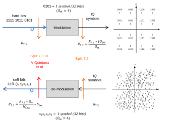
In this section, we describe the architecture associated with 7.3 split for both uplink and downlink directions. The proposed split centralizes the RAN upper layers including the channel encoding/decoding function higher in the network and distributes near to antennas (RU) the lower PHY functions, i.e., modulation/demodulation and OFDM signal generation/reception [14, 15]. See Figure 2 for an illustration.
Hard bits are sent in the downlink while soft bits (coded as real numbers) are transmitted in the uplink. Soft bits corresponds to Log-Likelihood Ratio (LLR), i.e., the log ratio of the probability that a particular bit is 1 to the probability that the same bit is 0 (logarithmic ratios are used for better precision). Soft bits need to be coded with a given precision referred to as bitwidth or size (e.g., 8 bits). Both hard and soft bits are encapsulated into UDP packets and transmitted on fiber links. The required fronthaul bandwidth in the uplink direction is given as by
| (4) |
where is the soft bit size.
III-B Benefits of 7.3 split
7.3 split prevents from transmitting the whole cell bandwidth and combines the various radio signals coming from multiple antennas but first of all it transmits bits instead of I/Q signals. This yields significant reduction in the required fronthaul capacity.
Beyond bandwidth, the fronthaul interface considered in the 7.3 split uses generic packet-based transport protocols instead of evolved vendor proprietary solutions, e.g., those based on CPRI.
III-C Transport and Protocol Architecture
We rely on UDP as basic transport mechanism between the RU and DU; we actually use the facilities of Linux UDP sockets. Sending sendSubFrame() and receiving receiveSubFrame() procedures are then used for both uplink and downlink directions. While the transmission function sends UDP chunks as soon as possible, the reception mechanism aims at collecting all UDP chunks belonging to a given subframe before to determine: (i) the entire subframe has been successfully received, (ii) the timeout is expired before subframe completion, (iii) chunks are jumbled, i.e. a chunk from the next subframe is arrived.
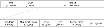
The transport header includes (see Figure 3):
-
•
Timestamp, subframe identifier (8 bytes).
-
•
Number of blocks belonging to the subframe (2 bytes).
-
•
Type which defines the content format (2 bytes).
-
•
Size333Theoretically, it must be less than bytes (from bytes for UDP limit, UDP header and IP header, respectively)., number of transmitted bytes including the split header (2 bytes).
-
•
Sender-Clock (8 bytes).
Regarding LTE control information, the DU notably transmits resource block position, power and Modulation and Coding Scheme (MCS) data with each data plane packet, which are used by the RU in low PHY functions. The RU in turn reports the Channel Quality Indicator (CQI) information obtained from the signal processing.
The DU sends signaling channels (e.g., DCI channel containing UE control information as HARQ feedback, scheduling information, frame organization, UE power control, UE paging requests, etc) to the RU as semantic data (number of DCI, position in the subframe, PHICH, PDCCH, …).
III-D Worst-case Analysis: I/Qs versus bits
For evaluating the gain that can be obtained when transmitting bits instead of I/Qs, we focus now on a worst-case analysis. Since the fronthaul bandwidth required by 7.3 split varies with the traffic load, we consider as a worst-case the peak data rate capacity of a cell of 100 MHz. Furthermore, the bandwidth saving achieved with 7.3 split strongly depends on the modulation order, we then consider the highest modulation schemes in Table III [8, 7]. In addition, we use 8 MIMO layers, I/Q size of 2x16 bits, 32 antenna ports, and soft bit size of 5 bits.
| Modulation | Option 7.3 | Option 7.2 | |
|---|---|---|---|
| DL | 256 QAM | 4.1 | 22.2 |
| UL | 64 QAM | 20.25 | 21.6 |
Option 7.3 evidences important downlink fronthaul reduction (even in a worst-case scenario). The gain in the uplink can be quickly improved when varying the modulation type. As shown in Figure 4, the trade-off between bits and I/Qs transmission is notably given by the modulation order.
Continuing with a worst-case approach (peak data rate), the overhead factor introduced when sending I/Q signals instead bits for various modulation orders is shown in Table IV. It turns out that 7.3 split is up to times better than 7.2 split, when using a QPSK modulation in the downlink direction. In the uplink the required fronthaul bandwidth is up to times better when using 7.3 (4 bits size) and QPSK modulation. In practice, the most commonly used modulation orders in the uplink are 16 QAM and QPSK. For instance, by using statistics from an operating mobile network, a 4G cell registers and usage of QPSK and 16 QAM modulation schemes, respectively. Only of traffic is modulated in 256 QAM.
| Mod. Scheme | Uplink ( | Uplink ( | Downlink | |
| 2 | QPSK | 2 | 4 | 16 |
| 4 | 16 QAM | 1 | 2 | 8 |
| 6 | 64 QAM | 0.7 | 1.3 | 5.3 |
| 8 | 256 QAM | 0.5 | 1 | 4 |
Beyond the modulation order, the uplink savings can take advantage of the size used for coding soft bits. Unlike I/Qs, soft bits size can be considerably reduced while avoiding signal degradation.
In the next section, we report experimental results from a testbed implementing the 7.3 split. The objective is to compare the theoretical estimations derived in the previous sections against experimental results.
IV Testbed experiments
IV-A Settings
In this section, we evaluate the performance of the proposed functional split (bidirectional 7.3 split) via a testbed implementation. The platform is notably composed of a distributed entity (placed near to antennas) and a centralized one (located in the backhaul network), which host the RU and the CU-DU, respectively. In this proof of concept, the RU and DU are linked by kilometer long optical fiber. The CU is co-localized with DU.
The RAN functions for the three RAN units, RU, DU, CU are based on Open Air Interface (OAI) [16] code and run on general purpose computers. The radio cell is configured in Frequency Division Duplex (FDD) mode and has a 10 MHz bandwidth. The Radio Frequency (RF) module is an USRP X310 card (tests have been also carried out when using an USRP B210). The testbed architecture and main features are presented in Figure 5.
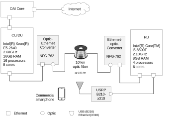
The main challenges when implementing intra-PHY splits are not only on the fronthaul interface but on the high performance computing required to meet the RAN real-time constraints. To reduce the processing time in the DU and thus to increase the distance between the RU and the DU, we implement in the DU the multi-threading model described in [14], which by means of parallel processing and adapted scheduling principles [17] achieve an important reduction in the runtime of the channel encoding and decoding (most resource consuming) functions. The thread-pool implementation is presented in [15]. The achieved RAN acceleration justifies the co-location of the CU/DU in the backhaul network (fronthaul size up 100 kilometers).
IV-B Fronthaul evaluation
In order to evaluate the required fronthaul capacity in the DU-RU interface, we vary the useful data rate (user traffic) from (when using ping, often 32 or 56 byte long) up to the peak data rate for a cell at 10 MHz. We concretely make use of a traffic generator, which sends UDP packets at a configurable rate to guarantee the chosen throughput regardless of random packet loss. These UDP packets are handled by the complete RAN protocol stack (PDCP, RLC, etc.) in both downlink (by the DU) and uplink (by the UE) directions.
The measured bandwidth in the fronthaul interface for the downlink (hard bits) and uplink (soft bits of 8 bits) is shown in Figures 6 and 7, respectively. The required fronthaul capacity is represented as a function of the traffic data rate.
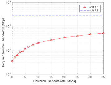
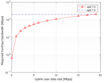
Performance results show important gains in the required fronthaul bandwidth with respect to other intra-PHY solutions (namely, 7.2 and 7.1 options of 3GPP [8]). In addition, it is observed that for both the uplink and downlink directions the required bandwidth varies with the useful data rate. Thus, fronthaul dimensioning can take advantage of variable bit rates by implementing statistical multiplexing and resource sharing mechanisms for important capital cost reduction.
Additionally, the split uses a packet based system for transmitting hard bits in the downlink direction and soft-bits in the uplink. Replacing the CPRI transmission over raw synchronous optical links, by packets over UDP/IP enables meshed connectivity between RAN components and allows effective adaptable and programmable networks [18].
V Conclusion
We have addressed in this paper the analysis and implementation of the 7.3 intra-PHY functional split in a C-RAN architecture and compared it with those of 7.x family, namely 7.1 and 7.2 splits, this latter being adopted by the ORAN alliance. We have particularly introduced the uplink 7.3 split in order to keep the centralization benefits while reducing the required fronthaul capacity (RU-DU interface). Achieved symmetry simplifies the 7.3 fronthaul interface and enables us to use UDP as basic transport mechanism. It opens the door to meshed connectivity and effective adaptable networks.
It turns out that the 7.3 split outperforms the other ones in terms of required fronthaul bandwidth and achievable distance between RU and DU, notably when considering suitable multi-threading of (de)coding functions.
The proposed split has been implemented on the basis of OAI open source code and tested in a proof of concept. The experimental results are in concordance with the theoretical estimations of the bit rates needed on the transmission link between the RU and DU. The next step is to integrate this split in the global RAN management architecture specified by ORAN, notably the RAN Intelligent Controller (RIC).
References
- [1] ETSI-NFV, “Network Functions Virtualisation, Architectural Framework,” Technical Report ETSI GS NFV 002 V1.1.1, Tech. Rep., 2013.
- [2] B. Han, V. Gopalakrishnan, L. Ji, and S. Lee, “Network function virtualization: Challenges and opportunities for innovations,” IEEE Communications Magazine, vol. 53, no. 2, pp. 90–97, 2015.
- [3] China Mobile Research Institute, “C-RAN, the road towards green RAN. White Paper,” 2011.
- [4] A. Reznik, L. M. C. Murillo, Y. Fang, W. Featherstone, M. Filippou, F. Fontes, F. Giust, Q. Huang, A. Li, C. Turyagyenda et al., “Cloud ran and mec: a perfect pairing,” ETSI MEC, no. 23, p. 25, 2018.
- [5] Wind (Intel), “vRAN: The Next Step in Network Transformation,” 2017, White Paper.
- [6] Intel, “Altiostar Delivers Virtual RAN Solution for MNOs,” 2019, solution Brief.
- [7] O-RAN Fronthaul Working Group, “Control, User and Synchronization Plane Specification,” O-RAN, Specification, 2019.
- [8] 3GPP, 3rd Generation Partnership Project, Study on new radio access technology Radio access architecture and interfaces, 3 2017, TR 38.801 V14.0.
- [9] O-RAN Alliance, “Operator Defined Next Generation RAN Architecture and Interfaces,” https://www.o-ran.org/, [Accessed February-2020].
- [10] J. Duan et al, “Performance analysis of several functional splits in C-RAN,” in Vehicular Technology Conference (VTC Spring), 2016 IEEE 83rd. IEEE, 2016, pp. 1–5.
- [11] L. M. Larsen, A. Checko, and H. L. Christiansen, “A survey of the functional splits proposed for 5g mobile crosshaul networks,” IEEE Communications Surveys & Tutorials, vol. 21, no. 1, pp. 146–172, 2018.
- [12] B. Guo, W. Cao, A. Tao, and D. Samardzija, “LTE/LTE-A signal compression on the CPRI interface,” Bell Labs Technical Journal, vol. 18, no. 2, pp. 117–133, 2013.
- [13] A. I. Salama and M. M. Elmesalawy, “Experimental OAI-based Testbed for Evaluating the Impact of Different Functional Splits on C-RAN Performance,” 2019 Novel Intelligent and Leading Emerging Sciences Conference (NILES), vol. 1, pp. 170–173, 2019.
- [14] V. Quintuna Rodriguez, “New Network / IT Command: Virtualized Function Performance for a Programmable Infrastructure,” https://hal.inria.fr/tel-01884431/document, [Accessed February-2020].
- [15] V. Quintuna Rodriguez and F. Guillemin, “Higher aggregation of gNodeBs in Cloud-RAN architectures via parallel computing,” in 22nd Conference on Innovation in Clouds, Internet and Networks and Workshops, ICIN, 2019, pp. 151–158.
- [16] OpenAirInterface, “5G software alliance for democratising wireless innovation,” https://www.openairinterface.org/, [Accessed February-2020].
- [17] V. Quintuna Rodriguez and F. Guillemin, “Cloud-RAN Modeling Based on Parallel Processing,” IEEE Journal on Selected Areas in Communications, vol. 36, no. 3, pp. 457–468, March 2018.
- [18] Fujitsu, “New Transport Network Architectures for 5G RAN,” White Paper, 2018.