Geometry Aware NMPC Scheme for Morphing Quadrotor Navigation in Restricted Entrances ††thanks: This work has been partially funded by the European Unions Horizon 2020 Research and Innovation Programme under the Grant Agreement No. 869379 illuMINEation. Corresponding author’s e-mail: andpap@ltu.se
Abstract
Geometry-morphing Micro Aerial Vehicles (MAVs) are gaining more and more attention lately, since their ability to modify their geometric morphology in-flight increases their versatility, while expanding their application range. In this novel research field, most of the works focus on the platform design and on the low-level control part for maintaining stability after the deformation. Nevertheless, another aspect of geometry morphing MAVs is the association of the deformation with respect to the shape and structure of the environment. In this article, we propose a novel Nonlinear Model Predictive Control (NMPC) structure that modifies the morphology of a quadrotor based on the environmental entrances geometrical shape. The proposed method considers restricted entrances as a constraint in the NMPC and modifies the arm configuration of the MAV to provide a collision free path from the initial position to the desired goal, while passing through the entrance. To the authors’ best knowledge, this work is the first to connect the in-flight morphology with the characteristics of environmental shapes. Multiple simulation results depict the performance and efficiency of the proposed scheme in scenarios where the quadrotor is commanded to pass through restricted areas.
I INTRODUCTION
Micro Aerial Vehicles (MAVs) are agile platforms with a variety of navigation capabilities including hovering over a target or aggressive maneuverability, allowing them to access remote and distance places, navigate through complex and harsh environments [1]. They are currently penetrating into the global economy with fast pace, invading markets from infrastructure to public security [2, 3], entertainment, search and rescue [4], mining [5] and forest industry [6]. A side effect of the vast interest to invest in MAVs is to constantly create new needs and market requirements, which eventually push the robotics community to look towards unexplored aspects of the technology. Currently, conventional MAVs with fixed frames lack the ability to adapt their shape based on the task requirements and environmental structure. For example, the common approach for a conventional platform, in cases where the path traverses through narrow gaps, would have been to miniaturize its size, sacrificing onboard payload. To this end, the concept of geometry-morphing aerial platforms is becoming relevant, trying to address the limitation of flight time and payload in cases where larger platforms with the desired payload can adaptively restructure their morphology in-flight to pass through restricted entrances.
Towards this direction, this article proposes a novel Nonlinear Model Predictive Control (NMPC) framework for collision-free navigation of a morphing MAV, through narrow entrances. The platform alters the position of the arms, based on the shape of the entrance, formulated as constraints in the control scheme. Another aspect of the proposed approach is that in case where the size of the entrance is below the allowed feasible, relative to the size of the platform, it does not allow the MAV to pass through that opening. Finally, the framework is able to provide different configurations, while maximizing the symmetry between arms when reforming for passing through the holes, a concept which assist the low-level controller to compensate for the arm configurations [7].
I-A Background & Motivation
The majority of the works in the literature of geometry-morphing aerial platforms focus on the design of the MAV and the low-level control scheme to maintain it’s stability when shape reformation occurs during the flight. The development of a foldable quadrotor with the ability to maintain stable flight, after changing its formation by rotating motion of each arm individually, has been presented in [7], while in [8] the authors study the effects of the overlapping among the propellers and the body frame. A foldable quadrotor design was presented in [9], where the platform was able to decrease its wide-span, by changing the orientation of its propellers based on an actuated elastic mechanism. Furthermore, in [10] a self-foldable quadrotor has been presented with a gear-based mechanism to control the contraction and expansion of the four arms simultaneously. This approach allowed for two possible configurations namely either fully expanded when the drone is deployed or fully contracted when the drone is on the ground. A passive foldable quadrotor has been presented in [11] that utilizes springs for altering its formation. The maneuverability of this design, while the drone is in its reduced form, was limited and the quadrotor can traverse only for a short time through narrow gaps. A sliding arm quadrotor has been presented in [12] from a modeling and control point of view, while few other works investigate MAVs with morphing [13, 14, 15, 16, 17, 18]. Besides transformable quadrotor platforms, other novel aerial vehicles that can alter their structure have been presented in the last years. DRAGON is a dual rotor multilink aerial robot that alters its formation with the use of multiple servos while flying [19] and being able to traverse through gaps.
Based on the related literature, there is a lack of scientific works that address the coupling of the morphing with the geometrical structure of the environment.
I-B Contributions
Based on the aforementioned state of the art, the main contribution of this article is threefold. The first contribution stems from incorporating the kinematic model of the MAV’s arm configuration in a novel NMPC framework. This formulation enables to reconfigure the in-flight geometric shape of the MAV, resulting in different arm configurations, in contrary to the related works which consider mainly four discrete types of configurations (X,Y,O,H).
The second contribution stems from the integration of the geometric constraints, which link the morphology of the platform and the restricted entrance in the NMPC formulation. The limited entrances are considered as nonlinear constraints, while based on the arm kinematics, the NMPC provides arm configuration to pass through the entrances. The overall framework provides a collision free path by reconfiguring the MAV arms, while considering MAV nonlinear dynamics and the geometric shape for a priori known restricted entrance, and only the desired set point is provided for the NMPC framework.
Finally, the efficiency of the proposed method is evaluated on multiple simulations, while it is demonstrated that without changing the arm configuration, the collision is unavoidable. In all cases the suggested novel framework is able to provide a collision free path.
I-C Outline
The rest of this article is structured as follows. In Section II the research problem is defined, while highlighting the challenges and limitations. Section III provides the non-linear model of a MAV, the kinematics of the folding mechanism, the theoretical control framework and the formulation of the optimization problem. The simulation specifics and results are provided in Section IV, while concluding remarks and future work are discussed in V.
II Problem Statement and Open Challenges
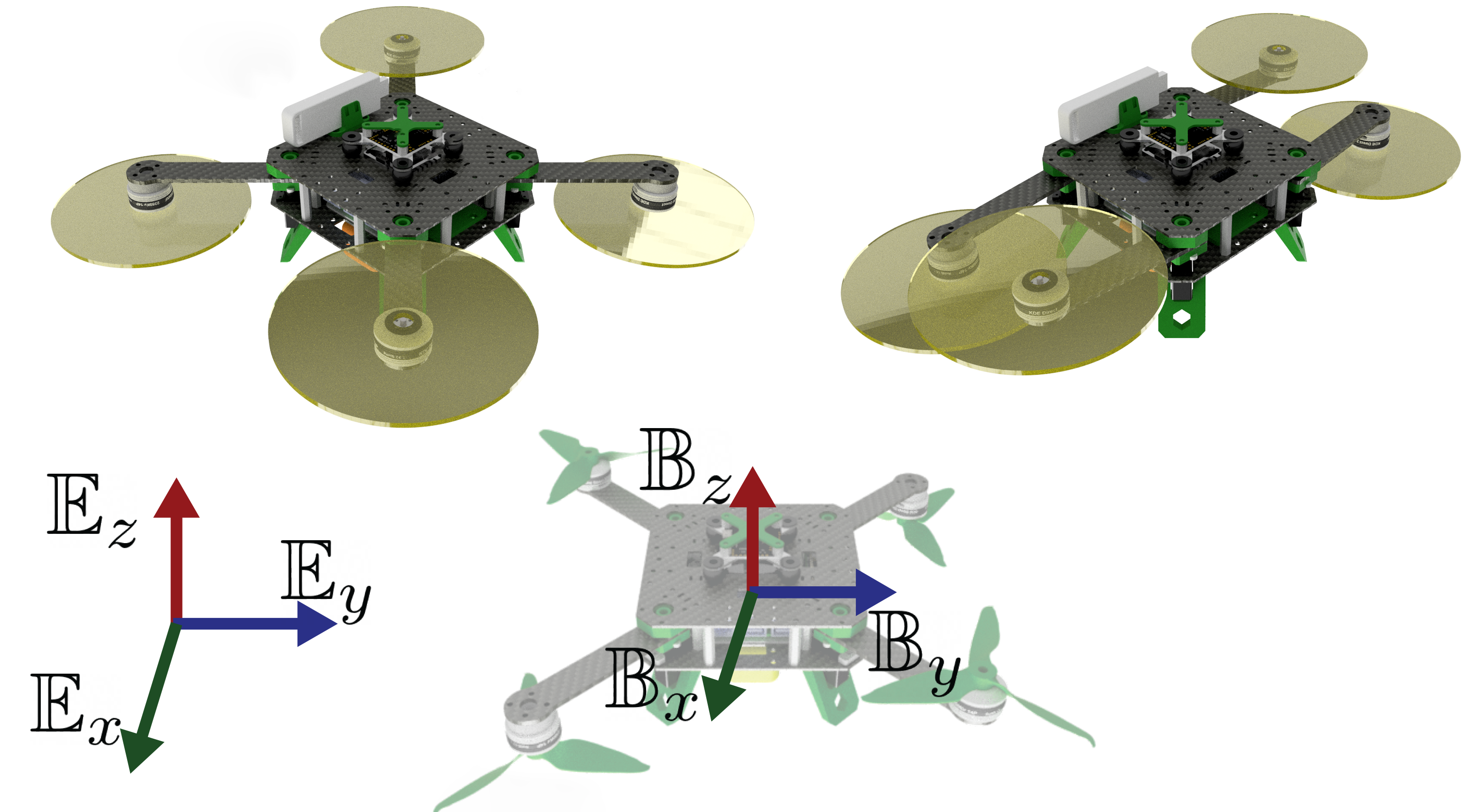
In Fig. 1 the conceptual design of a reconfigurable MAV is illustrated in isometric view for different formations. The arms of the quadrotor are connected on servos and they are able to rotate around the -axis. The geometry varies only related to the and -axis resulting in a planar-varying geometry as it is described in the sequel in Section III. To overcome possible collisions between the propellers at the extreme angles, the motors have been placed alternately upside down (Fig. 1).
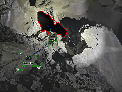
The MAVs can be considered as a scouting platform to gather information from challenging environments, such as underground mines [1] or search and rescue mission after natural catastrophes such as earthquakes. In most of these applications, the MAV should pass through narrow passages, as depicted in Figure 2 from underground mines. This article focus on the development of the NMPC framework that optimizes the size of a quadrotor by adapting its configuration based on the size of constrained entrances. The entrances’ location and size assumed to be known, thus the controller of the MAV provides the thrust, roll, pitch commands, and the arm configuration to navigate through the hole.
The ability of a reconfigurable quadrotor to alter its structure to different morphology can enhance specific characteristics, such us the size reduction and the sensor exposure of the platform at a cost of some other characteristics, such as nominal flight time and maneuverability. Out of all the different formations the specific design can take, the X morphology is the most balanced one thus is considered being the nominal configuration [7].
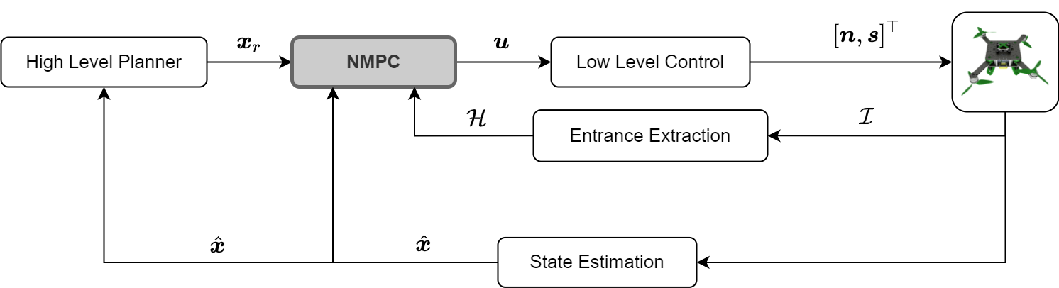
Figure 3 depicts the block diagram of the proposed structure, while the proposed framework of the NMPC is depicted with the gray highlighted block. The NMPC framework, based on the estimated states , the entrance information , and the reference waypoint provides thrust, roll, pitch and angles of the arms for the low level controller. The low level controller generates motor and servo commands for the MAV and respectively to track the desired attitude and morphology. This work focuses on the NMPC formulation, assuming that other state of the art entrance extraction methods (e.g. [20]) will provide .
III Nonlinear Model Predictive Control
III-A MAV Dynamics
The states of the nonlinear system of the six Degree of Freedom (DoF) MAV based on [21] are and modelled by (1):
| (1a) | ||||
| (1b) | ||||
| (1c) | ||||
| (1d) | ||||
where is the position vector and is the vector of linear velocities, are the roll and pitch angles respectively, is the rotation matrix about the and axis, is the mass-normalized thrust, is the gravitational acceleration, and are the normalized mass drag coefficients. The low-level control system is approximated by the first-order dynamics, driven by the reference pitch and roll angles and with gains of and time constants of and .
The notation in the 2D representation of the MAV in Fig. 4 is followed for the kinematics of the reconfigurable arms. Since the arms of the platform rotate only around the -axis, the kinematics of the arms varies only on the axis. The dimensions of the main body are denoting the width and length of the platform.
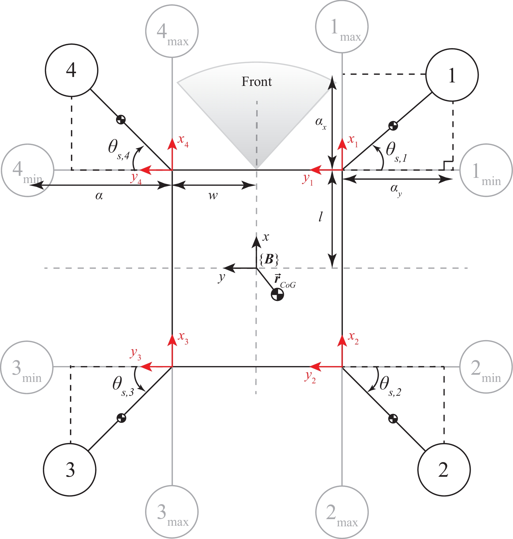
The arm length is denoted as and the rotation angle of the servo as for . The position of the arms’ final point varies based on the angle . The kinematics for the position vector of the arms are given in (2).
| (2b) | |||
| (2d) | |||
| (2f) | |||
| (2h) | |||
As an example, the X-configuration is achieved when all and the H-configuration which reduces the width of the MAV to its minimum is . The control action based on (1) and (2) is , where .
III-B Objective Function
The objective of the NMPC is to track a reference trajectory from a high-level path planner and to generate control actions . The controller can guarantee for a safety distance from a priori known obstacles, while generates angle commands for the servos of the arms to adapt the size of the MAV for specific type of obstacles. A low level controller (Fig. 3), depending on: 1) the present structural formation of the platform, 2) the control actions , and 3) the current heading of the MAV generates the motor commands and the servo commands for the platform to track the desired attitude and servo angles, a concept that has been also presented in [7, 16].
The NMPC approach solves a finite-horizon problem at every time instant with the prediction horizon of . The states and control actions are expressed by , and respectively for steps ahead from the current time step . For this purpose, the finite horizon cost function can be written as:
| (3) |
The objective function consists of four terms. The first term ensures the tracking of the desired states by minimizing the deviation from the current states. The second term, penalizes the deviation from the hover thrust with horizontal roll and pitch, and nominal X-configuration of the reconfigurable MAV, where is . The third term tracks the aggressiveness of the obtained control actions. This term will guarantee that when the platform is not near an obstacle, the MAV will keep its optimal formation. The last term imposes on the platform to pass through the middle of the obstacle , with the help of an adaptive weight which is enabled only when the MAV is in close proximity with an obstacle. In addition, the weights of the objective function’s terms are denoted as , , , and respectively, which they reflect to the relative importance of each term.
III-C Constraints
III-C1 Input Constraint
To bound the aggressive actuation, the following constraints are introduced for the angles and thrust rate of change , , and :
| (4a) | |||
| (4b) | |||
| (4c) | |||
| (4d) | |||
for . Where , , and denote the minimum and maximum rates. Additionally the inputs are constrained within specific boundaries in the following form:
| (5a) | |||
where and denote the minimum and maximum values the control actions can take.
III-C2 Restricted Entrances
There are different types of obstacles in the surrounding environment, nonetheless, all these types of obstacles can be categorized into three types: a) cylinder shape, b) polytope surface, and c) constrained entrance [21]. In this work the control framework focus on changing the formation of a morphing quadrotor to pass through limited passages, thus only constrained entrance obstacles are considered. When the MAV is outside the obstacle, the associated cost is forced to be zero and for this purpose, the function is utilized. With the proper selection of the expression, the constrained area is negative outside the obstacle and positive inside of it.
Cylindrical Entrances
A restricted entrance at with radius is defined in (6). The equation is defined in such way that is negative inside the radius of the obstacle and positive elsewhere. Thus, in order to guarantee this constraint the MAV should pass through the opening.
| (6) |
The area of the restricted entrance along the -axis is defined by (7a). While is the center of the obstacle on -axis the and define the extent of the passage for the left and right side of the entrance respectively. Depending on the entrance side either or will become positive.
| (7a) | ||||
| (7b) | ||||
Finally, the restricted entrance can be realized as a multiplication of the individual constraints (8). The expression results in positive values when the obstacle constraint is violated and zero elsewhere.
| (8) |
Cubic Entrances
This type of entrances are defined by their center coordinates and the length along -axis , width along -axis and height along -axis . Thus we can define and and similar for axis. The proper h-function can is defined in (9a) that describes the limits of the rectangular passage.
| (9a) | ||||
| (9b) | ||||
Finally, the rectangular restricted entrance constraint is defined in (10) with the help of (9a) and (7a).
| (10) |
where the is the logical AND operator.
III-C3 Geometric Constraints
The in (11) defines the limit from which the reconfigurable MAV need to adapt its size to match the properties of the restricted entrance. More specific is the safety distance from an obstacle that the platform does not consider its formation. The second part of the equation is the euclidean distance between the platform and the center of the entrance. Thus, the is positive when the platform is closer than the and zero elsewhere.
| (11) |
The width of the reconfigurable MAV—including the variable position of the arms following the definition from (2)—for the front and rear side of the platform can be defined as:
| (12a) | |||
| (12b) | |||
Based on (12) and with of the restricted entrance the constraint (13) is defined and it is positive when the width of the platform is larger than the width of the entrance. The is and in case of spherical and cubic entrances respectively.
| (13a) | |||
| (13b) | |||
Finally, in (14), the full constraint of the arms can be realized as a multiplication of the individual components.
| (14a) | |||
| (14b) | |||
III-D Embedded Optimization
Based on the previous definitions, the following optimization problem is defined:
| (15a) | ||||
| s.t. | (15b) | |||
| (15c) | ||||
| (15d) | ||||
The developed NMPC with passing through entrance constraints is solved by PANOC [22] to assure real-time performance of the control framework.
IV Results
IV-A Simulation Setup
Out of the numerous simulations, three representative cases are selected to prove the performance of the proposed control scheme. During the simulations, the eight states of the MAV considered measurable, while the position of the arms are computed based on the desired angles provided from the NMPC.
The parameters of the non-linear MAV model are the dimensions of the main body denoting the length, width and height respectively and the length of the arms is , the gravitational acceleration , the mass normalized drag coefficients and , and the time constants with gains . For visualization purposes we selected longer arms to emphasize the changes in the control scheme.
The prediction horizon has been set to 40 and the sampling time at . The roll and pitch angles are constrained within , while the angles change of rate is bounded between . The rotation of the arms is constrained in . The weights of the states are , while the control action weights are , and the weights for the input rate of change are . The weights for passing through the middle of the entrance are if the distance between the MAV and the center of the obstacle is and elsewhere. The for every case, since the obstacle is parallel with the -axis by definition, thus to navigate through the center of the obstacle the MAV should pass at and . The simulation trials were running on a single core to solve the optimization problem and they performed in a personal computer with an Intel(R) Core(TM) i7-8550U @ processor with of RAM. For all the simulation the mean computation time is and the max
IV-B Spherical Entrance Navigation
For the first simulation, the reconfigurable quadrotor passes through two narrow passages with different radii. Each time the glsnmpc provides the control actions to pass through the obstacle and to regulate the position of the arms to achieve the best balance between size reduction to avoid collision and maintain a morphology as close as possible to the X configuration. Fig. 5 illustrates the path that the reconfigurable MAV follows when entering and exiting from the two cylindrical obstacles.
The first entrance is located at with radius . The second entrance is located at with radius . The initial position of the platform is at and the two sequential goal positions are and respectively. The heading of the platform is set to look always towards to the obstacle and the safety distance between the obstacle and the platform is .
The top view of the MAV trajectory and spherical entrances is presented in Fig. 6. As it can be seen, the MAV reconfigure the arm positions to pass through the entrances.
In Fig. 7 presents the control actions of and the NMPC controller provides for the platform to navigate to the final destination. It can be observed that the control actions are smooth and there is no violation of the input constraints.
The top of Fig. 8 shows the time response of the euclidean distance between the two obstacles and the platform, while the bottom Fig. 8 shows the distance between the two front and two rear arms and in extend the width of the platform, as well as the radius of the obstacles. It can be noticed, when the platform approaches the entrance of the obstacles it reduces its size and as soon as it passes through the obstacles it returns to the initial X-configuration. More specific at the where the platform reaches the obstacle it has already adapt the size of the radius of the small obstacle. Approximately at the time instant of the reconfigurable MAV approaches the second entrance and it adapts its size to pass through the restricted entrance. It should be noted that the NMPC provides larger arm distance for the second entrance as it has slightly larger size compare to first entrance.
IV-C Impassable Entrance
For this case, the reconfigurable MAV is placed near an extremely narrow passage and it is desired to pass through it. The radius of the obstacle is smaller than the minimum possible size that the platform can adapt i.e. . In Fig. 9, three different starting points have been selected, located at , and and the goal point is located at . For all the starting points the NMPC succeeds to stop and avoid collision with the obstacle and as a result it cannot reach the final way-point. The safety distance between the obstacle and the platform is .
For this scenario, the controller identifies that it cannot pass through the entrance without violating the constraint (13). Since the distance between the obstacle and the MAV is the platform maintains the X-configuration (Fig. 10). The same behavior is observed independent of the starting point for all simulations, thus the distance between the arms and is the same for all the considered three cases.
IV-D Cubic Entrance
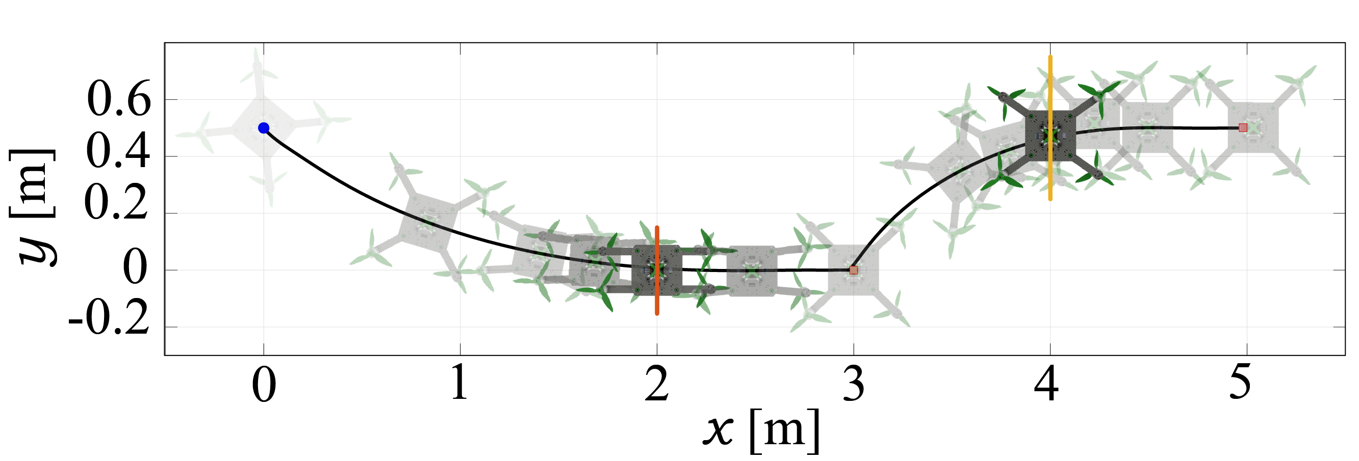
For the last presented case, the reconfigurable MAV passes through two narrow rectangular shaped entrances with different width. The NMPC provides the proper commands for the arms to optimize the size of the MAV to navigate through the opening. Fig. 11 illustrates the path that the MAV follow when entering and exiting the two cubic restricted entrances.
The center of the first rectangular opening is located at with dimensions . The second entrance is located at with dimensions . The initial position of the platform is at and the two sequential goal positions are at and respectively. The heading of the platform is set to look always forward to the obstacle and the safety distance between the obstacle and the platform is .
V Conclusion
This article proposed a novel NMPC framework for collision-free navigation of a morphing MAV, through restricted entrances. The reconfigurable MAV can alter the position of the arms to adapt its shape based on information about its environment. More specifically, the NMPC was able to provide the necessary control actions to navigate through narrow entrances adapting its size, while flying in two different types of entrances, namely a spherical and a cubic. When the size of the entrance was smaller than the the size of the platform, the MAV is not attempting to pass through the entrance. In all scenarios the proposed framework provided a collision free path for the MAV. Future work, will tackle the problem from an experimental point of view as well as to extent our methodology to more complex entrances with non-convex shapes.
References
- [1] S. S. Mansouri, C. Kanellakis, D. Kominiak, and G. Nikolakopoulos, “Deploying mavs for autonomous navigation in dark underground mine environments,” Robotics and Autonomous Systems, vol. 126, p. 103472, 2020.
- [2] S. S. Mansouri, C. Kanellakis, E. Fresk, D. Kominiak, and G. Nikolakopoulos, “Cooperative coverage path planning for visual inspection,” Control Engineering Practice, vol. 74, pp. 118–131, 2018.
- [3] A. Adaldo, S. S. Mansouri, C. Kanellakis, D. V. Dimarogonas, K. H. Johansson, and G. Nikolakopoulos, “Cooperative coverage for surveillance of 3d structures,” in 2017 IEEE/RSJ International Conference on Intelligent Robots and Systems (IROS). IEEE, 2017, pp. 1838–1845.
- [4] C. Sampedro, A. Rodriguez-Ramos, H. Bavle, A. Carrio, P. de la Puente, and P. Campoy, “A fully-autonomous aerial robot for search and rescue applications in indoor environments using learning-based techniques,” Journal of Intelligent & Robotic Systems, pp. 1–27, 2018.
- [5] S. S. Mansouri, C. Kanellakis, E. Fresk, B. Lindqvist, D. Kominiak, A. Koval, P. Sopasakis, and G. Nikolakopoulos, “Subterranean MAV navigation based on nonlinear MPC with collision avoidance constraints,” IFAC-PapersOnLine, 2020.
- [6] K. Steich, M. Kamel, P. Beardsley, M. K. Obrist, R. Siegwart, and T. Lachat, “Tree cavity inspection using aerial robots,” in 2016 IEEE/RSJ International Conference on Intelligent Robots and Systems (IROS). IEEE, 2016, pp. 4856–4862.
- [7] D. Falanga, K. Kleber, S. Mintchev, D. Floreano, and D. Scaramuzza, “The foldable drone: A morphing quadrotor that can squeeze and fly,” IEEE Robotics and Automation Letters, vol. 4, no. 2, pp. 209–216, 2018.
- [8] A. Fabris, K. Kleber, D. Falanga, and D. Scaramuzza, “Geometry-aware compensation scheme for morphing drones,” arXiv preprint arXiv:2003.03929, 2020.
- [9] V. Riviere, A. Manecy, and S. Viollet, “Agile robotic fliers: A morphing-based approach,” Soft robotics, vol. 5, no. 5, pp. 541–553, 2018.
- [10] T. Tuna, S. E. Ovur, E. Gokbel, and T. Kumbasar, “Design and development of folly: A self-foldable and self-deployable quadcopter,” Aerospace Science and Technology, vol. 100, p. 105807, 2020.
- [11] N. Bucki and M. W. Mueller, “Design and control of a passively morphing quadcopter,” in 2019 International Conference on Robotics and Automation (ICRA). IEEE, 2019, pp. 9116–9122.
- [12] R. Kumar, A. M. Deshpande, J. Z. Wells, and M. Kumar, “Flight control of sliding arm quadcopter with dynamic structural parameters,” arXiv preprint arXiv:2004.12920, 2020.
- [13] Y. Bai and S. Gururajan, “Evaluation of a baseline controller for autonomous “figure-8” flights of a morphing geometry quadcopter: Flight performance,” Drones, vol. 3, no. 3, p. 70, 2019.
- [14] S. Derrouaoui, Y. Bouzid, M. Guiatni, I. Dib, and N. Moudjari, “Design and modeling of unconventional quadrotors,” in 2020 28th Mediterranean Conference on Control and Automation (MED). IEEE, 2020, pp. 721–726.
- [15] A. Sakaguchi, T. Takimoto, and T. Ushio, “A novel quadcopter with a tilting frame using parallel link mechanism,” in 2019 International Conference on Unmanned Aircraft Systems (ICUAS). IEEE, 2019, pp. 674–683.
- [16] A. Papadimitriou and G. Nikolakopoulos, “Switching model predictive control for online structural reformations of a foldable quadrotor,” arXiv preprint arXiv:2008.08893, 2020.
- [17] N. Meiri and D. Zarrouk, “Flying star, a hybrid crawling and flying sprawl tuned robot,” in 2019 International Conference on Robotics and Automation (ICRA). IEEE, 2019, pp. 5302–5308.
- [18] J. Shu and P. Chirarattananon, “A quadrotor with an origami-inspired protective mechanism,” IEEE Robotics and Automation Letters, vol. 4, no. 4, pp. 3820–3827, 2019.
- [19] M. Zhao, T. Anzai, F. Shi, X. Chen, K. Okada, and M. Inaba, “Design, modeling, and control of an aerial robot dragon: A dual-rotor-embedded multilink robot with the ability of multi-degree-of-freedom aerial transformation,” IEEE Robotics and Automation Letters, vol. 3, no. 2, pp. 1176–1183, 2018.
- [20] N. J. Sanket, C. D. Singh, K. Ganguly, C. Fermüller, and Y. Aloimonos, “Gapflyt: Active vision based minimalist structure-less gap detection for quadrotor flight,” IEEE Robotics and Automation Letters, vol. 3, no. 4, pp. 2799–2806, 2018.
- [21] B. Lindqvist, S. S. Mansouri, and G. Nikolakopoulos, “Non-linear mpc based navigation for micro aerial vehicles in constrained environments,” in 2020 European Control Conference (ECC). IEEE, 2020, pp. 837–842.
- [22] A. S. Sathya, P. Sopasakis, R. Van Parys, A. Themelis, G. Pipeleers, and P. Patrinos, “Embedded nonlinear model predictive control for obstacle avoidance using panoc,” in Proceedings of the 2018 European Control Conference, 2018.