Reversible ratchet effects in a narrow superconducting ring
Abstract
We study the ratchet effect in a narrow pinning-free superconductive ring based on time-dependent Ginzburg-Landau (TDGL) equations. Voltage responses to external dc an ac currents at various magnetic fields are studied. Due to asymmetric barriers for flux penetration and flux exit in the ring-shaped superconductor, the critical current above which the flux-flow state is reached, as well as the critical current for the transition to the normal state, are different for the two directions of applied current. These effects cooperatively cause ratchet signal reversal at high magnetic fields, which has not been reported to date in a pinning-free system. The ratchet signal found here is larger than those induced by asymmetric pinning potentials. Our results also demonstrate the feasibility of using mesoscopic superconductors to employ superconducting diode effect in versatile superconducting devices.
pacs:
74.25.Wx, 74.25.Uv,74.78.Na, 74.40.GhI Introduction
In type-II superconductors, magnetic flux penetrates into the sample under the magnetic field above the lower critical field, forming quantized magnetic flux lines known as Abrikosov vortices. When applying a sufficiently large current, vortices are driven across the sample due to Lorentz force, resulting in finite voltage signals. If the vortex dynamics differs with respect to the polarity of applied current, the associated voltage would be different, producing the vortex ratchet effect. Vortex ratchet systems not only provide a convenient platform to investigate the fundamental vortex dynamics, but also are applicable in superconductive circuits. In that respect, manipulating vortices using ratchet systems has been demonstrated in many experiments lee1999reducing ; wambaugh1999superconducting ; olson2001collective ; villegas2003superconducting ; vlasko2017magnetic ; zhu2004controlling ; veshchunov2016optical . Ratchet effect can be employed to remove undesirable vortices trapped in superconductors, to thereby improve the performance of superconducting devices. Recently, the nonreciprocal charge transport has been observed in various superconductors with noncentrosymmetric or chiral structures qin2017superconductivity ; yasuda2019nonreciprocal ; wakatsuki2017nonreciprocal . More recently, the superconducting diode effect that has zero resistance for only one direction of the current has been realized in a noncentrosymmetric superlattice by stacking three kinds of superconducting elements ando2020observation , which may pave the way for potential applications in low dissipative electronic circuits.
Vortex ratchet systems are typically realized by introducing asymmetric pinning potentials in the superconducting samples to fine tune the vortex dynamics rouco2015geometrically ; zhu2003controllable ; adami2015onset ; reichhardt2015reversible ; reichhardt2016transverse ; reichhardt2017pinning . Pinning-free superconductors of special geometries could also serve as the vortex ratchet systems. In a superconducting sample with asymmetric edges, the vortex dynamics can be affected by intrinsic edge barriers. Recently, such kinds of pinning-free vortex ratchet superconducting systems have also attracted much attention ji2016vortex ; ji2017ratchet ; berdiyorov2012spatially ; hortensius2012critical ; schildermans2007voltage ; adami2013current ; vodolazov2005superconducting ; berdiyorov2010vortices . Ratchet systems without artificial pinning centers distinguish themselves with the ability to produce a stable and strong rectifying effect ji2016vortex ; ji2017ratchet . In practice, superconductors with specifically targeted asymmetric geometry have been widely used in experiments as single-photon detectors, parametric amplifiers and superconducting quantum interference devices(SQUIDs) halbertal2016nanoscale ; day2003broadband ; hortensius2012critical ; mittendorff2013ultrafast . On the other hand, superconducting nanowires and nanoribbons are the key components in these advanced superconducting circuits or devices. Low-dimensional superconducting structures provide unique properties and have been widely studied berdiyorov2012magnetoresistance ; berdiyorov2012large ; blatt1963shape ; PhysRevLett.61.2137 ; PhysRev.164.498 ; PhysRevB.1.1054 ; PhysRevLett.95.116805 ; kenawy2020electronically . To improve the performance and reliability of superconducting devices, it is crucial to understand the rich vortex dynamics in low-dimensional superconducting systems with specified geometries.
Although ratchet effects have been reported in many systems in the literature, ratchet signal reversal is seldomly observed. Systems with specially designed edges to date have been reported to give strong and stable ratchet signals without sign reversal ji2016vortex ; ji2017ratchet ; berdiyorov2012spatially ; hortensius2012critical ; schildermans2007voltage ; adami2013current ; vodolazov2005superconducting . On the other hand, the ratchet reversal in bulk or two-dimensional (2D) superconducting samples with asymmetric pinning arrays has been reported in both experiments and numerical simulations reichhardt2015reversible ; reichhardt2016transverse ; adami2015onset ; wu2015special , though these reversible ratchet signals strongly depended on the properties of the applied pinning potentials (such as density and strength of the pinning sites).
In this paper, by means of numerical simulations we reveal strong and stable reversible ratchet signals in a broad range of magnetic fields and external currents, in a pinning-free, narrow superconducting ring. We even find a superconducting-diode-like state, with vanishing resistance for only one current direction. The paper is organized as follows. In Sec. II, we introduce the time-dependent Ginzburg-Landau (TDGL) equations, which are used to simulate the condensate dynamics in the presence of external dc and ac currents at various magnetic fields. The main simulation results for ratchet effects generated under dc and ac currents are presented and analyzed in Sec. III and IV, respectively. The associated mechanism for the reversible ratchet signals is also described in detail. Additional videos for detailed visualization of the vortex motion are provided in the Supplemental Material Supplemental to help understand the vortex dynamics. Finally, conclusions are drawn in Sec. V.
II Numerical approach
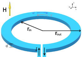
We use the TDGL theory to simulate a pinning-free superconducting ring. An oblique view of the system is shown in Fig. 1. The two TDGL equations for the superconductive sample without any defects are given by bennemann2008superconductivity :
| (1) |
| (2) |
where is the superconducting order parameter, is the vector potential describing the magnetic field , is the conductivity in the normal state, and is the Ginzburg-Landau (GL) parameter (here is the penetration depth and is the coherence length). is introduced to mimic the quantum fluctuations in the system PhysRevB.47.8016 ; berdiyorov2012large . The length is scaled to coherence length of zero temperature and time to , which is known as the GL relaxation time. The vector potential is scaled so that the magnetic field is in units of the bulk upper critical field where is the flux quantum. Equation (2) is actually the Maxwell equation governing the magnetic field and total current. The current is in units of where is the width of the ring. To solve Eqs. (1 and 2), we employ the zero-potential scheme bennemann2008superconductivity ; winiecki2002fast ; berdiyorov2012magnetoresistance , i.e. the zero electric potential gauge: .
In this work, we focus on the ring of width comparable to the vortex size, so more than one row of vortices aligned along the ring are not energetically favorable cordoba2019long . We set in all of our simulations, which is close to the value reported for typical MoGe superconducting samples wang2017parallel . Referring to previous simulation works on wide ring-shaped samples ji2017ratchet , the outer and inner radii are set at and , respectively, so the width of the circular strip is , slightly larger than the penetration depth. The magnetic field is applied perpendicular to the sample as shown in Fig. 1. When solving Eq. 1, the Neumann boundary condition is applied at all sample edges. Considering that our superconducting sample is extremely thin, we neglect the demagnetization effects and apply the external current through the following boundary condition for the vector potential at the inner boundary: for respectively, where is the magnetic field induced by the applied current . The sign of defines the direction of the current flow in the system. For notational simplicity, we denote clockwise (counter-clockwise) current as ().
We also consider the effect of Joule heating in the simulations, i.e., dissipation generated by moving vortices, where the system would have a non-uniform temperature distribution. The dimensionless heat transfer equation is used to describe the dynamics of thermal diffusion berdiyorov2012large ; PhysRevB.71.184502 :
| (3) |
where , , are the heat capacity, heat conductivity of the sample, and heat coupling to the environment, respectively, which we set in simulations to , , and . The value of corresponds to intermediate heat removal PhysRevB.71.184502 . The values of and are roughly estimated, as employed in previous simulations of mesoscopic superconductors berdiyorov2012large ; PhysRevB.71.184502 , where reliable results have been reported. The temperature in the simulations is scaled by the superconducting critical temperature . is the temperature of the environment (holder) and is constant in all our simulations. Equations (1), (2), and (3) are solved self-consistently using Crank-Nicholson method winiecki2002fast .
III Ratchet effects generated by dc currents
III.1 Phase diagram of the ratchet signal in terms of the current and the field
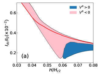

In order to obtain the overall ratchet effect in a narrow superconducting ring, we first systematically calculate the voltage signals for dc currents of opposite directions. Figure 2(a) presents the phase diagram of the ratchet signal as a function of the magnetic field and the amplitude of the dc current . The amplitudes of the voltage induced by a clockwise current is denoted as and that by a counter-clockwise current is denoted . The difference of the voltage values obtained for two opposite directions of the current is used to quantitatively describe the ratchet signal. Negative signals (pink) are found at low fields () independent of the current value. However, at high fields (), positive signals (blue) emerge at low currents, indicting a ratchet signal reversal. To the best of our knowledge, such a ratchet reversal has not been reported to date in a pinning-free superconducting system, neither experimentally nor in simulations.
To understand this phase diagram better, we show voltage-current (V-I) characteristics at three magnetic fields , , and in the panels (b-d) of Fig. 2, respectively. When the sample is driven to the normal state, the V-I characteristics follows ohmic behavior, which is indicated by dashed lines in the lower panels (b-d) of Fig. 2. Non-zero and zero voltage signals below the reference lines correspond to the dissipation state due to moving vortices (flux-flow state) and the zero-resistance superconducting state, respectively.
At the low field , as shown in Fig. 2 (b), in the dc currents range , the system has zero resistance for the clockwise current and turns to the normal state at counter-clockwise currents. In this case, pronounced negative ratchet signals are generated owing to the large voltage difference between the superconducting and the normal phase. In other words, the superconducting and normal conducting states can be fully switched by changing the direction of the applied current or magnetic field. Interestingly, this is exactly the superconducting diode effect, similar to that demonstrated in the artificial superlattice ando2020observation , providing a very economical way to fabricate a superconducting diode from the perspective of material design.
At the intermediate field , the ratchet signals are also all negative [see Fig. 2(c)]. Panels (b) and (c) of Fig. 2 indicate that the sample with counter-clockwise current (red) enters both the flux-flow state and the normal state earlier than in the case of clockwise current (blue), yielding a negative ratchet signal. On the other hand, at a higher magnetic field [see Fig. 2(c)], the sample in counter-clockwise current enters the flux-flow state later than in , which results in the positive ratchet signal at small current, while the transition to the normal state for still occurs earlier, so the negative ratchet signal is also present at high currents. At a high the sample can transit to the normal phase while it can still stay in the flux-flow state at the same value of . In this case, the ratchet signal should be extremely large because of the high normal state voltage, leading to pronounced negative signal at high currents in the phase diagram in Fig. 2(a). We note that the total magnetic field is the superposition of the external magnetic field and the field induced by the current. For a current-carrying ring, the total field is enhanced by the additional fields induced by (counter-clockwise) but suppressed by the fields of (clockwise). Therefore, the superconducting ring driven by reaches the normal phase earlier than when driven by .
From Fig. 2(d) one sees that the positive ratchet signal originates from the larger negative critical current at magnetic fields . In equilibrium simulations with zero applied current, we find that vortices can only penetrate the sample at fields , which inspired us to study the underlining mechanism in terms of vortex potential energy.
III.2 Mechanism based on potential energy of a single vortex
The energy barrier for the penetration of vortices is known to determine the critical current at which the superconductor enters the flux-flow state morgan2015measurement ; pekker2011weber ; maksimova1998mixed ; maksimova1998mixed ; likharev1971formation . At equilibrium state, a higher energy barrier near the edge indicates that a larger current is needed to drive vortices to the flux-flow state. In what follows, we discuss critical current behavior in terms of the single vortex potential in order to reveal the mechanism of the ratchet signal reversal.
The potential energy of a single vortex inside a symmetric superconducting strip has been well studied and thoroughly explored maksimova1998mixed ; likharev1971formation ; stan2004critical ; sanchez2007critical . In general, vortex potential energy consists of four parts: (i) vortex core energy, (ii) interaction energy between a vortex and its image, (iii) interaction energy with magnetic field, and (iv) interaction energy with the applied current. Following the ideas in these works, we perform conformal transformation to the potential energy of a strip, and obtain the vortex potential of a narrow superconducting ring as a function of the radial position of the ring:
| (4) |
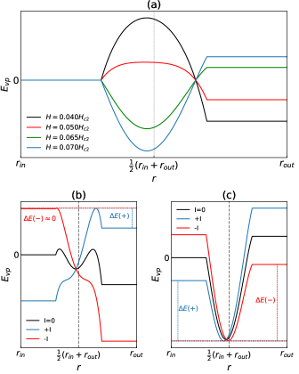
where is the superfluid stiffness, is the flux quantum, and is the bias current density. The scaling is changed due to the conformal transformation and the length is measured in units of : , , and . The logarithmic divergence near the edge is cut off by vortex core length scale maksimova1998mixed ; likharev1971formation , which leads to the flat platform near sample edges. As vortices are unstable in the vicinity of the boundary and would exit from the edge or enter the sample quickly, this approach remains valid for the purpose of our discussion. Without the loss of generality, we have absorbed the vortex core energy into the cut-off length scale. In Fig. 3(a), we plot the vortex potential at a few selected magnetic fields without external currents for a superconducting ring. Compared to that of straight nanowires morgan2015measurement ; pekker2011weber , the vortex potential of a ring-shaped superconductor inherits asymmetric energy barriers near its inner and outer edges. The vortex potential described here is qualitatively consistent with the analytical findings in the annular ring in a uniform applied field using the London approach kogan2004properties ; kirtley2003fluxoid . In low-current regime, the total potential is only tilted due to the Lorentz force and the asymmetric energy barriers at two edges are preserved, as shown in the lower panels of Fig. 3.
At low magnetic fields where , the energy barrier indicates that in equilibrium vortices cannot enter the sample, which is consistent with our numerical observations. Above the critical current, current-induced vortices driven by Lorentz force could enter at one edge and then exit from the other edge. In the present setup, vortices should move from the inner edge towards the outer edge at a counter-clockwise current (), and vice versa. In Fig. 3(b), the energy barrier for vortex entry with () is indicated by by the blue (red) lines. Since , the flux-flow state is easier to reach for , leading to a lower critical current for , and accordingly a negative ratchet signal.
However at higher fields (), the energy barriers are replaced by potential wells. Now vortices can appear inside the sample even in the absence of external current. In Fig. 3(c), we again use to denote the well depth associated to the current . In contrast to the low-field case, we now have . Therefore, vortices can exit from the inner edge easier than from the outer one, yielding a higher critical current for . In other words, at these fields, the ratchet signal turns to be positive. With further increase of the external current, approaching the current above which the sample transits to the normal state, the energy well difference at two edges becomes far less important due to the dominance of the Lorentz force. Therefore, in the high-current regime, the effect of the current-induced field discussed in Sec. III(A) dominates and the negative ratchet signal reappears.
IV Ratchet effects generated by ac currents
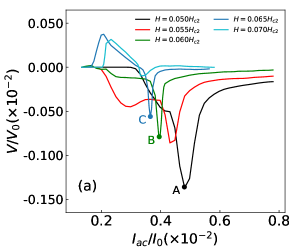
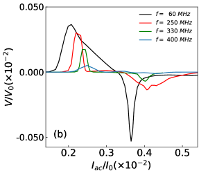
Next we study the response of the ring to the ac currents with zero mean. We apply a sinusoidal current to the sample, where . According to in typical MoGe samples wang2017parallel , the related frequency is about MHz. Our simulations suggest that such a frequency allows vortices to move across the strip within for a wide range of amplitudes . The mean dc voltage is obtained by averaging over five periods . As shown in Fig. 4(a), the rectified dc voltage is clearly observed in a finite range of magnetic fields. At low fields, only negative ratchet signals are observed. The ratchet signal decreases monotonously when the field is increased. With increasing magnetic field, we find that a positive ratchet signal arises at low currents while the negative signal remains in the high current range.
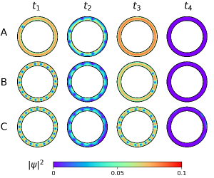
To understand the details of the negative ratchet process at high current, we plot in Fig. 5 snapshots of the Cooper-pair density at different times and within one period, at the three ratchet signal peaks A, B, and C marked in Fig. 4(a). After closer inspection, we find that the current at which the ratchet peak signal occurs is close to the dc current for the transition to the normal state. It implies that if the ac amplitude is comparable to the dc critical current to the normal state, the sample can transit to normal phase within one period. As shown in the rightmost panel of Fig. 5 at , the sample indeed enters the normal state with vanished order parameter . At the other three times, all earlier than , vortices are clearly present, corresponding to the flux-flow state. For detailed visualization of the vortex dynamics, the corresponding videos, Video-S1(A/B/C), are provided in supplemental material Supplemental . One can see from both the snapshots and the videos that during the first half-period, individual vortices can be clearly seen, suggesting that the sample remains in the flux-flow state. However, in the second half-period, the vortex cores overlap very quickly and the sample transits to the normal state before the end of the period. Due to the significant voltage difference between the two states, maximum ratchet effect occurs. Below the sample stays less time in normal state in the second half-period hence the ratchet signal decreases. Above , the normal state can be accessed in both half-periods, consequently the ratchet effect also becomes smaller. That is, the large difference of the voltages in the time intervals in which the sample stays in the normal phase and flux-flow state within one period results in the peak structure of the ratchet signal. In principle, current above which the sample is in the normal state decreases with the magnetic field, so the peak shifts to the low ac amplitude range. Accordingly, the corresponding negative signals should also become smaller, in agreement with our numerical observations in Fig. 4(a).
One may notice that in Fig. 5 vortex density is different at and when the external currents are both temporarily zero. Generally speaking, we have a larger vortex density at . Before , the sample just experiences the transition from the normal phase to the flux-flow state. Due to the non-adiabatic process, even at transient zero current, the vortex does not have sufficient time to be expelled from the sample, which leads to a higher vortex density.
The mechanism of the positive signals that emerge at lower ac amplitude is the same as that seen in the case of dc currents in Sec. III. As shown in Video-S2 in the supplemental material Supplemental , for at , in the first half-period (), the vortices can exit at the inner edge, while in the second half-period (), the vortices are locked inside the sample despite a finite Lorentz force. That is, in the first half-period, the sample enters the flux-flow state, while in the second half-period, the sample is still in the zero-resistance state, which yields the positive ratchet signals.
The effect of ac frequency on the ratchet signal is also studied. Without the loss of generality, the magnetic field was set to . Fig. 4(b) shows the mean voltage at various frequencies. The ratchet signals are more pronounced at low frequencies. With increasing frequency, both negative and positive signals decrease, and they gradually disappear at high frequencies. A video for vortex behavior at the same field and ac amplitude but at a higher ac frequency MHz is provided in Video-S3 in the supplemental material Supplemental . At a high frequency, the ac current period is so short that the vortices could not cross the ring during both the first and second half-period, and can only oscillate inside the superconductor. In this case, the vortex oscillation generates subtle difference in the voltages for two opposite current directions, hence the ratchet effect is strongly suppressed.
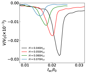
We have also simulated the response to the ac current in a wider ring-shaped superconductor. Figure 6 shows the ratchet voltage signal for a similar superconducting ring of size and . The frequency of the applied ac current was kept at MHz. With the increase of the ring width , the reversal of the ratchet signal would vanish, consistent with the experimental observation in the S20 sample of ji2017ratchet . The reason for the vanishing positive ratchet signal in a wider superconducting ring is that for large enough width, more than one vortex can be presented along the radial direction of the sample. Vortex-vortex interaction would not be negligible and the above picture for the single vortex potential in Sec. III B breaks down. Due to their repulsive interaction, vortices prefer to stay away from others, thus it is more difficult for the vortices to move to the inner edge (high vortex density) than towards the outer edge (dilute vortex density), which eventually results in the negative signal in all cases, excluding the possibility of the positive ratchet signal.
The ratchet effect in the pinning-free system with an asymmetric edge barrier here is stronger than those found in superconductors with asymmetric pinning potentials reichhardt2015reversible ; adami2015onset . In the latter case, the ratchet effects are generated by the difference in the velocities of vortices driven by opposite currents, in comparison with the former where the rectified signal is generated by the voltage difference between the flux-flow state and the zero-resistance state. As a consequence, the rectified voltage signal due to asymmetric pinning can be one or two orders of magnitude smaller than in case of asymmetric sample edge adami2015onset ; wu2015special ; ji2016vortex ; ji2017ratchet .
It has been reported in the literature that a rough edge can affects vortex dynamics alone cerbu2013vortex . In this paper, the sample boundary is assumed to be perfect, i.e. without local defects, so that we can focus exclusively on the effect of the asymmetric geometry on the ratchet signal. To confirm the present observation in experiments, we would suggest that both the clean superconducting ring with minimal edge roughness and the leads with very low dissipation should be fabricated to avoid unnecessary noise signals. On the other hand, a real sample always contains intrinsic, weak random pinning centers. However, the effects of this kind of pinning centers for the two opposite vortex motion currents are nearly the same, so the main picture proposed in this paper would not be affected.
Finally, as the signal reversal decreases with increasing sample width, it is also crucial that the ring width should be comparable to the vortex size in a finite range of temperature. With the ring width used in this paper, the reversible ratchet effect phenomenon can be convincingly observed in the temperature range of .
V Conclusion
In summary, we systematically studied the ratchet effect in a narrow superconducting ring using TDGL equations. The dc voltages in the presence of external dc currents at various magnetic fields were calculated first. We found a reversible ratchet effect using dc currents of opposite directions. The superconducting diode effect is also observed. Strong negative ratchet signals are found in the high current regime in a wide range of magnetic fields. Surprisingly, at high fields, a positive ratchet signal appears in the low current regime. It is shown in numerical simulations that different critical currents for two polarities of the current are the origin of the observed positive ratchet signal. It is further revealed that this unusual phenomenon can be attributed to the asymmetric vortex potential due to the ring-shaped structure.
Rectified voltage signals are also found when applying ac currents to the system. We observed pronounced negative voltage signals in a broad range of external fields while the positive ratchet signals were also observed in the weak ac amplitude regime. Further investigations suggest that positive ratchet signals observed with ac and dc current share the same origin. It is also demonstrated that with increasing ac frequency and ring width, the unusual positive ratchet signals weaken and eventually vanish.
The pronounced ratchet signals observed in the pinning-free but geometrically asymmetric system are generated from the switch of various phases, namely the zero-resistance phase, dissipative phase (flux-flow state), and the normal phase when the polarity of applied current is changed. Therefore, these signals are by default larger than those caused by the different vortex velocities within the same phase in systems with asymmetric pinning potentials. As a result, the large and reversible ratchet signal seen in our simulations should stimulate further experimental investigations and its use in superconducting circuits or devices, including superconducting diodes and single-photon detectors.
ACKNOWLEDGEMENTS We are grateful to G. Berdiyorov for useful suggestions and comments. Q.H.C. thanks Beiyi Zhu for helpful discussions during the early stage of this work. This work is supported in part by the National Key Research and Development Program of China (No.2017YFA0303002) (Q.H.C. and J.J.) and (2018YFA0209002) (Y.L.W.); and the National Natural Science Foundation of China (Nos. 11834005, 11674285, 61771235, and 61727805). Z.L.X. acknowledges support by the U. S. Department of Energy, Office of Science, Basic Energy Sciences, Materials Sciences and Engineering and the National Science Foundation under Grant No. DMR-1901843. F. M. Peeters and M. V. Milos̆ević acknowledge support by the Research Foundation - Flanders (FWO).
References
- (1) C.-S. Lee, B. Jankó, I. Derényi, and A.-L. Barabási, Nature 400, 337 (1999).
- (2) J. F. Wambaugh, C. Reichhardt, C. J. Olson, F. Marchesoni, and F. Nori, Phys. Rev. Lett. 83, 5106 (1999).
- (3) C. J. Olson, C. Reichhardt, B. Jankó, and F. Nori, Phys. Rev. Lett. 87, 177002 (2001).
- (4) J. E. Villegas et al., Science 302, 1188 (2003).
- (5) V. K. Vlasko-Vlasov et al., Phys. Rev. B 95, 144504 (2017).
- (6) B. Y. Zhu, F. Marchesoni, and F. Nori, Phys. Rev. Lett. 92, 180602 (2004).
- (7) I. S. Veshchunov et al., Nat. Commun. 7, 12801 (2016).
- (8) F. Qin et al., Nat. Commun. 8, 14465 (2017).
- (9) K. Yasuda et al., Nat. Commun. 10, 2734 (2019).
- (10) R. Wakatsuki et al., Sci. Adv. 3, e1602390 (2017).
- (11) F. Ando et al., Nature 584, 373 (2020).
- (12) V. Rouco et al., New J. Phys. 17, 073022 (2015).
- (13) B. Y. Zhu, F. Marchesoni, V. V. Moshchalkov, and F. Nori, Phys. Rev. B 68, 014514 (2003).
- (14) O.-A. Adami et al., Phys. Rev. B 92, 134506 (2015).
- (15) C. Reichhardt, D. Ray, and C. J. O. Reichhardt, Phys. Rev. B 91, 184502 (2015).
- (16) C. Reichhardt and C. J. O. Reichhardt, Phys. Rev. B 93, 064508 (2016).
- (17) C. O. Reichhardt et al., Physica C 533, 148 (2017).
- (18) J. Ji et al., Appl. Phys. Lett. 109, 242601 (2016).
- (19) J. Ji et al., Supercond. Sci. Technol. 30, 105003 (2017).
- (20) G. R. Berdiyorov, M. V. Milošević, and F. M. Peeters, Appl. Phys. Lett. 100, 262603 (2012).
- (21) H. L. Hortensius, E. F. C. Driessen, T. M. Klapwijk, K. K. Berggren, and J. R. Clem, Appl. Phys. Lett. 100, 182602 (2012).
- (22) N. Schildermans et al., Phys. Rev. B 76, 224501 (2007).
- (23) O.-A. Adami et al., Appl. Phys. Lett. 102, 052603 (2013).
- (24) D. Y. Vodolazov and F. M. Peeters, Phys. Rev. B 72, 172508 (2005).
- (25) G. R. Berdiyorov, M. V. Milošević, and F. M. Peeters, Phys. Rev. B 81, 144511 (2010).
- (26) D. Halbertal et al., Nature 539, 407 (2016).
- (27) P. K. Day, H. G. LeDuc, B. A. Mazin, A. Vayonakis, and J. Zmuidzinas, Nature 425, 817 (2003).
- (28) M. Mittendorff et al., Appl. Phys. Lett. 103, 021113 (2013).
- (29) G. R. Berdiyorov et al., Phys. Rev. B 86, 224504 (2012).
- (30) G. R. Berdiyorov et al., Phys. Rev. Lett. 109, 057004 (2012).
- (31) J. M. Blatt and C. J. Thompson, Phys. Rev. Lett. 10, 332 (1963).
- (32) N. Giordano, Phys. Rev. Lett. 61, 2137 (1988).
- (33) J. S. Langer and V. Ambegaokar, Phys. Rev. 164, 498 (1967).
- (34) D. E. McCumber and B. I. Halperin, Phys. Rev. B 1, 1054 (1970).
- (35) A. Johansson, G. Sambandamurthy, D. Shahar, N. Jacobson, and R. Tenne, Phys. Rev. Lett. 95, 116805 (2005).
- (36) A. Kenawy, W. Magnus, M. V. Milošević, and B. Sorée, Supercond. Sci. Technol. 33, 125002 (2020).
- (37) T.-C. Wu, L. Horng, and J.-C. Wu, J. Appl. Phys. 117, 17A728 (2015).
- (38) See Supplemental Material at [DOI: 10.1103/PhysRevB.103.014502] for visualization of vortex dynamics at various magnetic fields.
- (39) K.-H. Bennemann and J. B. Ketterson, Superconductivity: Volume 1: Conventional and Unconventional Superconductors, Volume 2: Novel Superconductors (Springer, 2008).
- (40) R. Kato, Y. Enomoto, and S. Maekawa, Phys. Rev. B 47, 8016 (1993).
- (41) T. Winiecki and C. S. Adams, J. of Comput. Phys. 179, 127 (2002).
- (42) R. Córdoba et al., Sci. Rep. 9, 12386 (2019).
- (43) Y.-L. Wang et al., PNAS 114, E10274 (2017).
- (44) D. Y. Vodolazov, F. M. Peeters, M. Morelle, and V. V. Moshchalkov, Phys. Rev. B 71, 184502 (2005).
- (45) T. Morgan-Wall, B. Leith, N. Hartman, A. Rahman, and N. Marković, Phys. Rev. Lett. 114, 077002 (2015).
- (46) D. Pekker, G. Refael, and P. M. Goldbart, Phys. Rev. Lett. 107, 017002 (2011).
- (47) G. M. Maksimova, Phys. Solid State 40, 1607 (1998).
- (48) K. K. Likharev, Sov. Radiophys. 14, 722 (1972).
- (49) G. Stan, S. B. Field, and J. M. Martinis, Phys. Rev. Lett. 92, 097003 (2004).
- (50) P. Sánchez-Lotero and J. J. Palacios, Phys. Rev. B 75, 214505 (2007).
- (51) V. G. Kogan, J. R. Clem, and R. G. Mints, Phys. Rev. B 69, 064516 (2004).
- (52) J. R. Kirtley et al., Phys. Rev. B 68, 214505 (2003).
- (53) D. Cerbu et al., New J. Phys. 15, 063022 (2013).