PHOENIX: Device-Centric Cellular Network Protocol Monitoring using Runtime Verification111 This is the extended version of the NDSS 2021 paper with the same title.
Abstract
End-user-devices in the current cellular ecosystem are prone to many different vulnerabilities across different generations and protocol layers. Fixing these vulnerabilities retrospectively can be expensive, challenging, or just infeasible. A pragmatic approach for dealing with such a diverse set of vulnerabilities would be to identify attack attempts at runtime on the device side, and thwart them with mitigating and corrective actions. Towards this goal, in the paper we propose a general and extendable approach called Phoenix for identifying n-day cellular network control-plane vulnerabilities as well as dangerous practices of network operators from the device vantage point. Phoenix monitors the device-side cellular network traffic for performing signature-based unexpected behavior detection through lightweight runtime verification techniques. Signatures in Phoenix can be manually-crafted by a cellular network security expert or can be automatically synthesized using an optional component of Phoenix, which reduces the signature synthesis problem to the language learning from the informant problem. Based on the corrective actions that are available to Phoenix when an undesired behavior is detected, different instantiations of Phoenix are possible: a full-fledged defense when deployed inside a baseband processor; a user warning system when deployed as a mobile application; a probe for identifying attacks in the wild. One such instantiation of Phoenix was able to identify all 15 representative n-day vulnerabilities and unsafe practices of 4G LTE networks considered in our evaluation with a high packet processing speed (68000 packets/second) while inducing only a moderate amount of energy overhead (4mW).
1 Introduction
Along with global-scale communication, cellular networks facilitate a wide range of critical applications and services including earthquake and tsunami warning system (ETWS), telemedicine, and smart-grid electricity distribution. Unfortunately, cellular networks, including the most recent generation, have been often plagued with debilitating attacks due to design weaknesses [31, 32, 33, 14] and deployment slip-ups [56, 38, 28, 45]. Implications of these attacks range from intercepting and eavesdropping messages, tracking users’ locations, and disrupting cellular services, which in turn may severely affect the security and privacy of both individual users and primary operations of a nation’s critical infrastructures. To make matters worse, vulnerabilities discovered in this ecosystem take a long time to generate and distribute patches as they not only require collaboration between different stakeholders (e.g., standards body, network operator, baseband processor manufacturer) but also incur high operational costs. To make matters worse, different patches could potentially lead to unforeseen errors if their integration is not accounted for.
In addition to it, although a majority of the existing work focus on discovering new attacks through analysis of the control-plane protocol specification or deployment [31, 32, 56, 38, 14, 33, 28, 45], only a handful of efforts have focused on proposing defense mechanisms or any apparatus to detect attack occurrences [23, 42, 47, 59, 34]. Unfortunately, these proposed mechanisms are far from being widely adopted since they suffer from one of the following limitations: (i) Requires modifications to an already deployed cellular network protocol [34] which require network operator cooperation; (ii) Focuses on identifying particular attacks and hence are not easily extensible [23, 42, 47, 59]; and (iii) Fails to handle realistic scenarios (e.g., roaming) [34].
A pragmatic approach for protecting users and their devices from such a wide-variety of vulnerabilities and dubious practices of the operators (referred to as undesired behavior222 In our context, not all undesired behavior are necessarily exploitable attacks. We also call some not-necessarily-malicious behavior (e.g., the use of null encryption by real network operators) undesired behavior if they can be detrimental to a user’s privacy and security. In our exposition, we use attack, vulnerability, and undesired behavior, interchangeably. at the abstract in this paper) is to deploy a device-centric defense. Such a defense, similar to an intrusion prevention system in principle, will monitor the network traffic at runtime to identify undesired behavior and then take different corrective actions to possibly thwart it (e.g., dropping a packet). In this paper, we focus on the core problem of developing a general, lightweight, and extendable mechanism Phoenix that can empower cellular devices to detect various undesired behavior. To limit the scope of the paper, we focus on monitoring the control-plane traffic for undesired behavior, although Phoenix is generalizable to data-plane traffic. Monitoring control-plane traffic is vital as flaws in control-plane procedures, such as registration and mutual authentication, are entry points for most attacks in both control- and data-plane procedures.
Phoenix’s undesired behavior detection approach can induce different instantiations depending on the corrective actions that are available to it. When deployed inside a baseband processor, Phoenix can be used as a full-fledged device-centric defense, akin to the pragmatic approach discussed above, that intercepts each message before getting processed by the message handler and take corrective actions (e.g., drop the message, terminate the session) when it identifies the message as part of an attack sequence. Alternatively, if Phoenix is deployed as a mobile application that can obtain a copy of the protocol message from the baseband processor, then one can envision building a warning system, which notifies device owners when it detects that a protocol packet is part of an undesired behavior. Finally, Phoenix can be deployed and distributed as part of cellular network probes or honeypots that log protocol sessions with undesired behavior.
Approach.
In this paper, we follow a behavioral signature-based attack (or, generally undesired behavior) detection approach. It is enabled by the observation that a substantial number of cellular network undesired behavior, which is detectable from the device’s point-of-view, often can be viewed as protocol state-machine bugs. Signatures of such undesired behavior can be constructed by considering the relative temporal ordering of events (e.g., receiving an unprotected message after mutual authentication).
Based on this above insight, we design a lightweight, generic, and in-device runtime undesired behavior detection system dubbed Phoenix for cellular devices. In its core, Phoenix’s detection has two main components: (1) a pre-populated signature database for undesired behavior; (2) a monitoring component that efficiently monitors the device’s cellular network traffic for those behavioral signatures and takes corresponding corrective measures based on its deployment (e.g., drop a message, log a message, warn the user). Such a detection system is highly efficient and deployable as it neither induces any extra communication overhead nor calls for any changes in the cellular protocol. Phoenix works with only a local view of the network, yet is effective without provider-side support in identifying a wide array of undesired behavioral signatures.
For capturing behavioral signatures, we consider the following three different signature representations that induce different tradeoffs in terms of space and runtime overhead, explainability, and detection accuracy: (1) Deterministic Finite Automata (DFA); (2) Mealy machine (MM) [44]; (3) propositional, past linear temporal (PLTL) [51] formulas. Cellular network security experts can add behavioral signatures in these representations to Phoenix’s database. In case an expert is not familiar with one of the above signature representations, they can get help/confirmation from an optional automatic signature synthesis component we propose. We show that for all the above representations the automatic signature synthesis problem can be viewed as an instance of the language learning from the informant problem. For DFA and MM representations, we rely on existing automata learning algorithms, whereas for PLTL, we propose a new algorithm, an extension of prior work [46]. For runtime monitoring of these signature representations in Phoenix, we use standard algorithms [29].
We consider two different instantiations for Phoenix. First, we implemented Phoenix as an Android application and instantiated with the following monitors: DFA-based, MM-based, and PLTL-based. In Phoenix app, for capturing in-device cellular traffic, we enhanced the MobileInsight Android [41] application to efficiently parse messages and invoke the relevant monitors. Second, we implemented Phoenix inside srsUE, distributed as part of the open-source protocol stack srsLTE [27], powered by the PLTL-based monitor—the most efficient in our evaluation, to mimic Phoenix’s deployment inside the baseband processor.
We evaluated Phoenix’s Android app instantiation based on both testbed generated and real-world network traffic in 3 COTS devices. In our evaluation with 15 existing cellular network attacks for 4G LTE, we observed that in general all of the approaches were able to identify the existing attacks with a high degree of success. Among the different monitors, however, DFA on average produced a higher number of false positives (21.5%) and false negatives (17.1%) whereas MM and PLTL turn out to be more reliable; producing a significantly less number of false positives ( 0.03%) and false negatives ( 0.01%). In addition, we observed that all monitors can handle a high number of control-plane packets (i.e., 3.5K-369K packets/second). We measured the power consumption induced by different monitors and observed that on average, they all consume a moderate amount of energy ( 2-6 mW). Interestingly, we discover that Phoenix, when powered by the PLTL-based monitor, produces no false warnings on real networks and in fact, it helped us discover unsafe network operator practices in three major U.S. cellular network providers. Finally, we evaluated Phoenix instantiation as part of srsUE [27] with testbed generated traffic and observed that it only incurs a small memory overhead (i.e., 159.25 KB).
Contributions.
In summary, the paper makes the following contributions:
-
•
We design an in-device, behavioral-signature based cellular network control-plane undesired behavior detection system called Phoenix. We explore the design space of developing such a vulnerability detection system and consider different trade-offs.
-
•
We implement Phoenix as an Android app, which during our evaluation with 3 COTS cellular devices in our testbed has been found to be effective in identifying 15 existing 4G LTE attacks while incurring a small overhead.
-
•
We implement Phoenix by extending srsUE [27]—mimicking a full-fledged defense, and show its effectiveness at preventing attacks.
-
•
We finally show how one could automatically synthesize behavioral signatures Phoenix expects by posing it as a learning from an informant problem [24] and solve it with different techniques from automata learning and syntax-guided synthesis.
2 Preliminaries
In this section, we briefly overview the background material necessary to understand our technical discussions.
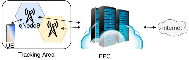
LTE Architecture. The LTE network ecosystem can be broken down into 3 main components (See Figure 1): User Equipment (UE), Evolved Packet Core (EPC) and the Radio Access Network (E-UTRAN). The UE is a cellular device equipped with a SIM card. Each SIM card contains a unique and permanent identifier known as the International Mobile Subscriber Identity (IMSI). Also, each device comes with a unique and device-specific identifier called International Mobile Equipment Entity (IMEI). As both the IMSI and IMEI are unique and permanent, their exposure can be detrimental to a user’s privacy and security. In LTE, the coverage area of a network can be broken down into hexagon cells where each cell is powered by a base station (eNodeB). The network created by the base stations powering up the coverage area and the UE is referred to as E-UTRAN. The Evolved Packet Core (EPC) is the core network providing service to users. The EPC can be seen as an amalgamation of services running together and continuously communicating with one another.
LTE Protocols. The LTE network protocol consists of multiple layers, however, this paper focuses only on the Network Layer. This layer consists of 3 protocols: NAS (Non-access Stratum), RRC (Radio Resource Control), and IP (Internal Protocol). In this paper, we only explore NAS and RRC. The NAS protocol is the logical channel between the UE and the EPC. This protocol is in charge of highly critical procedures such as the attach procedure which provides mutual authentication between the EPC and the UE. The RRC protocol can be seen as the backbone of multiple protocols, including NAS. In addition, RRC is the main channel between the UE and the eNodeB.
Past-Time Propositional Linear Temporal Logic (PLTL). PLTL extends propositional logic with past temporal operators and allows a succinct representation of the temporal ordering of events. Therefore, we use it as one of our vulnerability signature representation. Here, we only provide a brief overview of PLTL but the detailed presentation can be found elsewhere [43]. The syntax of PLTL is defined inductively below where (possibly, with subscripts) are meta-variables denoting well-formed PLTL formulas.
In the above presentation, and refer to Boolean constants true and false, respectively. The propositional variable is drawn from the set of a fixed alphabet (i.e., a set of propositions). PLTL supports unary operators , as well as binary operators . The Boolean logical operators include (not), (disjunction), and (conjunction) and the temporal operators include (yesterday), (once), (historically), and (since). We will now discuss the semantics of PLTL.
The Boolean logic operators in PLTL have their usual definition as in propositional logic. We fix an alphabet (i.e., a set of propositions) for the PLTL formulas and consider it in the rest of the paper. The semantics of PLTL is given with respect to a Kripke structure. In a Kripke structure [40], a trace is a finite sequence of states that maps propositions in to Boolean values at each step 333We write to denote . (i.e., ). Although, the standard PLTL semantics are defined over (infinite) traces, we are only required to reason about finite traces.
Definition 1 (Semantics)
Given a PLTL formula and a finite trace of length , the satisfiability relation ( holds at position ) is inductively defined as follows:
-
•
iff
-
•
iff
-
•
iff
-
•
iff
-
•
iff and
-
•
iff or
-
•
iff and
-
•
iff
-
•
iff .
-
•
iff and
Intuitively, (read, Yesterday ) holds in the current state if and only if the current state is not the initial state and held in the previous state. holds true currently if and only if held in any previous state (inclusive) and held in all successive states including the current one. The rest of temporal operators (read, true once in the past) and (read, always true in the past) can be defined through the following equivalences: .
3 Overview of PHOENIX
In this section, we discuss the scope, threat model, challenges, and requirements of a Phoenix like system. We conclude by presenting two concrete instantiations of Phoenix, namely, as a warning system and a full-fledged defense.
3.1 Undesired Behavior and Scope
In our presentation, we define an undesired behavior/vulnerability broadly to include inherent protocol flaws at the design-level, an exploitable implementation vulnerability of the baseband processor, an exploitable misconfiguration or deployment choice of a network operator, and unsafe security practices by a baseband manufacturer and network operator. For instance, not using encryption for protecting traffic is considered a vulnerability in our presentation. Even though null encryption is permitted by the specification on the NAS layer [1], we argue that this is an unsafe practice since subsequent NAS traffic (e.g., SMS over NAS [38, 31]) would be exposed in plaintext.
In this paper, we focus on the undesired behavior of the 4G LTE control-plane protocols, i.e., protocols running in the NAS and RRC layers [31, 32, 56, 38, 14, 33, 28, 45]. Among these attacks, we focus on attacks that are detectable from the device’s perspective and can be viewed as undesired outcomes of protocols’ state-machines. One distinct advantage of a device-centric attack detection mechanism is that certain attacks necessarily cannot be observed by the network operators, which is observable only from the device vantage point. Examples of such attacks include ones that require an adversary setting up a fake base station that lures the victim device and then launch an attack [31, 38, 32]. Attacks that target other network components or employ adversary’s passive sniffing capabilities are out of scope as they are not detectable through in-device traffic monitoring [32, 54, 37]. In addition, the current instantiations of Phoenix do not support attacks that require reasoning about quantitative aspects (e.g., the number of certain messages received in a time window) of the protocol (e.g., ToRPEDO attack [32]). Please consult Table 8 in the Appendix for an exhaustive list of Phoenix supported and unsupported attacks.
3.2 Threat Model
We consider an adversary with the following capabilities: (1) He has access to malicious cellular devices with legitimate credentials; (2) He can setup a rouge base station, cloning parameters of a legitimate one, provides a higher signal strength than legitimate base stations within the vicinity. (3) He can setup a base station which acts as a relay between the device and legitimate base station, enabling him to drop, replay, and inject messages at will while respecting cryptographic assumptions; (4) For targeted attacks, we assume the attacker has access to the victim’s soft identity such as phone number and social network profile. We assume that the device in which Phoenix runs is not compromised.
3.3 Example: A Privacy Attack on Radio Link Failure (RLF) Report
In cellular networks, there is essentially no authentication mechanism between a device and the base station during the connection initiation with the core network. The device trusts the base station emitting the highest signal strength and establishes an unsafe connection with it using unprotected RRC layer messages. The base station acts as the trusted intermediary to facilitate communication between the device and core network. Once the device and core network mutually authenticate each other, they setup a security context making all the following control-plane messages to be encrypted and integrity protected. One such control-plane message is the which contains neighboring base stations’ signal strengths (and, optionally the device’s GPS coordinates). This is used to identify potential failures and aids when identifying coverage problems.
A privacy attack against this RLF report message [56] proceeds by luring a cellular device to connect to a rogue base station, which exploits the lack of authentication of initial broadcast messages as well as the unprotected RRC connection setup in the bootstrapping phase. Before setting up the security context (with protected and messages) at the RRC layer, the rogue base station sends an unprotected message to the device. This triggers the device to respond with a message (if it posses one) in the clear. Since the RLF report includes signal strength measurements of neighboring cells (and optionally GPS coordinates), the attacker can use that information to triangulate the victim’s location.
3.4 Challenges
Realizing the vision of Phoenix has the following challenges. (C-1) An attack detection mechanism like Phoenix has to be lightweight, otherwise substantial overhead can impede adoption due to negatively impacting the user’s Quality-of-service (QoS). (C-2) The system must be able to operate in a standalone fashion without requiring assistance from network operators. (C-3) The system must be attack- and protocol-agnostic, and amenable to extension to new attacks discovered after its deployment and future protocol versions (e.g., 5G). (C-4) The detection accuracy of the system must be high (i.e., low false positives and negatives). If the system incurs a large number of false positives, then in its instantiation as part of the baseband processor, can create interoperability issue. In the same vein, false positives in Phoenix’s instantiation as a warning system can overwhelm the user, making her ignore the raised warnings. A large number of false negatives, on the other hand, makes the system prone to vulnerabilities. (C-5) The attack detection system should detect the attack as soon as it is feasible when the malicious session is underway. As an example, let us consider the above attack on RLF report. If a detection system identifies the attack only after the device has already sent the message in the clear to the adversary then the attack has happened and this reduces the impact of a detection system like Phoenix. An effective detection mechanism will identify the attack as soon as the device receives the unprotected before security context establishment in which case it can thwart the attack.
3.5 PHOENIX Architecture
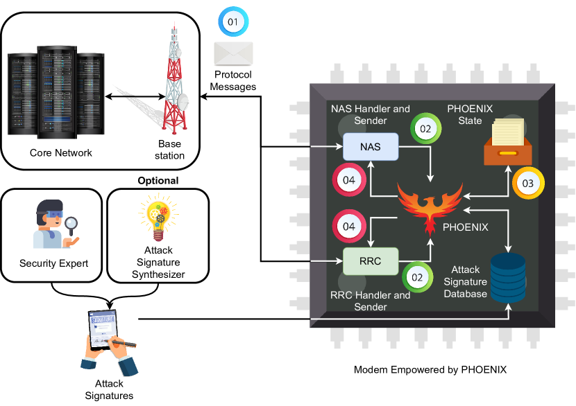
We now discuss the architecture of Phoenix in two settings: (1) when it is deployed inside a baseband processor as a full-fledged defense (see Figure 2); (2) when it is deployed as an Android application and serves as a warning system (see Figure 3).

PHOENIX Components.
In its purest form (Figure 2), Phoenix has two main components, namely, Attack Signature Database and Monitor.
Attack Signature Database. Phoenix expects a pre-populated attack signature database containing the signatures of attacks it is tasked to detect. An example attack signature for the privacy attack on RLF report above is: receiving the unprotected message before security context establishment in a session. Note that, a signature that requires the device to send a message before security context establishment is ineffective as it detects the attack only after it has occurred. Signatures can be generated by cellular network security experts, possibly in collaboration with an optional Phoenix component that can automatically generate candidate signatures from benign and attack traces.
Monitor. The monitor component analyzes the decoded messages and payloads (potentially, received from the message extractor component discussed below in case of Android app deployment), and matches them with its pre-populated undesired behavioral signature database. In case a behavioral signature is identified, the action of monitor component depends on the deployment scenario. For its baseband processor deployment, the monitor communicates the violation information to a corrective action module who can either terminate the session or drop the particular message depending on the signature. In its Android app deployment, it identifies which vulnerabilities have occurred and returns this information to the user along with possible remedies, if any exists.
For its instantiation as an Android app, Phoenix requires an additional component called message extractor. It gathers information about incoming/outgoing traffic (e.g., decoding a protocol message) between the baseband processor and network. This collected information (e.g., message type, payload) is then fed into the monitor component for vulnerability detection. Note that, in the baseband deployment, Phoenix does not require this component as the baseband processor inherently decodes and interprets the messages.
Workflow of PHOENIX.
The workflow of Phoenix deployed as an Android app is given below. The baseband deployment does not require step (1) of the workflow.
(1) The message extractor intercepts an incoming/outgoing protocol message and decodes it. (2) Pre-defined predicates over this message (and, its payload) are then calculated and sent to the monitor. (3) The monitor then classifies the ongoing trace as either benign or vulnerable (with label). (4) If Phoenix identifies a vulnerability, it either drops the message/terminates the connection when implemented inside a baseband processor, or alerts the user of the undesired behavior with possible remedies when deployed as an Android app (see Figure 11 for an example)
4 Vulnerability Signatures and Monitors
In this section, we discuss the possible vulnerability signature representations and their monitors that we consider.
4.1 Insight on Vulnerability Signatures
After analyzing existing control-plane attacks on 4G LTE [31, 32, 56, 38, 14, 33, 28, 45], we observed that a substantial amount of these attacks have very specific behavioral signatures when considering protocol messages, their payloads, and predicates over them. Precisely, considering the relative ordering of events often are sufficient to synthesize a discernible and precise vulnerability signature. For instance, in the running example described in Section 3.3, not seeing both the and messages prior to the being exposed, can serve as a confident indicator for such vulnerability.
4.2 Vulnerability Signature Representations
To precisely capture the behavioral signatures of cellular network vulnerabilities, we consider regular languages and PLTL as two possible representations. These formalisms are chosen due to their effectiveness in capturing relative temporal ordering of events as well as being efficiently monitorable at real-time. In addition, there is one more representational question we have to address: Does one keep per-vulnerability‘ signatures or one giant signature capturing all of the considered vulnerabilities? These design choices induce the following signature representations.
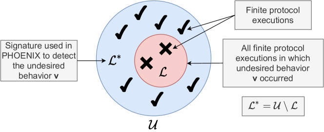
Signatures as Regular Languages. In this scheme, let us consider to be all finite protocol execution traces. Let us denote all the finite protocol executions in which a given vulnerability occurs as a regular language . Then the behavioral vulnerability signature we consider is the language which is the complement of and accepts all finite protocol execution traces where does not happen (See Figure 4). This signifies that will only reject traces in which happens. For representing , we consider the protocol message types, their payloads, and predicates over them as the alphabet. For a given vulnerability whose behavioral signature is denoted by , we represent its signature as a deterministic finite automata (DFA). For the case of having one giant signature for all vulnerabilities, we use a Mealy Machine whose outputs in the transitions indicates whether a certain execution is benign (labeled with output benign) or vulnerable in which case the output label identifies the vulnerability.
Signatures as PLTL formulas. PLTL has been shown to be a natural candidate for succinctly representing the temporal ordering of events of the past. We use message types, their payloads, and predicates over them as propositions of the logic. In this scheme, we keep one behavioral signature as a PLTL formula for each vulnerability that rejects only those finite traces in which the vulnerability in question occurs. We do not keep a giant PLTL formula for all vulnerabilities as it would not allow us to identify the particular vulnerability that occurs, impairing us to provide vulnerability-specific remedies and severity.
4.3 Vulnerability Monitors
We now discuss how we monitor vulnerability signatures based on their representations.
Monitoring Regular Language Signatures.
For monitoring a signature represented as a DFA, we need to store the DFA along with the current state in the memory. When a new packet and its associated information arrives to the monitor, we try to take a transition in DFA. If the transition lands us on a non-accepting state that means a vulnerability has been observed in which case we raise an alarm and provide vulnerability-specific information (e.g., name of the vulnerability, severity, and remedies). In case of a benign scenario, we just take the transition and update the current state. The monitoring with respect to a Mealy Machine is very similar with the one difference is that the output label of the transition indicates whether a vulnerability has been observed, and if so which particular vulnerability was observed.
Monitoring PLTL Signatures.
For monitoring PLTL formulas, we consider a standard dynamic programming (DP) based approach from the literature of runtime verification [26, 15, 16, 19, 20, 53].
In this approach, to monitor a PLTL formula , the monitor requires one bit of information for each sub-formula of . This bit signifies whether the associated formula holds true in the current state. If the truth value bit of is true in the current state, then there is no vulnerability. For a given PLTL formula , let us assume that represents the truth value bit of formula at position of the trace. Adhering to the PLTL semantics, the DP algorithm constructs from and the current state in the following way. Note that, we just need to store to calculate . The current state in our presentation is a total map which maps each propositional variable in the alphabet to either true or false.
5 Automated Vulnerability signature Synthesis
We now discuss the design of the optional Phoenix component called signature synthesizer.
5.1 Potential Application of the Signature Synthesizer
For using the Phoenix system, we want to emphasize it is not mandatory to have the signature synthesizer component; a cellular network security expert will suffice for generating signatures. Despite that, an automatic signature synthesizer can be useful to the expert in the following three scenarios.
First, when a cellular network security expert knows the root cause of an attack but does not know how to represent it one of the forms, then it can use the signature synthesizer to generate a candidate signature. DFA and MM signatures can be particularly complex. Please see Figure 12 in the Appendix for the DFA signature of the AKA bypass attack [38]. Second, when an expert neither knows the root cause of a newly discovered attack nor knows the signature representation, the signature synthesizer, especially the PLTL synthesizer because of its ability to generate succinct signatures, can be particularly helpful for not only identifying the root cause but also to synthesize the signature in the appropriate representation. Finally, the runtime and space overheads of monitors, especially the PLTL-based monitor, are proportional to the length of the signature. As the PLTL signature synthesizer is guaranteed to generate the minimum length signature, it induces an efficient monitor. We envision a more collaborative process between the automatic signature synthesizer and a human expert; instead of completely bypassing the expert and only using the synthesizer in a standalone fashion. In this envisioned process, the human expert asks the synthesizer to generate multiple candidate signatures and then chooses the one she finds more appropriate. Such a collaborative interaction reliefs the human expert to be also an expert of formal logic like PLTL.
5.2 The Problem of Signature Synthesis
The signature synthesis problem is an instance of the language learning from the informant problem [24]. In this problem, for a fixed alphabet , an informed learning sample (i.e., training dataset) is given which comprises of two disjoint sets of strings and , such that . The aim is to learn an observationally consistent language that accepts all strings in and rejects all strings in . In our setting, without the loss of generality, for a given vulnerability v the set are vulnerable execution traces in which v happens and the set are (benign) traces in which v does not happen. Then the learned observationally consistent language represents the vulnerability signature for v.
5.3 Regular Language Signature Synthesis
The observationally consistent language is considered to be regular and we used variations of the RPNI (Regular Positive and Negative Inference) algorithm [48] to learn both DFA and Mealy machine based vulnerability signatures. The complexity time of RPNI is the following: , where is the total number of states in the negative traces, is the total size of the alphabet, and is the number of unique prefixes [48]. Below we discuss how to prepare and that are required inputs to the RPNI algorithm.
DFA Signature Synthesis.
For a given vulnerability , we are given two sets of traces (i.e., does not happen in these traces) and (i.e., happens in these traces) such that . For each positive trace , we add and all its prefixes to . We set . We then invoke the RPNI [48] algorithm for obtaining a DFA signature for .
Mealy Machine Signature Synthesis.
We are given a set of vulnerabilities For each such vulnerability , we are given two sets of traces (i.e., does not happen in these traces) and (i.e., happens in these traces) such that . For each positive trace , we add to and assign the output label benign. We add each negative trace to with output label and then invoke the RPNI algorithm for obtaining a combined Mealy machine signature for all vulnerabilities in
5.4 PLTL Signature Synthesis
A PLTL formula represents the observationally consistent language that constitutes a vulnerability signature. For synthesizing PLTL signatures, we propose a syntax-guided synthesis algorithm that extends Neider and Gavran [46] to learn PLTL formulas using only finite length traces. The proposed algorithm reduces the signature synthesis problem to a Boolean satisfaction problem (SAT) and then solve it using an off-the-shelf SAT solver. In this setting, any satisfiable assignment (or, a model) of that SAT problem instance is used to derive observationally consistent PLTL signature. We aim to learn minimal consistent signatures as they can capture a concise vulnerability behavior even from a smaller training dataset and are also intellectually manageable (readable). This feature is inherent to this algorithm in contrast to other representations (i.e., DFA and Mealy machine). Precisely, a formula is minimally consistent with if and only if is consistent with and for every other PLTL formula such that , is inconsistent. Here is a function that takes a PLTL formula as input and returns the number of its sub-formulas. Also, this algorithm can provide different candidate signatures for a given sample by enumerating different models of the SAT problem. Thus, it provides the user with more flexibility to select the most desirable signature among the suggested candidates.
Input: Training dataset
and alphabet
Output: Minimally consistent signature of size
Algorithm.
For a given training dataset and alphabet (i.e., a set of propositional variables), our learning algorithm (Algorithm 1) iterates over the depth of the PLTL formula abstract syntax tree (AST) in ascending order. For a given depth of the formula AST , the algorithm has two main steps: ❶ Generate all possible PLTL formulas whose AST depth is exactly ; ❷ Check whether one of the generated formulas is consistent with . Although logically the algorithm has two steps, one can use a SAT solver to perform both searches simultaneously. The advantage of such an approach is that the constraints capturing the restrictions in step ❷ can rule out formulas from search at step ❶. We now, at a high-level, describe how both steps are encoded as a SAT formula.
The first set of constraints are regarding the syntax of the PLTL formula. These constraints are conjunctions of the following: (1) constraints for generating all ASTs of depth ; (2) constraints for assigning labels (i.e., propositions and operators) to the AST nodes. Example constraints in the label assignment include operators cannot be assigned to leaf nodes, and binary operators can only be assigned to nodes having two children. These constraints are required to be strong enough to ensure that only syntactically well-formed PLTL formulas are considered [21]. Based on PLTL semantics, the second set of constraints capture that the synthesized formula should satisfy all traces in while rejecting all traces in .
The encode function in the algorithm, given the AST depth and the training dataset , generates a propositional formula that capture these constraints. The algorithm then uses an off-the-shelf SAT solver to search for a model of . If a model is found, it is decoded to obtain an PLTL formula that represents the consistent vulnerability signature. If no model is found, the algorithm increments the bound size (i.e., ) and the search procedure continues until a satisfying assignment is found or the bound threshold is exceeded (i.e., ).
6 Implementation of Phoenix
We instantiate Phoenix in two settings: a full-fledged defense as part of the baseband processor and also as an Android app serving as warning system. To study the overhead of Phoenix when running inside a baseband processor, we implement Phoenix by modifying srsUE distributed as part of srsLTE open-source protocol stack [27]. To analyze the effectiveness of Phoenix as a warning system, we implement the message extractor and the monitor in an Android application on different devices. The optional signature synthesizer component of Phoenix is developed as a standalone program.
6.1 Phoenix Implementation With srsUE
To simulate Phoenix’s integration into the baseband processor, we extend srsUE [27] so that it can detect an undesired behavior. As a baseband processor (similarly, srsUE) parses a message, Phoenix does not need to parse messages and instead need to focus on the monitor component. For this instantiation, we used the PLTL-based monitor because it is the most effective monitor instantiation according to our evaluation in Section 8.
PLTL monitor. In order to achieve a highly efficient implementation, both when considering memory and computational overhead, we leverage the work by Rosu et al. [53] to synthesize dynamic programming algorithm-based PLTL monitors in C++. The runtime and memory requirements of these monitors are constant with respect to the signature size.
Monitor integration. Depending on the information required to evaluate a signature, the monitors are integrated in either the RRC or NAS namespace files, which are responsible for the handling (and sending) messages of each layer. In each such message handling/sending function, prior to processing or sending a message, the entry point of Phoenix is invoked with the label of the new event. In order to empower Phoenix to drop messages or close the connection altogether, Phoenix returns a Boolean value representing whether or not at least one signature was violated, in order to let the function either proceed with the handling (or sending) process or drop the connection to prevent a vulnerability.
6.2 Phoenix Implementation as an Android App
When implemented as an Android app, we instantiated Phoenix with DFA-, MM-, and PLTL-based monitors. We now discuss the major component implementations.
Message Extractor. The message extractor first reads events from the baseband processor. For efficiently parsing protocol packets, we modified MobileInsight [41] application’s traffic dissector to efficiently capture NAS and RRC layers’ traffic. We then apply any required propositions and forward the message to the monitor. Note that since we modified MobileInsight to implement the message extractor, Phoenix requires root privileges to function. These types of apps require root access since normal applications do not have access to the virtual device where the modem information is exposed [41].
Monitor Component. Since MobileInsight is written with Python and compiled into an Android App using Python for Android [7], we implement our monitors in the same fashion. We now discuss the implementation details of the monitors for each of the attack signature representations.
DFA. For an attack signature, our DFA-based monitor stores the set of transitions, list of accepting states, current state, and the alphabet in memory. The transition relation in our implementation is just a dictionary lookup. A transition to a non-accepting state is considered an attack.
MM. Mealy machine-based monitor is similar to the one for DFA with one exception. Since Mealy-machine does not have any accepting and non-accepting states, the output symbol of the transition indicates which particular attack has occurred.
PLTL. We implemented the dynamic programming algorithm [53] for monitoring PLTL formulas in Python. Our implementation stores a single bit for each sub-formulas truth value and uses bitwise operations to identify the truth values.
6.3 Signature Synthesizer
The implementation details of the optional signature synthesizer component is as follows.
DFA. For learning DFA signatures, we use the RPNI passive automata learning algorithm implemented in LearnLib [52]. We provide the attack traces as well as non-attack traces and all their prefixes as input. We also include empty string () as part of the positive sample because without it the initial state of the synthesized DFA is marked as non-accepting.
Mealy Machine. Similar to DFA, we invoke the RPNI algorithm of LearnLib [52] to serve as the signature synthesizer for Mealy Machine. Each message in the trace is also mapped with its corresponding output (i.e., or ).
Note that, since Mealy Machine is a monitoring mechanism capable of detecting multiple attacks at the same time, the training set contains all the traces for that corresponding layer.
PLTL. To instantiate our PLTL signature synthesizer, we implement the algorithm in Section 5.4. Our implementation uses PySMT, a Python-based solver-agnostic library built on top of SMT-LIB [13]. By leveraging our PLTL signature synthesizer’s capability of generating different candidate signatures, we create 5 candidate signatures for each attack with 80% of the training data. We then evaluate the candidate signatures on the remaining 20% of training data to pick the best one. In case of a tie, we choose the smallest signature.
7 Evaluation Criteria and Setup
In this section, we discuss the evaluation criteria, experimental setup, and trace generation for our evaluation.
7.1 Evaluation Criteria
Research Questions.
We first aim to address the following research questions for Phoenix’s signature synthesizer:
-
.
How effective are the synthesized signatures?
-
.
How scalable are the signature synthesizers?
-
.
Does training set size impact the quality of signatures?
We next focus on evaluating the monitor component, when considering the warning system implementation, by answering to the following research questions:
-
.
How many messages/second can a monitor classify?
-
.
What is the energy consumption overhead for a monitor?
-
.
What type, and how many, warnings do the different monitors produce when Phoenix is deployed on real cellular networks?
We then evaluate the monitor component, when considering the baseband implementation, by answering the following research questions:
-
.
What is the memory overhead induced by Phoenix?
-
.
What is the computational overhead induced by Phoenix?
7.2 Experiment Setup
In this subsection, we provide details on the experimental setup for both components.
Signature Synthesizer Evaluation Infrastructure.
We perform all the signature synthesizer evaluation on a 4.5GHz Intel i7-7700K CPU running Ubuntu 16.04 on 16GB of RAM. We set a time out of 3,600 seconds for these experiments.
PHOENIX Baseband Implementation.
We perform the baseband implementation experiments by implementing Phoenix into srsUE as described in Section 6.1 on a 4.5 GHz Intel i7-7700K CPU running Ubuntu 16.04 on 16GB of RAM connected to a USRP board [12].
Note that we do not measure the power consumption in this instantiation as any meaningful measurement would require additional appropriate hardware. Additionally, the baseband implementation experiments do not leverage a stress test as it is not clear how to achieve this with srsUE [27].
Sample Sizes.
We consider different sizes of traces (50, 100, 250, 500, 1250, and 2500) in our evaluation. In each trace, are positive and the rest are negative. To generate these traces, we used the procedure mentioned in Section7.3.
Training and Testing Separation.
To measure the effectiveness of the signatures, we create disjoint testing and training sets for each attack, containing 1000 benign and 1000 malicious traces using the procedure mentioned in Section 7.3.
Monitor Evaluation Testbed.
We perform all the monitor experiments on three different COTS Android devices (see Table 1 for devices’ details). Also, following the prior work [54, 31, 38] we set up a similar 4G LTE testbed (consisting of eNodeB and EPC) using srsLTE [27] and USRP B210 [12] connected to Intel Core i7 machines running Ubuntu 16.04 with 16 GB of memory.
Effectiveness Evaluation.
To evaluate effectiveness of the signatures, we implement Phoenix to its entirety and replay benign and malicious traces through srsLTE [27].
Efficiency Evaluation.
To evaluate efficiency through a stress test, we develop an application that serves as an in-device network simulator by replaying the logs within the device. We use this setup because software-defined radios have inherent limitations on transmission bandwidth. Therefore, a high-volume of packets within a short time-interval cannot be injected to the device for stress testing, which is important for realizing our monitors’ efficiency in real networks.
Set of Attacks
. We consider 15 attacks (Table 2) for our evaluation. The reason for considering these 15 attacks are twofold: (1) These attacks can serve as representatives of most of the known vulnerabilities in 4G LTE control-plane layers; and (2) They have at least one of the following characteristics: (a) violation of temporal ordering of events; (b) triggered by rogue eNodeB or Mobility Management Entity (MME) at RRC or NAS layers.
7.3 Trace Generation for Evaluation
We now discuss how we generate traces for evaluating Phoenix’s monitor and optional signature synthesizer components. We use the following approach to generate a large number of traces containing undesired behavior to evaluate scalability of the synthesizers. Also, a different set of traces generated with this approach is used to evaluate the effectiveness of Phoenix’s monitor.
7.3.1 Sessions, Traces, and Variants
We now introduce the concepts of a session, trace, and variants of an attack session used later. A session, which can be logically viewed as a sequence of protocol messages, starts off with the device sending a connection initiation request (e.g., , ) and contains all messages (including the current connection initiation request message) until the next connection initiation request is sent. Note that, we do not say that a session ends with a termination request to facilitate sessions which end abruptly. A trace is just a sequence of sessions. We call a session -undesired-behavior-session if the undesired behavior occurs in that session. For a canonical -undesired-behavior session (obtained from the original source of the undesired behavior discovery), we call another -undesired-behavior-session a variant of , only if .
Example 1 (-undesired-behavior-session variants)
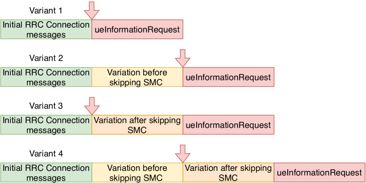
For this example, we consider =the privacy attack on the RLF report [56]. In its canonical form, this attack happens in a session when a device responds with the RLF report message in plaintext due to an unprotected message sent by the adversary before establishing a security context (i.e., before receiving and sending ). example variants of this -undesired-behavior-session is shown in Figure 5. These different variations differ in what messages were sent before and after to the exclusion of the and messages. Variant , the canonical session, does not introduce any messages before or after skipping the Security Mode procedure and just sends the unprotected message to induce the device to respond with an unprotected RLF report message. Variant introduces a variation prior to the skipping of the Security Mode procedure (e.g., sending an identity request message). Variant introduces a variation after the skipping of the Security Mode procedure, possibly by inquiring about the UE’s capabilities through the message, before the plaintext is sent by the adversary. Variant combines both Variants and .
7.3.2 Benign Trace Dataset
To obtain benign traces, we use the MobileInsight [41] crowd-sourced database. This database consists of log files captured by the MobileInsight app and shared from users across the world; covering numerous devices, networks, and countries. We decide to use this data rather than locally captured benign traces to take into consideration other devices and networks, which we do not have access to. We argue that this gives a better representation as to how well the signatures would generalize in the real world trace, possibly containing benign network failures.
From this dataset, we are able to obtain 1,892 NAS layer traces which contain over 52K messages, and as for RRC, we collect 2,045 RRC layer traces consisting of 1.5M messages. This large discrepancy in the number of messages captured per layer can be attributed to the fact that NAS traffic only serves as the communication between the UE and MME, while RRC is responsible for the communication between the UE and the eNodeB and serves as the backbone for NAS and other layers of the LTE protocol stack.
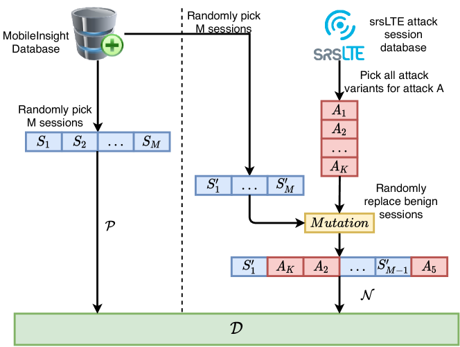
Benign trace generation. We use the collected MobileInsight traces as seed traces and decompose them into individual sessions. In addition to the message types in a session, we also capture relevant predicates from the data (e.g., whether the identity request message warranted IMSI, IMEI, or GUTI). After this step, suppose we have a total of number of sessions. If we want to generate benign traces of length , then we will continue the following process times. At each step, we will randomly pick benign sessions out of total sessions and concatenate them to create a new benign trace. The process is shown on the left of the dotted vertical line in Figure 6. After this process, we will obtain trace skeletons comprising of individual message types and relevant predicates. We then manually convert these trace skeletons to actual replayable benign traces by choosing standard-compliant field values feasible in the testbed while respecting the different predicates. As an example, if the benign trace skeleton in a session contained identity request with IMEI predicate, then we will create a concrete packet reflecting that choice.
7.3.3 Generating Malicious Traces
A massive challenge with evaluating the effectiveness of Phoenix is the fact that no pre-existing repository of vulnerable traces exists. To overcome this, we propose the generation of possibly malicious traces as shown in Figure 6. The trace generation has the following four steps. (❶) The process starts with the manual implementation of all the attacks (and, their -undesired-behavior-session variants) as listed in Table 2. For doing so, following the prior work [38, 56, 32, 31, 50, 45] we changed srsENB and srsEPC libraries in srsLTE [27] to set up the rogue base station. To collect the traces from the UE’s perspective, we utilize SCAT [30]. (❷) Once we have collected the concrete traces, we create skeletons of these traces akin to to the benign trace generation process (i.e., capturing message types and relevant predicates). After this process, for each attack, suppose we have skeletons for -undesired-behavior-session variants. (❸) Suppose we want to generate possibly malicious traces of length for a given attack. We will execute the following step times. At each step, we will first generate a benign trace skeleton of length using the procedure discussed above. Then, we randomly choose attack variants out of (i.e., ) and randomly replace of the benign sessions of with the attack sessions to generate a possibly malicious trace skeleton (see Figure 6). (❹) For generating a concrete replayable malicious trace from a trace skeleton is a manual process and attack-specific. Converting malicious trace skeletons to concrete traces require adding standard-compliant field values while respecting the captured predicates.
Discussion.
Note that, all variants generated by the above process do not necessarily entail an exploitable attack. This is not a limitation because the monitor has to be oblivious to whether a device is susceptible to an attack or not, and instead should raise a warning irrespectively whenever it detects an attack attempt. Taking the privacy attack on the RLF report as an example, the monitor should raise a warning whenever it receives an unprotected message before a security context is established without waiting for the device to respond with an RLF report. For our evaluation, malicious traces that do not induce an attack are acceptable as long as the trace contains an attack attempt. All variants can be found on the following webpage [5].
| Attack | Paper | Layer | # of Variations | Implication |
| AKA Bypass | [38] | 🌑 | 18 | Eavesdropping |
| Measurement Report | [56] | 🌑 | 26 | Location Tracking |
| RLF Report | [56] | 🌑 | 21 | Location Tracking |
| IMSI Cracking | [32] | 🌑 | 2 | Information Leak |
| Paging with IMSI | [32] | 🌑 | 2 | Information Leak |
| Attach Reject | [56] | 🌕 | 4 | Denial of Service |
| Authentication Failure | [31] | 🌕 | 25 | Denial of Service |
| EMM Information | [50] | 🌕 | 32 | Spoofing |
| IMEI Catching | [1] | 🌕 | 2 | Information Leak |
| IMSI Catching | [1] | 🌕 | 2 | Information Leak |
| Malformed Identity Request | [45] | 🌕 | 2 | Information Leak |
| Null Encryption | [1] | 🌕 | 49 | Eavesdropping |
| Numb Attack | [31] | 🌕 | 2 | Denial of Service |
| Service Reject | [56] | 🌕 | 14 | Denial of Service |
| TAU Reject | [56] | 🌕 | 6 | Denial of Service |
8 Evaluation Results of Phoenix
In this section, we discuss the evaluation results for both the signature synthesizer and monitor components. In order to evaluate Phoenix as both a warning system and defense mechanism, we evaluate these two different implementations separately. Due to space constraints, we report the results for 5 attacks here and the rest can be found in the Appendix.
8.1 Signature Synthesizer Evaluation
We evaluate our signature synthesizers based on the research questions discussed in Section 7.1.
Effectiveness of generated signatures ().
For evaluating the effectiveness of the synthesized signatures, we replay the set of testing traces to a device running Phoenix in our testbed (set up with srsLTE [27] and USRP [12]), and measure precision, recall, and F1 score for identifying those vulnerability signatures at runtime.
| Attack | Monitor | Precision | Recall | F1 |
| AKA Bypass | PLTL | 1 | 1 | 1 |
| DFA | 1 | 0.95 | 0.97 | |
| MM | 1 | 1 | 1 | |
| IMSI Cracking | PLTL | 1 | 1 | 1 |
| DFA | 1 | 1 | 1 | |
| MM | 0.67 | 1 | 0.80 | |
| Measurement Report | PLTL | 1 | 1 | 1 |
| DFA | 0.95 | 0.83 | 0.89 | |
| MM | 1 | 1 | 1 | |
| Numb Attack | PLTL | 1 | 1 | 1 |
| DFA | 1 | 1 | 1 | |
| MM | 1 | 1 | 1 | |
| RLF Report | PLTL | 1 | 1 | 1 |
| DFA | 0.83 | 0.64 | 0.72 | |
| MM | 1 | 1 | 1 |
Table 3 presents the precision, recall and F1 score achieved by our signature synthesizers for identifying different attacks at runtime. The signatures used in this experiment were generated with traces for DFA and Mealy Machine, and up for PLTL due to the synthesizer timing out. The figure demonstrates that all of the approaches were able to identify the existing attacks with a high degree of success. Among the different synthesizers, DFA, however, produced a higher number of false positives (21.5%) and false negatives (17.1%) on average whereas Mealy Machine and PLTL turn out to be more reliable; producing a significantly less number of false positives ( 0.03%) and false negatives ( 0.01%).
The perfect F1 score for PLTL across different attacks can be attributed to the fact that these control-plane attacks have a highly discernible signature, which can be seen as the temporal property which all variants of the attacks violate. For instance, the signature synthesized for the RLF Report Attack [56] is the following: . Since this signature precisely describes the behavior of the attack, regardless of the variant, it enables Phoenix to detect the attack with a perfect F1 score.
Another interesting result shown in Table 3 is that Mealy Machine based monitor outperforms the DFA based one in the majority of the cases. This is because DFA learns only on up to 2,500 traces for an individual attack whereas Mealy Machine learns from all the attack traces (2,500 * 15) and therefore has more information to learn from.
Scalability ().
We primarily consider signature learning time as an effective and indirect indicator to the scalability of the corresponding signature synthesizer. The lower the learning time, the higher the scalability. That signifies that scalability time is inversely proportional to the signature learning time. Therefore, to evaluate the scalability of the three proposed signature synthesizers (DFA, MM, and PLTL), we vary the sample size of the training sets to 50, 100, 250, 500, 1250, and 2500, and measure the learning time required by a synthesizer for each of the attacks. Figure 7 presents the results of this evaluation in which the Y-axis is seconds in the logarithmic scale and the X-axis is the training dataset size.
Figure 7 shows that our PLTL signature synthesizer takes considerably more time to synthesize a signature as compared to DFA and MM synthesizers. This large discrepancy can be attributed to the fact that the PLTL synthesizer is a search based algorithm. The search space grows very quickly as the depth of the abstract syntaxt tree (AST) increases. On the other hand, RPNI [48] proves to scale quite well because RPNI is a polynomial time algorithm while SAT is NP-Complete. For instance, training the AKA Bypass [38] attack with PLTL synthesizer takes a significantly higher amount of time than others. Though PLTL synthesizer for AKA Bypass attack quickly times out, the same synthesizer does not time out for other attacks, such as the Numb Attack [31] until it reaches traces. This is due to the much deeper AST for AKA Bypass PLTL signature than that for the Numb Attack.
Impact of training set size on signature quality ().
Since real-life cellular attack traces are difficult to obtain, we aim at evaluating whether or not more training data generate a higher quality signature. We consider a high quality signature as one that achieves a perfect F1 score. In other words, F1 score and signature quality are proportional to each other. To evaluate this, we vary the size of the training datasets and measure the synthesizers’ effectiveness at detecting the attacks.
Figure 8 shows that all three signature synthesizers achieve high F1 score when training on 500 traces, with the exception of AKA Bypass for DFA, which goes down as more training data is given. As the RPNI learning process is highly dependent on the exact set of input traces, this discrepancy can be attributed to the variability of the input traces. Note that, our PLTL signature synthesizer achieves a perfect F1 score across all attacks, regardless of the training dataset size, because of its usage of exhaustive search to learn a precise but highly generalizable signature.
Since the PLTL synthesizer is able to produce a highly generalizable signature regardless of the training dataset in the previous experiment, we decide to analyze this further by discovering the minimum attack traces required to generate a high quality signature. We consider a high quality signature is one that achieves a perfect F1 score. To perform this experiment, we fix the benign traces to and vary the number of attack traces from to . The results can be found in Table 4. These results show that the PLTL synthesizer can rapidly produce a high quality signature. Both the RLF Report and Measurement Report privacy attacks prove to require a larger number of attack traces. This can be attributed to the fact that these signatures are more complex than others, with the exception of the AKA Bypass attack, however, more variants exist.
These results show that the PLTL synthesizer can rapidly produce a high quality signature. Another observation that is obvious is the fact that Measurement Report and RLF Report require more attack traces than others. This can be attributed to a couple of reasons. The first reason behind this result, is that these two attacks require a larger search space since the alphabet is bigger than the others. The second reason is that these attacks are more complex than others, with the exception of the AKA Bypass attack which can be seen as a stepping stone for both. In addition, these results can also attributed to the fact that our PLTL synthesizer blindly searches for solutions instead of using the given traces to narrow down the search space.
| Attack | Minimum Attack Trace | # of Variations |
| AKA Bypass | 3 | 2 |
| IMSI Cracking | 1 | 1 |
| Measurement Report | 11 | 5 |
| RLF Report | 8 | 2 |
| Numb Attack | 3 | 2 |
Signature Synthesizer Evaluation Conclusion.
The PLTL synthesizer proved to not scale as well as RPNI [48] based approaches, however, it proved to quickly generated highly generalizable signature. In fact, such a signature generation with a minimal number of traces is critical since generating attack traces is a challenging task for cellular networks. Therefore, we conclude that the PLTL synthesizer outperforms the RPNI [48] approaches.
8.2 Monitor Evaluation (Warning System)
In this subsection, we answer the research questions driving the evaluation of three different monitoring approaches (i.e., PLTL, DFA, and Mealy Machine) when considering a warning system instantiation.
Efficiency ().
One of the key factors in identifying the best monitor instantiation is the number of messages each monitor can process per second. For this, we perform a stress test by mimicking the modem through the replaying of real traces captured from MobileInsight’s database [41] without any delay between subsequent messages. We measure how long each monitor takes to process and check for the presence of an attack by consulting its entire signature database. Table 6 summarizes the processing speed (messages/second) of different devices for different monitoring approaches running in two different layers (RRC and NAS). In addition to this, we computed the CPU cycles required per call to the monitor component for each device which can be found in Table 5.
| Layer | Monitor | Device | Avg. CPU Cycles |
| RRC | DFA | Pixel 3 | 54,127.20 |
| Nexus 6P | 97,168.98 | ||
| Nexus 6 | 325,579.71 | ||
| PLTL | Pixel 3 | 384,282.80 | |
| Nexus 6P | 560,255.48 | ||
| Nexus 6 | 4,065,040.65 | ||
| MM | Pixel 3 | 7,177.05 | |
| Nexus 6P | 15,900.18 | ||
| Nexus 6 | 78,850.07 | ||
| NAS | DFA | Pixel 3 | 81,957.62 |
| Nexus 6P | 136,431.23 | ||
| Nexus 6 | 599,973.33 | ||
| PLTL | Pixel 3 | 742,528.31 | |
| Nexus 6P | 1,094,331.36 | ||
| Nexus 6 | 4,456,180.89 | ||
| MM | Pixel 3 | 7,586.85 | |
| Nexus 6P | 14,812.58 | ||
| Nexus 6 | 78,853.99 |
As shown in Table 6, across all three devices, Mealy Machine can process multiple orders of magnitude higher messages per second than the other two monitoring approaches. This can be attributed to the fact that Mealy Machine keeps only a single internal state per layer, as compared to 10 internal states for NAS and 5 for RRC. Moreover, Mealy Machine relies on a single dictionary lookup to decide on the transition and whether to flag a trace as an attack. Similar to Mealy Machine, DFA can also process messages at a much faster rate than PLTL. This is because the DFA also relies on a simple dictionary lookup similar to Mealy Machine for a single signature. On the other hand, PLTL requires the evaluation of logical and temporal operators to classify the incoming traces which is a more expensive operation.
To put our results in perspective, we compare it with real traces. We compute the mean, median, standard deviation, and maximum number of messages of real NAS and RRC traces obtained from the MobileInsight database [41]. We observe that on average, there were 0.02 messages per second for NAS traffic (median=0.011, standard deviation=0.069, maximum=0.8), and 0.2 messages per second (median=0.122, standard deviation=0.273, maximum=2.76) for RRC traffic.
In summary, our slowest monitor (i.e., PLTL) can handle substantially more message per second than the NAS and RRC traffic we observed in real traces.
| Layer | Monitor | Device | Avg. | SD |
| RRC | DFA | Pixel 3 | 51730.6 | 158596.4 |
| Nexus 6P | 20582.7 | 73663.6 | ||
| Nexus 6 | 8292.9 | 8636.4 | ||
| PLTL | Pixel 3 | 7286.3 | 55599.5 | |
| Nexus 6P | 3569.8 | 12976.3 | ||
| Nexus 6 | 664.2 | 58.0 | ||
| MM | Pixel 3 | 390132.6 | 790596.7 | |
| Nexus 6P | 125784.7 | 359847.7 | ||
| Nexus 6 | 34242.2 | 14377.8 | ||
| NAS | DFA | Pixel 3 | 34164.0 | 224904.7 |
| Nexus 6P | 14659.4 | 110780.6 | ||
| Nexus 6 | 4500.2 | 4170.7 | ||
| PLTL | Pixel 3 | 3770.9 | 62512.7 | |
| Nexus 6P | 1827.6 | 22226.2 | ||
| Nexus 6 | 605.9 | 1472.4 | ||
| MM | Pixel 3 | 369059.5 | 723754.8 | |
| Nexus 6P | 135020.4 | 371327.7 | ||
| Nexus 6 | 34240.5 | 20397.0 |
Energy Consumption ().
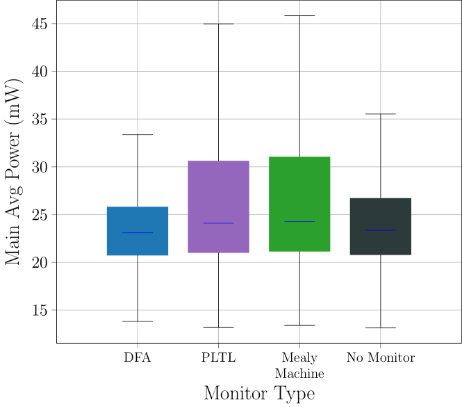
To understand the energy consumption induced by each monitor component, we measure the battery consumption induced by Phoenix. We perform this experiment by connecting the Nexus 6 to a Monsoon Meter [4]. The Nexus 6, unlike the other two devices, has a removable back which makes it easier to connect to the power meter. In this experiment, the traffic is simulated to avoid the noise induced by the cellular connection. In addition to the radio, we switch off the screen, Bluetooth, and Wi-Fi. We then invoke each monitor with messages to evaluate the average power consumption. Figure 9 presents the average power consumption by three different monitors along with the case when no monitor is active. The results match the trend with that of synthesizers’ effectiveness, except for the fact that Mealy Machine consumed slightly more electricity than PLTL and DFA, respectively. This discrepancy could be attributed to the fact that even though we disabled many power hungry components of the Android system, we have no control as to what other applications in the device are doing. Overall though, all monitors add negligible overhead.
Real World Evaluation ().
Vulnerability detection systems must balance false warnings with effectiveness. If the user is bombarded with false warnings, the user would disable the system in order to prevent continuously erroneous warnings. In light of this, we aim to uncover how many warnings each different monitor produces and the type of them. To carry out this experiment, we deploy Phoenix on two Pixel 3 devices running on four major U.S. cellular network carriers on two different geographical areas. In this experiment, we run Phoenix for approximately 12 hours and use the Pixel 3 as our daily devices, which includes driving approximately 10 miles. The results are shown in Table 7. As expected by previous results, DFA proves to be inadequate and produces a larger amount of false warnings. We inspect each warning and uncover that the DFA signature does not take into consideration the behavior seen by these real networks. On the other hand, Mealy Machine produces no false warnings and therefore would not bombard the user with these. Notably, PLTL produces one warning on three different providers, specifically the warning that is triggered when the EMM Information message is sent in plaintext. After manual inspection, we discover that these in fact are not false warnings, but misconfigurations by these three providers.
| US-1 | US-2 | US-3 | US-4 | |
| DFA | 6✗ | 7✗ | 4✗ | 4✗ |
| PLTL | 0 | 1✓ | 1✓ | 1✓ |
| MM | 0 | 0 | 0 | 0 |
Evaluation Summary of Warning System Instantiation.
Mealy Machine proved to be highly efficient, however, all three monitors were able to parse a significantly high number of messages per second to not induce any delay at runtime. We then measured power consumption and discovered that all three monitors are highly efficient by imposing a negligible overhead. We then carried out a real world evaluation of Phoenix by deploying it on cellular devices with real SIM cards and uncover that PLTL and Mealy Machine produce no false warnings, and in fact, PLTL uncovers real misconfigurations in three of the major U.S. cellular network carriers. In summary, PLTL proved to be the monitor component that best satisfies the core requirements.
8.3 Monitor Evaluation (Defense Mechanism)
Understanding the requirements of Phoenix when implemented in the baseband is crucial in order to understand its deployability. Due to this, this subsection answers the research questions driving the evaluation of the baseband instantiation of Phoenix. We perform these experiments on the baseband implementation as discussed in Section 6.1. Due to the fact that PLTL is the monitor that performed the best as shown previously (in Section 8.2), we focus on the PLTL monitor.
Memory overhead in baseband ().
Low memory overhead is critical in order for a defense mechanism to be feasible. To analyze this overhead, we measure the memory using the time Linux command capable of extracting the maximum resident set size. We then compare the implementation of Phoenix in srUE (dubbed ) and the vanilla version of srsUE (dubbed ). To perform this experiment, we connect the srsUE implementations 100 times to the eNodeB and EPC by running the corresponding components of srsLTE [27] on a secondary machine.
Figure 10 shows the distribution of both srsUE implementations. The distribution is similar in both implementations. The mean difference is only 159.25 KB. To put this result in perspective, on average consumes approximately 370MB, therefore, Phoenix induces only a mere overhead. Overall, we demonstrate that memory overhead of Phoenix is not a major concern in its baseband instantiation.
Computational overhead in baseband ().
Another key point that must be analyzed is the computational overhead imposed by Phoenix in a baseband implementation. This is because any substantial delay imposed by Phoenix could affect the quality of service and result in a disruption of service. In this experiment, we run the baseband implementation of Phoenix running all the monitors and measuring the time it takes for all monitors to run sequentially by measuring the system time in microseconds with the getrusage c++ function. We carried out this experiment connecting the modified version of srsUE 100 times to an eNodeB and EPC running on a secondary machine. On average, calling all 15 monitors sequentially added an overhead of microseconds, with a standard deviation of . Overall, this experiment verifies that the overhead induced by Phoenix is negligible, and would unlikely to induce any QoS or service disruption issues.
Evaluation Summary of Baseband Implementation.
We evaluated the overhead induced by the baseband implementation of Phoenix in srsUE to serve as a proxy to understand the real world requirements. Phoenix showed to require minimal memory ( kbytes) and computational overhead ( microseconds) which shows that Phoenix could be deployed in a real baseband implementation.
9 Discussion
We now discuss different salient aspects of Phoenix.
Impacts of the attacks identified by Phoenix.
One of the questions that may come up is to ask how prevalent are the different attacks and unsafe practices identified by Phoenix. Unfortunately, there are no public quantitative data on the attack prevalence. We have seen anecdotal evidence of some attacks and unsafe practices in the literature. For instance, until two years ago, one of the major US network operator did not use encryption to protect their control-plane traffic. Another major US operator used a persistent identifier in paging messages even though this is discouraged. In addition, bidding down attacks are pretty commonplace as warned by many media outlets and even Senators. We envision that Phoenix can enable more awareness on the security issues of cellular network and protect users from such attacks. A possible instantiation of PHOENIX is to be deployed as cellular network probes or honey pots that can log protocol sessions with undesired behavior in order to perform statistical measurements, and in fact, its application based instantiation has helped uncover unsafe practices on three major U.S. cellular network providers.
Android and Qualcomm chipsets.
Our current implementation of Phoenix supports Qualcomm baseband processors running on Android. We focus on Android not only because it is the most popular mobile OS but also it allows one to expose the cellular interface in the debug mode with root access. We envision that OSes can expose the modem information by requesting the permission from the user similar to how other high privilege permissions can be granted to user level applications. Additionally, in the future we aim to extend this for other OSes and baseband processors [30].
Phoenix deployed as an Android Application.
Phoenix’s application instantiation is developed on top of MobileInsight which is written in Python. This requires a python interpreter to be installed in Android. Even then Phoenix has shown its effectiveness without incurring a substantial overhead. Going forward, however, writing the core functionality of Phoenix in C/C++ will not only positively impact the performance but also the battery life of the device.
Supporting other protocol versions and device-specific attacks.
Phoenix is currently instantiated only for 4G LTE. Support of prior protocol versions (i.e., 2G/3G) and upcoming versions (i.e., 5G) can be effortlessly added in the current instantiation by enhancing the current parsing functionality of Phoenix to include 2G, 3G, and 5G protocol packets. In addition, signatures for device-specific attacks, due to implementation bugs in a device, can be supported by the current version of Phoenix without any change.
User Study.
To be effective as a warning system, it is paramount to ensure that warning messages Phoenix generates convey the right information regarding the warning. Performing a user study with different warning designs is one of the effective ways of obtaining some assurances on the efficacy of the warning messages. To limit the scope of the paper to only the technical design of Phoenix, we leave the user study as future work.
False positives and the quality of signatures.
The quality of synthesized signatures used in the empirical evaluation of this paper heavily relies on the diversity of malicious traces used during training. Having very similar malicious traces in training will likely induce the synthesizer to come up with a non-generalized behavioral signature that will only be effective in detecting undesired behavior similar to the ones observed in the malicious training traces and possibly, a few of its variants. Such a non-generalized signature, however, is unlikely to capture other diverse variants of the undesired behavior in question that are not present in the malicious training traces. This is because the synthesized signatures only guarantee observationally consistency, that is, the synthesized signatures will not make any mistakes in correctly classifying the sample traces given to it during training. Not having diverse malicious traces during synthesis can thus induce a signature that incurs false positives. In addition to this situation, false positives can also be incurred due to having only coarse-grained information on the training traces (i.e., lacking fine-grained information).
Let us consider the downgrade attack through fabricated message as an example [56]. In this attack, the adversary establishes a malicious base station which emits a higher signal strength and then lures the victim device into connecting to the malicious base station. Then, the adversary during the mutual authentication of the attach procedure injects a fabricated message, resulting in the device to downgrade to an insecure protocol version (e.g., moving from 4G LTE to 3G). Just by observing the temporal ordering of events, without taking into consideration the migration of the device from 4G LTE to 3G, the best possible signature a synthesizer can come up with is the existence of the message. Such a signature may induce false positives because messages can be sent by the network in benign situations.
In our experiments, due to random selection of benign sessions from real-life traces and messages being rare, none of the benign traces during training had any messages, whereas all the negative traces at least had one. As a result, the synthesizer rightfully came up with a signature saying an existence of the message is an attack, especially because this is the smallest signature that is observationally consistent. Due to our session-level trace generation approach discussed before, we did not have faithful information about the downgrade of the protocol version. Even if we had that precise information as part of the training traces, the synthesizer will give us a precise signature according to which the monitor will identify the attack only when the connection downgrade has already happened instead of before protocol version downgrade happens. We argue that a proactive monitor, which notifies the user as soon as an message has occurred instead of waiting for a downgrade, is more effective in protecting the user even at the cost of a few false positives. Since messages are indeed rare in practice, corroborated by the MobileInsight traffic, such a trade-off is a reasonable choice.
Alternate approaches.
One alternate method for in-device monitoring of cellular traffic for attack detection is to construct a state machine representing the desired cellular protocol behavior from the 3GPP standard specification [2, 3]. At runtime, one could then flag any state transitions that are not allowed by this reference state machine as potential attacks. Such an approach, however, suffers from the following limitations: (1) Manually constructing the protocol state machine by reading natural languages specification is an error-prone and time-consuming ordeal; (2) The abstract protocol state machine given by the standard specification is not always prescriptive, leaving aspects to be decided by implementors; (3) Not all deviant state transitions necessarily signify an attack and thus can induce a high number of false warnings.
In another approach, one may consider manually writing one small program for each attack using simple if-then-else constructs that checks for a certain attack in the trace. The attacks we consider here, however, would require storing memory and would require intensive manual effort to identify the portion of the traces that need to be stored. In contrast, our approach is completely automated in figuring out what portion of the history to store for careful attack identification without requiring human intervention. Such automation comes in handy when new attacks are discovered and their signatures need to be deployed promptly.
10 Related Work
Runtime Monitors.
Extensive work has been done in developing efficient runtime monitors using different types of logic [15, 16, 17, 18, 19, 20, 25, 53, 57, 22]. However, all but [57, 22] attempt to create a deployable system which tries to apply runtime monitoring to web protocols. In contrast, Phoenix aims to be a deployable system, similar to [57, 22], however, we apply runtime monitoring to 4G LTE cellular networks. In addition, we apply three different runtime monitor approaches while [57, 22] only rely on automata based approaches. Phoenix not only serves as the runtime monitor but also provide the learning component to generate signatures, including PLTL formulas.
Anomaly Detection in Cellular Devices.
Some work has been done to detect anomalies in cellular networks within the cellular device, precisely to discover the presence of fake base stations proposed by Dabrowski et al. [23]. In addition, multiple apps have attempted to enable the detection of fake base stations using an application, but unfortunately do not generalize well [49]. In contrast to these attempts at anomaly detection, Phoenix looks for specific patterns of message flow to detect specific attacks and provide a possible remedy.
Modification of Protocol.
Another approach researchers have leveraged to provide a defense mechanism is the modification of the protocol, such as in [36, 6, 35, 58, 34]. Out of these works, only [34] provides a wide array of coverage while the others mainly focus on the IMSI catching attack. In contrast to other work, Phoenix is the first warning system for cellular networks that provides the device more intelligence about other components of the network by only relying on message flows.
11 Conclusion
In this paper, we develop Phoenix, a general approach which can efficiently monitor a device’s cellular network traffic and identify the presence of attacks. We achieve this by instantiating two different implementations of PHOENIX: a runtime monitor within an Android application, allowing the cellular device to reason about malicious message flow and alert the user; A modified version of srsUE [27] powered by a runtime monitor allowing it to detect vulnerabilities and prevent potential undesired behavior.
Overall we observe that our best approach with PLTL can correctly identify all the 15 n-day 4G LTE attacks and unsafe practices used in the evaluation section with a high packet processing speed (68000 packets/second), while inducing a moderate energy (4mW) and negligible memory overhead () on the device.
Acknowledgment
We thank the anonymous reviewers for their valuable suggestions. This work was funded by DARPA YFA contract no. D19AP00039. The views and conclusions contained herein are those of the authors and should not be interpreted as necessarily representing the official policies or endorsements of DARPA.
References
- [1] 3GPP. Non-Access-Stratum (NAS) protocol for Evolved Packet System (EPS); Stage 3 Specification 3GPP TS 24.301 version 12.8.0 Release 12., [Online]. Available: http://www.3gpp.org/dynareport/24301.htm.
- [2] 3GPP Standard, www.3gpp.org.
- [3] 3GPP Standard. Release 12., http://www.3gpp.org/specifications/releases/68-release-12.
- [4] Monsoon Power Meter, https://wwww.msoon.com/LabEquipment/PowerMonitor/.
- [5] Phoenix, https://phoenixlte.github.io/.
- [6] Protecting IMSI and User Privacy in 5G Networks, www.ericsson.com/res/docs/2016/protecting-imsi-and-user-privacy-in-5g-networks.pdf.
- [7] python-for-android, https://python-for-android.readthedocs.io/en/latest/.
- [8] Python’s GIL - A Hurdle to Multithreaded Program, https://medium.com/python-features/pythons-gil-a-hurdle-to-multithreaded-program-d04ad9c1a63.
- [9] Qualcomm Snapdragon 845 Mobile Platform, https://www.qualcomm.com/media/documents/files/snapdragon-845-mobile-platform-product-brief.pdf.
- [10] Qualcomm Snapdragon 845 Mobile Platform, https://www.qualcomm.com/system/files/document/files/snapdragon_product_brief_810_0.pdf.
- [11] Qualcomm Snapdragon 845 Mobile Platform, https://www.qualcomm.com/media/documents/files/snapdragon-805-processor-product-brief.pdf.
- [12] USRP B210, https://www.ettus.com/product/details/UB210-KIT.
- [13] C. Barrett, A. Stump, C. Tinelli et al., “The smt-lib standard: Version 2.0,” in Proceedings of the 8th international workshop on satisfiability modulo theories (Edinburgh, England), vol. 13, 2010, p. 14.
- [14] D. Basin, J. Dreier, L. Hirschi, S. Radomirovic, R. Sasse, and V. Stettler, “A formal analysis of 5g authentication,” in Proceedings of the 2018 ACM SIGSAC Conference on Computer and Communications Security, ser. CCS ’18. New York, NY, USA: ACM, 2018, pp. 1383–1396. [Online]. Available: http://doi.acm.org/10.1145/3243734.3243846
- [15] D. Basin, F. Klaedtke, and S. Müller, “Monitoring security policies with metric first-order temporal logic,” in Proceedings of the 15th ACM symposium on Access control models and technologies, 2010, pp. 23–34.
- [16] ——, “Policy monitoring in first-order temporal logic,” in International Conference on Computer Aided Verification. Springer, 2010, pp. 1–18.
- [17] D. Basin, F. Klaedtke, S. Müller, and B. Pfitzmann, “Runtime monitoring of metric first-order temporal properties,” in IARCS Annual Conference on Foundations of Software Technology and Theoretical Computer Science. Schloss Dagstuhl-Leibniz-Zentrum für Informatik, 2008.
- [18] D. Basin, F. Klaedtke, S. Müller, and E. Zălinescu, “Monitoring metric first-order temporal properties,” Journal of the ACM (JACM), vol. 62, no. 2, pp. 1–45, 2015.
- [19] D. A. Basin, F. Klaedtke, and E. Zalinescu, “The MonPoly monitoring tool.” RV-CuBES, vol. 3, pp. 19–28, 2017.
- [20] A. Bauer, M. Leucker, and C. Schallhart, “Runtime verification for ltl and tltl,” ACM Transactions on Software Engineering and Methodology (TOSEM), vol. 20, no. 4, pp. 1–64, 2011.
- [21] M. Benedetti and A. Cimatti, “Bounded model checking for past ltl,” in International Conference on Tools and Algorithms for the Construction and Analysis of Systems. Springer, 2003, pp. 18–33.
- [22] S. Calzavara, R. Focardi, M. Maffei, C. Schneidewind, M. Squarcina, and M. Tempesta, “WPSE: Fortifying web protocols via browser-side security monitoring,” in 27th USENIX Security Symposium ( Security 18), 2018, pp. 1493–1510.
- [23] A. Dabrowski, N. Pianta, T. Klepp, M. Mulazzani, and E. Weippl, “Imsi-catch me if you can: Imsi-catcher-catchers,” in Proceedings of the 30th Annual Computer Security Applications Conference, ser. ACSAC ’14, 2014, pp. 246–255.
- [24] C. De la Higuera, Grammatical inference: learning automata and grammars. Cambridge University Press, 2010.
- [25] X. Du, Y. Liu, and A. Tiu, “Trace-length independent runtime monitoring of quantitative policies in ltl,” in International Symposium on Formal Methods. Springer, 2015, pp. 231–247.
- [26] M. d’Amorim and G. Roşu, “Efficient monitoring of -languages,” in International Conference on Computer Aided Verification. Springer, 2005, pp. 364–378.
- [27] I. Gomez-Miguelez, A. Garcia-Saavedra, P. D. Sutton, P. Serrano, C. Cano, and D. J. Leith, “srsLTE: an open-source platform for lte evolution and experimentation,” in Proceedings of the Tenth ACM International Workshop on Wireless Network Testbeds, Experimental Evaluation, and Characterization. ACM, 2016, pp. 25–32.
- [28] L. H., “LTE redirection: Forcing targeted lte cellphone into unsafe networks,” in Hack in the Box Security Conference (HITBSec-Conf), 2016.
- [29] K. Havelund and G. Roşu, “Efficient monitoring of safety properties,” International Journal on Software Tools for Technology Transfer, vol. 6, no. 2, pp. 158–173, 2004.
- [30] B. Hong, S. Park, H. Kim, D. Kim, H. Hong, H. Choi, J.-P. Seifert, S.-J. Lee, and Y. Kim, “Peeking over the cellular walled gardens-a method for closed network diagnosis,” IEEE Transactions on Mobile Computing, vol. 17, no. 10, pp. 2366–2380, 2018.
- [31] S. R. Hussain, O. Chowdhury, S. Mehnaz, and E. Bertino, “Lteinspector: A systematic approach for adversarial testing of 4g lte,” in 25th Annual Network and Distributed System Security Symposium, NDSS, San Diego, CA, USA, February 18-21, 2018.
- [32] S. R. Hussain, M. Echeverria, O. Chowdhury, N. Li, and E. Bertino, “Privacy attacks to the 4g and 5g cellular paging protocols using side channel information,” in 26th Annual Network and Distributed System Security Symposium, NDSS, San Diego, CA, USA, February 24-27, 2019, 2019.
- [33] S. R. Hussain, M. Echeverria, I. Karim, O. Chowdhury, N. Li, and E. Bertino, “5GReasoner: A property-directed security and privacy analysis framework for 5g cellular network protocol,” in Proceedings of the 26th ACM SIGSAC Conference of Computer and Communications Security. ACM, 2019.
- [34] S. R. Hussain, M. Echeverria, A. Singla, O. Chowdhury, and E. Bertino, “Insecure connection bootstrapping in cellular networks: the root of all evil,” in Proceedings of the 12th Conference on Security and Privacy in Wireless and Mobile Networks. ACM, 2019, pp. 1–11.
- [35] M. S. A. Khan and C. J. Mitchell, “Trashing imsi catchers in mobile networks,” in Proceedings of the 10th ACM Conference on Security and Privacy in Wireless and Mobile Networks, 2017, pp. 207–218.
- [36] M. Khan and V. Niemi, “Concealing imsi in 5g network using identity based encryption,” in axXiv preprint arXiv:1708.01868, 2017.
- [37] B. Kim, S. Bae, and Y. Kim, “Guti reallocation demystified: Cellular location tracking with changing temporary identifier,” in 25th Annual Network and Distributed System Security Symposium, NDSS, San Diego, CA, USA, February 18-21, 2018.
- [38] H. Kim, J. Lee, L. Eunkyu, and Y. Kim, “Touching the Untouchables: Dynamic Security Analysis of the LTE Control Plane,” in Proceedings of the IEEE Symposium on Security & Privacy (SP). IEEE, May 2019.
- [39] K. Kohls, D. Rupprecht, T. Holz, and C. Pöpper, “Lost traffic encryption: Fingerprinting lte/4g traffic on layer two,” 2019.
- [40] S. Kripke, “Semantical Considerations on Modal Logic,” Acta Phil. Fennica, vol. 16, pp. 83–94, 1963.
- [41] Y. Li, C. Peng, Z. Yuan, J. Li, H. Deng, and T. Wang, “Mobileinsight: Extracting and analyzing cellular network information on smartphones,” in Proceedings of the 22nd Annual International Conference on Mobile Computing and Networking, ser. MobiCom ’16. New York, NY, USA: ACM, 2016, pp. 202–215.
- [42] Z. Li, W. Wang, C. Wilson, J. Chen, Q. Chen, T. Jung, L. Zhang, K. Liu, X. Li, and Y. Liu, “Fbs-radar: Uncovering fake base stations at scale in the wild,” in 24th Annual Network and Distributed System Security Symposium, NDSS, San Diego, CA, USA, 2017.
- [43] O. Lichtenstein, A. Pnueli, and L. Zuck, “The glory of the past,” in Workshop on Logic of Programs. Springer, 1985, pp. 196–218.
- [44] G. H. Mealy, “A method for synthesizing sequential circuits,” The Bell System Technical Journal, vol. 34, no. 5, pp. 1045–1079, 1955.
- [45] B. Michau and C. Devine, “How to not break lte crypto,” in ANSSI Symposium sur la sécurité des technologies de l’information et des communications (SSTIC), 2016.
- [46] D. Neider and I. Gavran, “Learning linear temporal properties,” in 2018 Formal Methods in Computer Aided Design (FMCAD). IEEE, 2018, pp. 1–10.
- [47] K. Nohl, “Mobile self-defense.” [Online]. Available: https://events.ccc.de/congress/2014/Fahrplan/system/attachments/2493/original/Mobile_Self_Defense-Karsten_Nohl-31C3-v1.pdf
- [48] J. Oncina and P. Garcia, “Inferring regular languages in polynomial updated time,” in Pattern recognition and image analysis: selected papers from the IVth Spanish Symposium. World Scientific, 1992, pp. 49–61.
- [49] S. Park, A. Shaik, R. Borgaonkar, A. Martin, and J.-P. Seifert, “White-stingray: Evaluating IMSI catchers detection applications,” in 11th USENIX Workshop on Offensive Technologies (WOOT ’17). Vancouver, BC: USENIX Association, 2017. [Online]. Available: https://www.usenix.org/conference/woot17/workshop-program/presentation/park
- [50] S. Park, A. Shaik, R. Borgaonkar, and J.-P. Seifert, “White rabbit in mobile: Effect of unsecured clock source in smartphones,” in Proceedings of the 6th Workshop on Security and Privacy in Smartphones and Mobile Devices. ACM, 2016, pp. 13–21.
- [51] A. Pnueli, “The temporal logic of programs,” in 18th Annual Symposium on Foundations of Computer Science (sfcs 1977). IEEE, 1977, pp. 46–57.
- [52] H. Raffelt, B. Steffen, and T. Berg, “Learnlib: A library for automata learning and experimentation,” in Proceedings of the 10th international workshop on Formal methods for industrial critical systems, 2005, pp. 62–71.
- [53] G. Rosu and K. Havelund, “Synthesizing dynamic programming algorithms from linear temporal logic formulae,” 2001.
- [54] D. Rupprecht, K. Kohls, T. Holz, and C. Pöpper, “Breaking LTE on layer two,” in IEEE Symposium on Security & Privacy (SP). IEEE, May 2019.
- [55] D. Rupprecht, K. Kohls, T. Holz, and C. Pöpper, “Call me maybe: Eavesdropping encrypted LTE calls with revolte,” in 29th USENIX Security Symposium (USENIX Security 20), 2020, pp. 73–88.
- [56] A. Shaik, J. Seifert, R. Borgaonkar, N. Asokan, and V. Niemi, “Practical attacks against privacy and availability in 4g/lte mobile communication systems,” in 23nd Annual Network and Distributed System Security Symposium, NDSS, San Diego, CA, USA, February 21-24, 2016.
- [57] B. Soewito, L. Vespa, A. Mahajan, N. Weng, and H. Wang, “Self-addressable memory-based fsm: a scalable intrusion detection engine,” IEEE network, vol. 23, no. 1, pp. 14–21, 2009.
- [58] F. van den Broek, R. Verdult, and J. de Ruiter, “Defeating imsi catchers,” in Proceedings of the 22Nd ACM SIGSAC Conference on Computer and Communications Security, ser. CCS ’15. ACM, 2015, pp. 340–351.
- [59] Z. Zhuang, X. Ji, T. Zhang, J. Zhang, W. Xu, Z. Li, and Y. Liu, “Fbsleuth: Fake base station forensics via radio frequency fingerprinting,” in Proceedings of the 2018 on Asia Conference on Computer and Communications Security, ser. ASIACCS ’18, 2018, pp. 261–272.
Appendix A Cellular Network Vulnerabilities
In this section, we provide an extensive list of vulnerabilities found on cellular networks. Table 8 shows an extensive list of cellular network attacks uncovered in recent years summarizing which attacks we can detect with the current iteration, could detect with one of the following extensions to Phoenix: 1) Extend the message parser to decode another cellular network generation traffic; 2) Extend the message parser to decode other layer traffic; 3) Add a specific predicate to enable the attack detection, or cannot detect due to one of the following reasons: a) temporal ordering does not serve as a proxy to uncover vulnerable behavior; b) Require statistical information (e.g., number of paging messages received within a given time frame).
| Attack Name | Paper | Layer | Repercussion | Detectable | Cause |
| Authentication Synchronization Failure | [31] | NAS | Denial of Service | 🌑 | ★ |
| Traceability Attack | [31] | NAS | Location Leak | 🌑 | ★ |
| Numb Attack | [31] | NAS | Denial of Service | 🌑 | ★ |
| Paging Channel Hijacking | [31] | RRC | Denial of Service | 🌕 | ★ |
| Stealthy Kicking Off | [31] | RRC | Denial of Service | 🌑 | ★ |
| Panic Attack | [31] | RRC | Artificial Chaos | 🌕 | ★ |
| Energy Depletion Attack | [31] | RRC | Battery Depletion | 🌕 | ★ |
| Linkability Attack | [31] | RRC | Location Leak | 🌑 | ★ |
| Detach / Downgrade Attack | [31] | NAS | Denial of Service / Downgrade | 🌑 | ★ |
| Authentication Relay Attack | [31] | NAS | Location Poisoning | 🌕 | ★ |
| TORPEDO Attack | [32] | RRC | Identifier Leak / Location Leak | 🌕 | ★ |
| IMSI Cracking Attack Against 4G | [32] | RRC | Identifier Leak | 🌑 | ★ |
| IMSI Cracking Attack Against 5G | [32] | NAS | Identifier Leak | ☾ | ★ |
| Social Network to TMSI Mapping | [56] | RRC | Identifier Leak | 🌕 | ★ |
| Link Subscriber Location Movement | [56] | RRC | Location Leak | 🌕 | ★ |
| Leak Coarse Location | [56] | RRC | Location Leak | 🌕 | ★ |
| Measurement Report Location Leak | [56] | RRC | Location Leak | 🌑 | ✩ |
| RLF Report Location Leak | [56] | RRC | Location Leak | 🌑 | ✩ |
| TAU Reject to Disrupt Service | [56] | NAS | Denial of Service | 🌑 | ✩ |
| Service Reject to Disrupt Service | [56] | NAS | Denial of Service | 🌑 | ★ |
| Attach Reject to Disrupt Service | [56] | NAS | Denial of Service | 🌑 | ★ |
| Denying Selected Service with Malicious Attach Request | [56] | NAS | Denial of Service | 🌕 | ★ |
| Counter Reset (Replay) | [33] | NAS (5G) | Denial of Service | ☾ | ★ |
| Counter Reset (Reset) | [33] | NAS (5G) | Denial of Service / Overbilling | ☾ | ★ |
| Uplink NAS Counter Desynchronization | [33] | NAS (5G) | Denial of Service | ☾ | ★ |
| Exposing NAS Sequence Number | [33] | NAS (5G) | Service Profiling | 🌕 | ★ |
| Neutralizing TMSI Refreshment | [33] | NAS (5G) | Location Leak | ☾ | ★ |
| Cutting off the Device | [33] | NAS (5G) | Denial of Service | 🌕 | ★ |
| Denial of Service with RRC Setup Request | [33] | RRC (5G) | Denial of Service | 🌕 | ★ |
| Installing Null Cipher and Null Integrity | [33] | RRC (5G) | Identifier Leak | ☾ | ★ |
| Lullaby Attack | [33] | RRC (5G) | Battery Depletion | 🌕 | ★ |
| Incarceration using RRC messages | [33] | RRC (5G) | Denial of Service | ☾ | ★ |
| Exposing Device’s TMSI and Paging Occasion | [33] | NAS / RRC (5G) | Identifier Leak/ Denial of Service/ Location Leak | 🌕 | ★ |
| Exposing Device’s I-RNTI | [33] | NAS / RRC (5G) | Identifier Leak | 🌕 | ★ |
| Blind DoS Attack | [33] | NAS / RRC (5G) | Denial of Service | 🌕 | ★ |
| AKA Bypass | [38] | RRC | Eavesdropping | 🌑 | ✩ |
| RRC Connection Reestablishment - Unencrypted | [38] | RRC | Denial of Service | 🌑 | ✩ |
| RRC Connection Reconfiguration - Unencrypted | [38] | RRC | Eavesdropping / Location Leak | 🌑 | ✩ |
| RRC Connection Reestablishment Reject - Unencrypted | [38] | RRC | Denial of Service | 🌑 | ✩ |
| RRC Connection Reconfiguration - Invalid Integrity Protection | [38] | RRC | Eavesdropping / Location Leak | 🌑 | ✩ |
| UP Capability Enquiry - Invalid Integrity Protection | [38] | RRC | Service Profiling | 🌑 | ✩ |
| UP Capability Enquiry - Invalid Sequence Number | [38] | RRC | Service Profiling | 🌑 | ✩ |
| RRC Connection Reject - Distinguishability | [38] | RRC | Denial of Service | 🌑 | ✩ |
| RRC Connection Setup - Distinguishability | [38] | RRC | Denial of Service | 🌑 | ✩ |
| GUTI Reallocation Command - Invalid Sequence Number | [38] | NAS | Identifier Poisoning | 🌑 | ✩ |
| Identity Request - Invalid Sequence Number | [38] | NAS | Identifier Leak | 🌑 | ✩ |
| IMSI Catcher with TAU Reject | [28] | NAS | Identifier Leak | 🌑 | ★ |
| Attach Reject to Disrupt Service | [28] | NAS | Denial of Service | 🌑 | ★ |
| Redirection Attack | [28] | RRC/NAS | Denial of Service | 🌕 | ★ |
| EMM Information - Unencrypted | [50] | NAS | Time Desynchronization | 🌑 | ★ |
| Identity Request - Improper Type ID | [45] | NAS | Identifier Leak | 🌑 | ✩ |
| Identity Mapping | [54] | RRC | Identifier Leak | 🌕 | ★ |
| Website Fingerprinting | [54] | RRC | Service Profiling | 🌕 | ★ |
| alter | [54] | RRC | DNS Redirection | 🌕 | ★ |
| Traffic Fingerprinting | [39] | RRC | Service Profiling | 🌕 | ★ |
| Identification and Localization | [39] | RRC | Location Leak | 🌕 | ★ |
| ReVoLTE | [55] | RRC | Eavesdropping | ☾ | ✩ |
Appendix B Phoenix Warning to User
In this section we provide screenshots of the Phoenix app and the warnings provided to the user.
B.1 Phoenix screenshots
In this subsection we present two screenshots of the Phoenix application. In Figure 11(a), Phoenix is running but no attack has occurred. In Figure 11(b), Phoenix is running when the Numb attack was performed and the attack was detected.
When Phoenix detects the Numb Attack, it provides a possible remedy which is to re-insert the SIM card or completely reboot the device. Additionally, it provides a description of the implication of this attack.
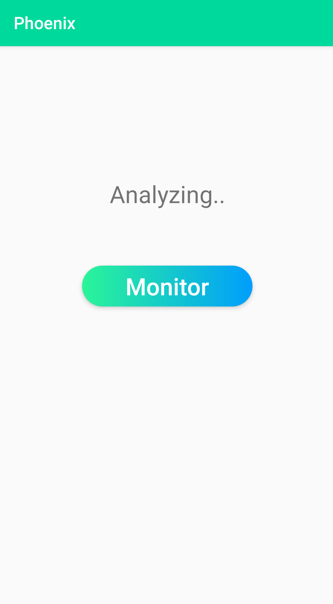
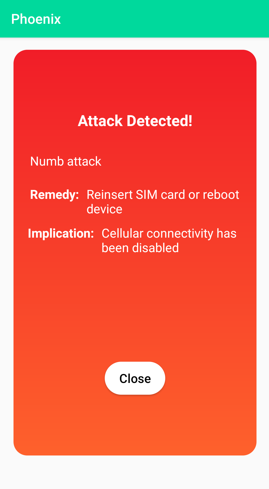
Appendix C Evaluation
In this section we provide more in depth results for the experiments described in Section 8. Additionally, we provide a figure for the DFA signature to detect the AKA Bypass Attack [38].
.
C.1 Training Time and Size of Synthesized Signatures
In this subsection we present the training time and size of all the synthesized signatures.
Table 9 provides the training time in seconds and the corresponding size for all the synthesized Mealy Machine signatures.
Table 10 provides the training time in seconds and the corresponding size for all the synthesized PLTL and DFA signatures. Note that the PLTL synthesizer produces different signatures for each attack. An exception to this is the Measurement Report which we had to invoke with traces due to it timing out. When the synthesizer was invoked with traces it was not capable of synthesizing signatures, however, it was able to synthesize one.
| Size | States | Transitions | Input | Output | Training Time |
| NAS | |||||
| 50 | 2 | 60 | 32 | 11 | 0.1 |
| 100 | 2 | 59 | 32 | 11 | 0.07 |
| 250 | 2 | 55 | 32 | 11 | 0.08 |
| 500 | 5 | 118 | 32 | 11 | 0.1 |
| 1250 | 4 | 113 | 32 | 11 | 0.16 |
| 2500 | 4 | 108 | 32 | 11 | 0.21 |
| RRC | |||||
| 50 | 25 | 435 | 33 | 6 | 0.06 |
| 100 | 30 | 466 | 33 | 6 | 0.03 |
| 250 | 23 | 409 | 33 | 6 | 0.04 |
| 500 | 28 | 525 | 33 | 6 | 0.05 |
| 1250 | 46 | 955 | 33 | 6 | 0.06 |
| 2500 | 2 | 65 | 33 | 6 | 0.08 |
| Attack name | Dataset Size |
|
|
|
|
|
|
|
||||||||||||||
| NAS | ||||||||||||||||||||||
| Attach Reject | 50 | 0.05 | 21.44 | 7 | 80 | 17 | 1 | 1 | ||||||||||||||
| 100 | 0.67 | 49.7 | 2 | 33 | 17 | 1 | 1 | |||||||||||||||
| 250 | 0.67 | 137.25 | 18 | 140 | 17 | 1 | 1 | |||||||||||||||
| 500 | 0.67 | 389.94 | 22 | 286 | 19 | 1 | 1 | |||||||||||||||
| 1250 | 1 | TIMEOUT | 4 | 60 | 18 | N/A | N/A | |||||||||||||||
| 2500 | 0.5 | TIMEOUT | 2 | 35 | 18 | N/A | N/A | |||||||||||||||
| Authentication Failure | 50 | 0.29 | 14.07 | 3 | 36 | 17 | 1 | 1 | ||||||||||||||
| 100 | 0.6 | 43.77 | 5 | 64 | 17 | 1 | 1 | |||||||||||||||
| 250 | 0.43 | 114.26 | 9 | 101 | 17 | 1 | 1 | |||||||||||||||
| 500 | 0.375 | 379.76 | 17 | 184 | 18 | 1 | 1 | |||||||||||||||
| 1250 | 0.5 | 1677.92 | 5 | 62 | 18 | 1 | 1 | |||||||||||||||
| 2500 | 0.38 | TIMEOUT | 4 | 58 | 18 | N/A | N/A | |||||||||||||||
| EMM Information | 50 | 0.17 | 26.62 | 10 | 104 | 18 | 1 | 1 | ||||||||||||||
| 100 | 0.5 | 50.25 | 4 | 53 | 18 | 1 | 1 | |||||||||||||||
| 250 | 0.2 | 463.9 | 3 | 47 | 18 | 1 | 1 | |||||||||||||||
| 500 | 0.375 | 1372.09 | 11 | 120 | 18 | 1 | 1 | |||||||||||||||
| 1250 | 0.375 | TIMEOUT | 2 | 35 | 19 | N/A | N/A | |||||||||||||||
| 2500 | 0.6 | TIMEOUT | 5 | 64 | 18 | N/A | N/A | |||||||||||||||
| IMEI Catching | 50 | 0.5 | 22.42 | 12 | 106 | 20 | 1 | 1 | ||||||||||||||
| 100 | 0.3 | 46.78 | 5 | 81 | 19 | 1 | 1 | |||||||||||||||
| 250 | 0.33 | 142.52 | 4 | 69 | 19 | 1 | 1 | |||||||||||||||
| 500 | 0.3 | 370.02 | 4 | 65 | 20 | 1 | 1 | |||||||||||||||
| 1250 | 0.8 | TIMEOUT | 6 | 99 | 19 | N/A | N/A | |||||||||||||||
| 2500 | 0.3 | TIMEOUT | 3 | 46 | 19 | N/A | N/A | |||||||||||||||
| IMSI Catching | 50 | 0.15 | 26.61 | 5 | 64 | 20 | 1 | 1 | ||||||||||||||
| 100 | 0.27 | 58.55 | 5 | 80 | 19 | 1 | 1 | |||||||||||||||
| 250 | 0.25 | 149.23 | 14 | 166 | 20 | 1 | 1 | |||||||||||||||
| 500 | 0.5 | 329.04 | 7 | 107 | 20 | 1 | 1 | |||||||||||||||
| 1250 | 0.6 | TIMEOUT | 3 | 49 | 20 | N/A | N/A | |||||||||||||||
| 2500 | 0.38 | TIMEOUT | 2 | 36 | 19 | N/A | N/A | |||||||||||||||
| Malformed Identity Request | 50 | 0.33 | 21.94 | 8 | 101 | 20 | 1 | 1 | ||||||||||||||
| 100 | 0.23 | 51.89 | 18 | 191 | 20 | 1 | 1 | |||||||||||||||
| 250 | 0.5 | 190.94 | 12 | 146 | 21 | 1 | 1 | |||||||||||||||
| 500 | 0.23 | 370.37 | 9 | 116 | 21 | 1 | 1 | |||||||||||||||
| 1250 | 0.33 | TIMEOUT | 4 | 69 | 21 | N/A | N/A | |||||||||||||||
| 2500 | 0.43 | TIMEOUT | 4 | 66 | 20 | N/A | N/A | |||||||||||||||
| Null Encryption | 50 | 0.38 | 18.29 | 4 | 53 | 20 | 1 | 1 | ||||||||||||||
| 100 | 0.6 | 47.22 | 4 | 54 | 20 | 1 | 1 | |||||||||||||||
| 250 | 0.6 | 161.44 | 12 | 158 | 21 | 1 | 1 | |||||||||||||||
| 500 | 0.3 | 385.91 | 13 | 150 | 21 | 1 | 1 | |||||||||||||||
| 1250 | 0.43 | TIMEOUT | 10 | 119 | 21 | N/A | N/A | |||||||||||||||
| 2500 | 0.5 | TIMEOUT | 5 | 87 | 21 | N/A | N/A | |||||||||||||||
| Numb Attack | 50 | 0.43 | 57.05 | 4 | 44 | 18 | 2 | 2 | ||||||||||||||
| 100 | 0.2 | 144.87 | 4 | 39 | 18 | 2 | 2 | |||||||||||||||
| 250 | 0.2 | 359.68 | 3 | 31 | 19 | 2 | 2 | |||||||||||||||
| 500 | 0.27 | 558.54 | 3 | 35 | 19 | 2 | 2 | |||||||||||||||
| 1250 | 0.17 | TIMEOUT | 6 | 75 | 20 | N/A | N/A | |||||||||||||||
| 2500 | 0.23 | TIMEOUT | 3 | 33 | 20 | N/A | N/A | |||||||||||||||
| Service Reject | 50 | 0.21 | 33.93 | 7 | 100 | 18 | 1 | 1 | ||||||||||||||
| 100 | 0.33 | 82.2 | 2 | 34 | 18 | 1 | 1 | |||||||||||||||
| 250 | 0.23 | 153.34 | 5 | 71 | 18 | 1 | 1 | |||||||||||||||
| 500 | 0.33 | 1110.77 | 25 | 279 | 18 | 1 | 1 | |||||||||||||||
| 1250 | 0.67 | TIMEOUT | 2 | 35 | 18 | N/A | N/A | |||||||||||||||
| 2500 | 0.6 | TIMEOUT | 2 | 35 | 18 | N/A | N/A | |||||||||||||||
| TAU Reject | 50 | 0.43 | 21.97 | 2 | 35 | 19 | 1 | 1 | ||||||||||||||
| 100 | 0.43 | 55.51 | 9 | 118 | 19 | 1 | 1 | |||||||||||||||
| 250 | 0.375 | 156.81 | 2 | 37 | 19 | 1 | 1 | |||||||||||||||
| 500 | 0.43 | 348.59 | 2 | 36 | 19 | 1 | 1 | |||||||||||||||
| 1250 | 0.33 | TIMEOUT | 15 | 187 | 19 | N/A | N/A | |||||||||||||||
| 2500 | 0.3 | TIMEOUT | 6 | 66 | 19 | N/A | N/A | |||||||||||||||
| RRC | ||||||||||||||||||||||
| AKA Bypass | 50 | 0.3 | 2782.81 | 10 | 98 | 19 | 3 | 3 | ||||||||||||||
| 100 | 0.2 | TIMEOUT | 15 | 166 | 22 | N/A | N/A | |||||||||||||||
| 250 | 0.8 | TIMEOUT | 38 | 519 | 22 | N/A | N/A | |||||||||||||||
| 500 | 0.3 | TIMEOUT | 28 | 323 | 22 | N/A | N/A | |||||||||||||||
| 1250 | 0.33 | TIMEOUT | 76 | 886 | 22 | N/A | N/A | |||||||||||||||
| 2500 | 0.6 | TIMEOUT | 118 | 1447 | 22 | N/A | N/A | |||||||||||||||
| IMSI Cracking (4G) | 50 | 0.56 | 216.51 | 5 | 92 | 23 | 2 | 2 | ||||||||||||||
| 100 | 0.33 | 661.59 | 17 | 245 | 28 | 2 | 2 | |||||||||||||||
| 250 | 1 | 1428.2 | 4 | 82 | 24 | 2 | 2 | |||||||||||||||
| 500 | 0.67 | TIMEOUT | 3 | 80 | 32 | N/A | N/A | |||||||||||||||
| 1250 | 0.33 | TIMEOUT | 7 | 156 | 33 | N/A | N/A | |||||||||||||||
| 2500 | 0.67 | TIMEOUT | 4 | 100 | 33 | N/A | N/A | |||||||||||||||
| Measurement Report | 20 | 0.71 | TIMEOUT* | 14 | 202 | 23 | 3 | 3 | ||||||||||||||
| 50 | 0.38 | TIMEOUT | 13 | 182 | 21 | N/A | N/A | |||||||||||||||
| 100 | 0.3 | TIMEOUT | 6 | 89 | 23 | N/A | N/A | |||||||||||||||
| 250 | 0.33 | TIMEOUT | 43 | 537 | 27 | N/A | N/A | |||||||||||||||
| 500 | 0.25 | TIMEOUT | 53 | 712 | 27 | N/A | N/A | |||||||||||||||
| 1250 | 0.33 | TIMEOUT | 122 | 1646 | 27 | N/A | N/A | |||||||||||||||
| 2500 | 0.22 | TIMEOUT | 161 | 2184 | 27 | N/A | N/A | |||||||||||||||
| Paging with IMSI | 50 | 0.25 | 57.31 | 8 | 135 | 23 | 1 | 1 | ||||||||||||||
| 100 | 0.25 | 51.66 | 3 | 65 | 24 | 1 | 1 | |||||||||||||||
| 250 | 0.15 | 146.74 | 29 | 487 | 24 | 1 | 1 | |||||||||||||||
| 500 | 0.12 | 517.27 | 2 | 46 | 24 | 1 | 1 | |||||||||||||||
| 1250 | 0.25 | TIMEOUT | 3 | 73 | 27 | N/A | N/A | |||||||||||||||
| 2500 | 0.18 | TIMEOUT | 111 | 1835 | 27 | N/A | N/A | |||||||||||||||
| RLF Report | 50 | 0.25 | 1538.16 | 15 | 188 | 22 | 4 | 3 | ||||||||||||||
| 100 | 0.18 | TIMEOUT | 19 | 229 | 22 | N/A | N/A | |||||||||||||||
| 250 | 0.38 | TIMEOUT | 31 | 429 | 22 | N/A | N/A | |||||||||||||||
| 500 | 0.25 | TIMEOUT | 50 | 744 | 22 | N/A | N/A | |||||||||||||||
| 1250 | 0.14 | TIMEOUT | 97 | 1416 | 22 | N/A | N/A | |||||||||||||||
| 2500 | 0.08 | TIMEOUT | 117 | 1633 | 22 | N/A | N/A | |||||||||||||||
C.2 Evaluation Scores For All Synthesized Monitors
Table 11 provides the precision, recall, and F1 score for all the generated signatures. Note that since Mealy Machine builds a signature for all attacks, the Measurement Report attack was not evaluated when trained on traces since this was only a requirement for PLTL for that specific attack.
| Attack Experiment | Size | DFA Precision | DFA Recall | DFA F1 | PLTL Precision | PLTL Recall | PLTL F1 | MM Precision | MM Recall | MM F1 |
| NAS | ||||||||||
| Attach Reject | 50 | 0.35 | 0.799 | 0.487 | 1 | 1 | 1 | 1 | 0.979 | 0.989 |
| 100 | 1 | 1 | 1 | 1 | 1 | 1 | 1 | 1 | 1 | |
| 250 | 0.874 | 0.931 | 0.902 | 1 | 1 | 1 | 1 | 0.988 | 0.994 | |
| 500 | 0.855 | 0.808 | 0.831 | N/A | N/A | N/A | 1 | 1 | 1 | |
| 1250 | 0.697 | 0.674 | 0.685 | N/A | N/A | N/A | 1 | 1 | 1 | |
| 2500 | 1 | 1 | 1 | N/A | N/A | N/A | 1 | 0.767 | 0.868 | |
| Authentication Failure | 50 | 0.983 | 0.77 | 0.864 | 1 | 1 | 1 | 1 | 1 | 1 |
| 100 | 0.943 | 0.891 | 0.916 | 1 | 1 | 1 | 1 | 0.996 | 0.998 | |
| 250 | 0.751 | 0.962 | 0.844 | 1 | 1 | 1 | 1 | 1 | 1 | |
| 500 | 0.72 | 0.824 | 0.768 | N/A | N/A | N/A | 1 | 1 | 1 | |
| 1250 | 0.671 | 0.997 | 0.802 | N/A | N/A | N/A | 1 | 1 | 1 | |
| 2500 | 0.914 | 1 | 0.955 | N/A | N/A | N/A | 1 | 1 | 1 | |
| EMM Information | 50 | 0.242 | 0.949 | 0.386 | 1 | 1 | 1 | 1 | 1 | 1 |
| 100 | 0.624 | 0.85 | 0.72 | 1 | 1 | 1 | 1 | 1 | 1 | |
| 250 | 0.278 | 1 | 0.435 | 1 | 1 | 1 | 1 | 1 | 1 | |
| 500 | 0.353 | 0.989 | 0.52 | N/A | N/A | N/A | 1 | 1 | 1 | |
| 1250 | 1 | 1 | 1 | N/A | N/A | N/A | 1 | 1 | 1 | |
| 2500 | 0.81 | 0.998 | 0.894 | N/A | N/A | N/A | 1 | 1 | 1 | |
| IMEI Catching | 50 | 0.821 | 0.688 | 0.749 | 1 | 1 | 1 | 1 | 1 | 1 |
| 100 | 0.965 | 0.659 | 0.783 | 1 | 1 | 1 | 1 | 1 | 1 | |
| 250 | 0.999 | 0.972 | 0.985 | 1 | 1 | 1 | 1 | 1 | 1 | |
| 500 | 0.999 | 0.972 | 0.985 | N/A | N/A | N/A | 1 | 1 | 1 | |
| 1250 | 0.632 | 0.635 | 0.633 | N/A | N/A | N/A | 1 | 1 | 1 | |
| 2500 | 0.5 | 0.7 | 0.583 | N/A | N/A | N/A | 1 | 1 | 1 | |
| IMSI Catching | 50 | 0.538 | 0.876 | 0.667 | 1 | 1 | 1 | 1 | 1 | 1 |
| 100 | 0.653 | 0.985 | 0.785 | 1 | 1 | 1 | 1 | 1 | 1 | |
| 250 | 0.942 | 0.943 | 0.942 | 1 | 1 | 1 | 1 | 1 | 1 | |
| 500 | 0.981 | 0.966 | 0.973 | N/A | N/A | N/A | 1 | 0.999 | 0.999 | |
| 1250 | 0.977 | 1 | 0.988 | N/A | N/A | N/A | 1 | 1 | 1 | |
| 2500 | 1 | 1 | 1 | N/A | N/A | N/A | 1 | 0.997 | 0.998 | |
| Malformed Identity Request | 50 | 0.739 | 0.502 | 0.598 | 1 | 1 | 1 | 1 | 1 | 1 |
| 100 | 0.805 | 0.504 | 0.62 | 1 | 1 | 1 | 1 | 1 | 1 | |
| 250 | 0.746 | 0.702 | 0.723 | 1 | 1 | 1 | 1 | 1 | 1 | |
| 500 | 0.97 | 0.662 | 0.787 | N/A | N/A | N/A | 1 | 1 | 1 | |
| 1250 | 0.978 | 0.5 | 0.662 | N/A | N/A | N/A | 1 | 1 | 1 | |
| 2500 | 0.417 | 0.466 | 0.44 | N/A | N/A | N/A | 1 | 1 | 1 | |
| Null Encryption | 50 | 0.524 | 0.868 | 0.653 | 1 | 1 | 1 | 1 | 1 | 1 |
| 100 | 0.437 | 0.944 | 0.597 | 1 | 1 | 1 | 1 | 0.967 | 0.983 | |
| 250 | 0.822 | 0.965 | 0.888 | 1 | 1 | 1 | 1 | 1 | 1 | |
| 500 | 0.528 | 0.967 | 0.683 | N/A | N/A | N/A | 1 | 1 | 1 | |
| 1250 | 0.467 | 0.89 | 0.613 | N/A | N/A | N/A | 1 | 1 | 1 | |
| 2500 | 0.709 | 0.989 | 0.826 | N/A | N/A | N/A | 1 | 1 | 1 | |
| Numb Attack | 50 | 0.817 | 1 | 0.899 | 1 | 1 | 1 | 0.997 | 1 | 0.999 |
| 100 | 0.98 | 1 | 0.99 | 1 | 1 | 1 | 0.968 | 0.981 | 0.975 | |
| 250 | 1 | 1 | 1 | 1 | 1 | 1 | 1 | 1 | 1 | |
| 500 | 1 | 1 | 1 | 1 | 1 | 1 | 0.98 | 0.987 | 0.984 | |
| 1250 | 0.989 | 1 | 0.994 | N/A | N/A | N/A | 1 | 1 | 1 | |
| 2500 | 1 | 1 | 1 | N/A | N/A | N/A | 1 | 1 | 1 | |
| Service Reject | 50 | 0.704 | 0.721 | 0.712 | N/A | N/A | N/A | 1 | 0.944 | 0.971 |
| 100 | 1 | 1 | 1 | 1 | 1 | 1 | 1 | 1 | 1 | |
| 250 | 0.976 | 0.84 | 0.903 | 1 | 1 | 1 | 1 | 1 | 1 | |
| 500 | 0.765 | 0.857 | 0.808 | N/A | N/A | N/A | 1 | 0.975 | 0.987 | |
| 1250 | 1 | 1 | 1 | N/A | N/A | N/A | 1 | 1 | 1 | |
| 2500 | 1 | 1 | 1 | N/A | N/A | N/A | 1 | 0.902 | 0.948 | |
| TAU Reject | 50 | 1 | 0.877 | 0.934 | 1 | 1 | 1 | 1 | 1 | 1 |
| 100 | 0.627 | 0.951 | 0.756 | 1 | 1 | 1 | 1 | 1 | 1 | |
| 250 | 1 | 0.902 | 0.948 | 1 | 1 | 1 | 1 | 1 | 1 | |
| 500 | 1 | 1 | 1 | N/A | N/A | N/A | 1 | 1 | 1 | |
| 1250 | 0.98 | 0.67 | 0.796 | N/A | N/A | N/A | 1 | 1 | 1 | |
| 2500 | 1 | 0.902 | 0.948 | N/A | N/A | N/A | 1 | 1 | 1 | |
| RRC | ||||||||||
| AKA Bypass | 50 | 0.984 | 0.809 | 0.888 | 1 | 1 | 1 | 0.899 | 0.93 | 0.914 |
| 100 | 0.781 | 0.824 | 0.802 | N/A | N/A | N/A | 0.965 | 0.975 | 0.97 | |
| 250 | 0.817 | 0.812 | 0.814 | N/A | N/A | N/A | 0.989 | 0.996 | 0.993 | |
| 500 | 1 | 0.977 | 0.988 | N/A | N/A | N/A | 0.995 | 0.997 | 0.996 | |
| 1250 | 1 | 0.908 | 0.952 | N/A | N/A | N/A | 0.993 | 0.988 | 0.99 | |
| 2500 | 1 | 0.95 | 0.974 | N/A | N/A | N/A | 1 | 1 | 1 | |
| IMSI Cracking | 50 | 1 | 1 | 1 | 1 | 1 | 1 | 0.92 | 0.994 | 0.956 |
| 100 | 1 | 1 | 1 | 1 | 1 | 1 | 0.736 | 1 | 0.848 | |
| 250 | 1 | 0.5 | 0.667 | 1 | 1 | 1 | 0.682 | 1 | 0.811 | |
| 500 | 1 | 1 | 1 | N/A | N/A | N/A | 0.66 | 0.998 | 0.795 | |
| 1250 | 1 | 1 | 1 | N/A | N/A | N/A | 0.708 | 1 | 0.829 | |
| 2500 | 1 | 1 | 1 | N/A | N/A | N/A | 0.671 | 1 | 0.803 | |
| Measurement Report | 20 | 0.434 | 0.456 | 0.445 | 1 | 1 | 1 | N/A | N/A | N/A |
| 50 | 0.687 | 0.565 | 0.62 | N/A | N/A | N/A | 0.878 | 0.864 | 0.871 | |
| 100 | 0.998 | 1 | 0.792 | N/A | N/A | N/A | 0.948 | 0.937 | 0.943 | |
| 250 | 0.87 | 0.689 | 0.769 | N/A | N/A | N/A | 0.984 | 0.964 | 0.974 | |
| 500 | 0.84 | 0.759 | 0.887 | N/A | N/A | N/A | 0.989 | 0.985 | 0.987 | |
| 1250 | 0.854 | 0.739 | 0.445 | N/A | N/A | N/A | 0.993 | 0.976 | 0.984 | |
| 2500 | 0.948 | 0.834 | 0.62 | N/A | N/A | N/A | 1 | 1 | 1 | |
| RLF Report | 50 | 0.826 | 0.632 | 0.716 | 1 | 1 | 1 | 0.932 | 0.816 | 0.87 |
| 100 | 0.268 | 0.519 | 0.353 | N/A | N/A | N/A | 0.94 | 0.896 | 0.918 | |
| 250 | 0.515 | 0.518 | 0.516 | N/A | N/A | N/A | 0.989 | 0.957 | 0.973 | |
| 500 | 0.55 | 0.545 | 0.547 | N/A | N/A | N/A | 0.996 | 0.956 | 0.976 | |
| 1250 | 0.511 | 0.515 | 0.513 | N/A | N/A | N/A | 0.995 | 0.966 | 0.98 | |
| 2500 | 0.829 | 0.639 | 0.722 | N/A | N/A | N/A | 1 | 1 | 1 | |
| Paging with IMSI | 50 | 50 | 0.634 | 0.918 | 1 | 1 | 1 | 1 | 0.998 | 0.999 |
| 100 | 100 | 0.653 | 1 | 1 | 1 | 1 | 1 | 1 | 1 | |
| 250 | 250 | 0.591 | 0.963 | 1 | 1 | 1 | 1 | 1 | 1 | |
| 500 | 500 | 0.653 | 1 | 1 | 1 | 1 | 1 | 0.998 | 0.999 | |
| 1250 | 1250 | 0.653 | 1 | N/A | N/A | N/A | 1 | 1 | 1 | |
| 2500 | 2500 | 0.632 | 0.571 | N/A | N/A | N/A | 1 | 1 | 1 | |
C.3 Multithreading Evaluation
Threading.
Mealy Machine outperforms both DFA and PLTL when it comes to monitoring all attack signatures at once. The reason behind this is that Mealy Machine use a unified signature for all attacks and thus requires only one internal state, while DFA and PLTL require states for attack signatures. To accelerate the DFA- and PLTL-based monitoring, an intuitive approach is to employ multithreading. We, therefore, investigate whether threading improves the efficiency for these monitors. For this, we instantiate three different versions of DFA and PLTL monitors. The first instantiation is called “No Threading” which sequentially invokes each monitor per layer and then analyzes the results. The second implementation is called “N/2 Threading“ and it relies on threads, where each thread runs two monitors and then communicates the results to the main thread. The third implementation is called “N Threading“, where threads are spawned, one per attack. Similar to the N/2 Threading, these spawned threads converse back the results from each individual monitor to the main thread.
Table 12 shows the average number of messages processed per second by different monitoring approaches when different levels of multithreading are employed. We observe that threading does not improve the performance and in fact, there is a clear relation between performance degradation and number of threads. For instance, NAS with no threading was able to parse over messages per second while threads dropped this to messages per second. This result can be attributed to the fact that Python prohibits two threads from executing simultaneously [8].
| Monitor | Threading | Avg. | SD. |
| RRC | |||
| DFA | N Threading | 1.8 | 3.3 |
| N/2 Threading | 12.5 | 9.7 | |
| No Threading | 51730.6 | 158596.4 | |
| PLTL | N Threading | 2.25 | 4.6 |
| N/2 Threading | 13.7 | 10.19 | |
| No Threading | 7286.3 | 55599 | |
| NAS | |||
| DFA | N Threading | 1.2 | 3.6 |
| N/2 Threading | 4.7 | 5.8 | |
| No Threading | 34164 | 224904.7 | |
| PLTL | N Threading | 1.23 | 3.73 |
| N/2 Threading | 4.7 | 6.2 | |
| No Threading | 3771 | 62512.74 | |
C.4 Lower Bound Memory Requirement Formulas and Results
For a monitor to be viable, the static and dynamic memory overhead are required to be small. However, precisely measuring the memory requirement is unreliable and hence we resort to providing lower bound memory requirements for each of the monitoring state. For measuring lower bound, we resort the minimum number of bits one would require to represent the internal monitoring state. This also serves as an indicator of possible update size in bits when a new attack is discovered. For this evaluation, we consider the signatures generated by each monitor with the most data they can handle.
DFA.
For DFA, the internal data structure consists of states, transitions, and an alphabet. If a monitor consists of states, transitions, and an alphabet of size , then the following functions represent the minimum number of bits required to represent a DFA. For representing each transition, the number of bits required are since the monitor must keep in memory the starting start, ending state, and the letter in that alphabet which will triggers the transition. For each state, the number of bits required are 2; one bit indicating whether the state is a start state and another indicating whether it is an accepting state. Also, during the monitoring process the monitor must keep in memory the current state, requiring bits. Therefore, DFA requires bits of memory. In addition, we need 12 bytes to account for the number of states (), number of transitions (), and the size of the alphabet .
Mealy Machine.
Mealy Machine’s internal structure consists of states and transitions, similar to that of DFA except that transitions are associated with an output letter and the states are no longer are rejecting or accepting. If a monitor consists of states, transitions, the size of the input alphabet is , and the output alphabet size is then the following functions represent the lower bound of Mealy Machine’s memory consumption. For each transition, the number of bits required are . Similar to DFA, for each transition we must keep in memory the starting state, ending state, and the letter in the input alphabet that will trigger this transition. In addition, it must also keep in memory the output letter it generates when the transition is taken. For each state the number of bits required is 1 since it must keep track whether the state is a starting state. Like DFA, Mealy Machine must also keep track of the current state while running, requiring bits. In total, Mealy Machine requires a total of bits of memory. To represent this structure in a signature file, we add 16 bytes to accounts for the number of states (), the number of transitions (), the size of input alphabet (), and the size of output alphabet ().
PLTL.
To represent the size of the internal structure of a PLTL based monitor, we rely on counting the number of propositions and operators in the formula. If a formula has propositions, operators, is the size of the alphabet and is the total number of distinct operators supported. Note that is fixed at 9 as defined in Section 1. The internal structure then requires bits.
We also need 8 bytes to account for the number of propositions (), and the number of operators . In addition, we need bits for capturing the truth value of each subformula of a signature (1 bit for the previous truth value and 1 bit for the current truth value).
| Mealy Machine | ||||
| Layer | States | Transition | Input | Output |
| NAS | 4 | 108 | 32 | 11 |
| RRC | 2 | 65 | 33 | 6 |
| PLTL | ||||
| Layer | PLTL Propositions | PLTL Operators | Alphabet | |
| NAS | 11 | 11 | 32 | |
| RRC | 13 | 12 | 33 | |
| DFA | ||||
| Layer | States | Transitions | Alphabet | |
| NAS | 36 | 526 | 32 | |
| RRC | 511 | 7199 | 33 | |
Lower-bound Memory Requirements.
We present the number of states, the number of transitions, the alphabet size, and the formula size required for lower bound memory calculation, when considering all 15 attacks, in Table 13 and the corresponding minimum bits required in Table 14. Note that, we acknowledge that this lower bound does not account of additional bytes needed for parsing signatures and attack remedies.
As expected, PLTL proves to be highly memory efficient. In addition to this, DFA proves to require a significantly higher number of bits than Mealy Machine because DFA keeps a state machine per attack. The discrepancy between NAS and RRC for DFA is due to the fact that the DFAs for NAS have 36 different states in total, while the RRC DFAs have a total of 511 states.
| Layer | PLTL | Mealy Machine | DFA |
| NAS | 90 | 1186 | 8146 |
| RRC | 104 | 629 | 166886 |
| Total | 194 | 1815 | 175033 |