Direct Quantum Communications in the Presence of Realistic Noisy Entanglement
Abstract
To realize the Quantum Internet, quantum communications require pre-shared entanglement among quantum nodes. However, both the generation and the distribution of the maximally-entangled quantum states are inherently contaminated by quantum decoherence. Conventionally, the quantum decoherence is mitigated by performing the consecutive steps of quantum entanglement distillation followed by quantum teleportation. However, this conventional approach imposes a long delay. To circumvent this impediment, we propose a novel quantum communication scheme relying on realistic noisy pre-shared entanglement, which eliminates the sequential steps imposing delay in the standard approach. More precisely, our proposed scheme can be viewed as a direct quantum communication scheme capable of improving the quantum bit error ratio (QBER) of the logical qubits despite relying on realistic noisy pre-shared entanglement. Our performance analysis shows that the proposed scheme offers competitive QBER, yield, and goodput compared to the existing state-of-the-art quantum communication schemes, despite requiring fewer quantum gates.
Index Terms:
Quantum communication, quantum entanglement, quantum error-correction, quantum stabilizer codes, Quantum InternetI Introduction
Enabling quantum communications among quantum devices within the Quantum Internet [1, 2, 3] will ultimately lead to various groundbreaking applications. These radically new applications do not necessarily have classical counterparts [4] and they are not limited to the already well-known secure classical communications, blind computation, distributed quantum computing, and quantum secret sharing [5, 2, 6, 7, 8]. Naturally, the reliable transfer of quantum information is sought across the quantum network relying on quantum channels [9, 10]. However, the quantum channels inevitably impose deleterious quantum decoherence, which inflicts quantum errors [11, 12]. In the classical domain, the errors imposed by the communication channels can be mitigated using error-control codes [13]. The key idea of error-control codes is to attach appropriately designed redundancy to the information bits by an encoding process, which is utilized by the decoder to correct a certain number of errors. However, observing and/or copying quantum information is not allowed in the quantum domain due to the no-cloning theorem and the quantum measurement postulate. This motivates the carefully constructed design of quantum error-correction codes (QECCs) [14, 15, 16, 17].
QECCs constitute potent error mitigation techniques required for tackling the deleterious effect of quantum decoherence. Similar to the classical error-correction codes, QECCs rely on attaching redundant qubits to the logical qubits to provide additional information that can be exploited for quantum error-correction during the decoding step [18]. Interestingly, the whole encoding and decoding process can be completed without actually observing the physical qubits and thus, preserving the integrity of the quantum information conveyed by the physical qubits. In the quantum domain, the redundant qubits can be in form of auxiliary qubits initialized to the or states, or in the form of pre-shared maximally-entangled quantum states, which are normally assumed to be noise-free. For a two-qubit system, the maximally-entangled quantum states are represented by the Einstein-Podolsky-Rosen (EPR) pairs. The state-of-the-art studies typically assume that the EPR pairs are pre-shared among quantum devices within the quantum networks before any quantum communication protocol is initiated. Hence, the EPR pairs can be considered as the primary resource within the Quantum Internet [10].
Having pre-shared entanglement offers several beneficial features for QECCs. Firstly, it can be used for conveniently transforming some powerful classical error-correction codes that do not satisfy the symplectic criterion111A pair of classical error-correction codes having parity-check matrices and can be transformed to a quantum error-correction code if they satisfy . into their quantum counterparts [19, 20, 21]. Secondly, they can also be used for increasing the error-correction capability of quantum stabilizer codes (QSCs) [22]. Indeed, there are several types of QECCs in the literature that exploit pre-shared entanglement, such as entanglement-assisted QSCs [23], entanglement-aided canonical codes [24], as well as teleportation-based QECCs [25]. However, in all the above-mentioned schemes, the pre-shared entanglement is considered to be noise-free.
In a scenario having realistic noisy pre-shared entanglement, QECCs are invoked for quantum entanglement distillation (QED) [26, 27, 28, 29, 17], which is followed by quantum teleportation [30] for transferring the quantum information. QED can be viewed as a specific application of QECCs, where several copies of noisy pre-shared EPR pairs are discarded to obtain fewer but less noisy EPR pairs. In this approach, QED and quantum teleportation have to be performed subsequently, which typically imposes excessive practical delay. Additionally, state-of-the-art QED schemes will always have some residual quantum noise, unless infinitely many noisy pre-shared EPR pairs are discarded during QED. Unfortunately, this residual quantum noise is carried over to the logical qubits during the quantum teleportation process and hence it affects the integrity of the quantum information. In this treatise, we refer to this specific quantum communication scheme relying on the consecutive steps of QED and quantum teleportation as QED+QT.
Another QECC-aided technique operating in the presence of noisy pre-shared entanglement was introduced in [31], which we will refer to as quantum stabilizer codes using imperfect pre-shared entanglement (QSC-IE). Compared to the QED-based schemes which apply the QECCs locally on the pre-shared EPR pairs split between the transmitter and the receiver, the scheme presented in [31] requires that the pre-shared portion of the EPR pairs at the transmitter side has to be sent to the receiver in order to apply stabilizer measurements to both qubits of the EPR pairs. Consequently, a relatively high number of the two-qubit quantum gates – as exemplified by quantum controlled-NOT (CNOT) gate – are required for performing these measurements. Furthermore, by reasoning for a fixed number of pre-shared EPR pairs and logical qubits, the QSC-IE scheme demands for a higher number of quantum channel uses, to apply stabilizer measurements to both qubits of the EPR pairs.
Having said that, in this treatise, we propose a novel solution for achieving a reliable quantum communication, despite using noisy pre-shared entanglement. Firstly, we eliminate the idealized simplifying assumption of having noise-free pre-shared EPR pairs. Secondly, we devise a scheme for avoiding the undesired delay imposed by the consecutive steps of QED and quantum teleportation in conventional twin-step QED+QT schemes. By contrast, our proposed scheme can be viewed as a single-step direct quantum communication scheme, which exploits the quantum noise experienced by the pre-shared EPR pairs for improving the reliability of quantum communications by encoding the logical qubits directly with the aid of noisy pre-shared EPR pairs. As it will become more evident later in this treatise, our proposal may be deemed philosophically reminiscent of training-based equalization techniques in classical communications, which rely on pilot sequences for estimating the channel and then eliminating its impairments. Thirdly, we also eliminate the necessity of performing stabilizer measurements on both qubits of the pre-shared EPR pairs for the sake of reducing: (i) the number of quantum gates required to achieve reliable quantum communications and (ii) the uses of the considered quantum channel. Indeed, by relying solely on the local measurements of the pre-shared EPR pairs, our proposal significantly reduces the number of the required two-qubit quantum gates as well as the number of quantum channel uses by reasoning with the same number of pre-shared EPR pairs. Table I boldly and explicitly contrasts our proposed scheme to the existing schemes of amalgamating pre-shared entanglement and QECCs. Naturally, our proposal is also suitable for the scenario of noise-free pre-shared entanglement, similarly to the EA-QECC schemes. In Section VI, we formally show that our proposed scheme outperforms the state-of-the-art.
| Scheme | Noisy Pre-Shared Entanglement | Direct Communication | Stabilizer Measurement |
| QED+QT | Yes | No | Yes |
| QSC-IE | Yes | Yes | Yes |
| EA-QECC | No | Yes | Yes |
| Proposed | Yes | Yes | No |
Our novel contributions can be summarized as follows:
-
1.
We propose a new scheme for achieving reliable quantum communications despite relying on noisy pre-shared entanglement. More specifically,
-
2.
We carry out the performance analysis of the proposed scheme for both error-detection and error-correction based schemes over quantum depolarizing channels. The results show that the proposed scheme offers competitive performance in terms of its qubit error ratio, yield, and goodput despite requiring fewer quantum gates than the existing state-of-the-art schemes.
-
3.
In case of noise-free pre-shared entanglement, the proposed scheme outperforms even the existing entanglement-assisted quantum stabilizer codes.
The rest of the treatise is organized as follows. In Section II, we commence by presenting the quantum communication model. In Section III, we detail the explicit formulation of our proposed scheme for direct noiseless quantum communication over noisy pre-shared entanglement. In Section IV, we exemplify our scheme proposed for error-detection, while in Section V, we conceive its counterpart for error-correction. In Section VI, we show the suitability of our proposal for quantum computing applications. Finally, we conclude in Section VII by also discussing some future research directions.
II System Model
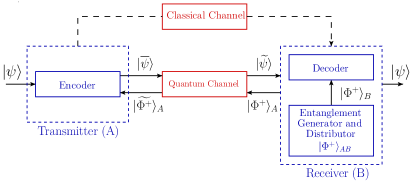
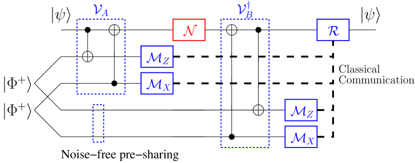
As discussed in [10], both entanglement generation and distribution are the key for the Quantum Internet. The specific “location” of the device implementing these functionalities – a.k.a. the entanglement generator and distributor – varies among the different schemes and solutions [10]. However, there is a general agreement in the literature that the employment of the so-called “at both end-points” scheme is vital for the Quantum Internet by enabling on-demand communication capabilities at the quantum nodes. According to the “at both end-points” scheme, the entanglement generator and distributor is embedded within both the transmitter and the receiver [10]. In this light, we consider the quantum communication model depicted in Fig. 1. The model includes a transmitter , a receiver , the entanglement generator and distributor, a noisy quantum channel and a classical channel. Without loss in generality, in the figure we only highlight the entanglement generator and distributor used at the receiver, since it is exploited by the proposed scheme. The quantum communication session commences with the generation of the EPR pairs, whose quantum state is
| (1) |
In the rest of this treatise, we assume that the pre-shared EPR pairs are initialized to the quantum state of , where the subscript indicates that the first qubit of each EPR pair is held by and the second qubit is held by . In Fig. 1, the entanglement generator is located at . Hence, the first qubit of the EPR pairs has to be sent by through the quantum channel, while the second qubit of the EPR pairs is available immediately at . After obtains the first qubit of the EPR pairs , it can be exploited for transmitting the quantum information embedded within the logical quantum qubit . In addition to the pre-shared EPR pairs, and are also connected via a classical communication channel, which is considered to be noise-free222This assumption is not restrictive since we focus our attention on the quantum noise only. In case of a realistic noisy classical channel, the well-known classical error-mitigation techniques can be implemented..
The main goal of the quantum communication model of Fig. 1 is to faithfully transfer the quantum state from to assisted by the pre-shared EPR pairs and also by classical communications. To achieve this goal, may exploit the noisy pre-shared EPR pairs for appropriately encoding the logical qubits into , which is sent to . In addition to the received encoded quantum state , also obtains the classical bits gleaned from the measurement of the EPR-pair members at . Finally, performs a decoding procedure to reconstruct the original quantum state of the logical qubits by utilizing the qubits of the EPR-pair members at .
In this treatise, we consider one of the most general quantum channel models, namely the quantum depolarizing channel , a type of quantum Pauli channel. For a single-qubit system, the quantum depolarizing channel is described by [11]
| (2) |
where are the Pauli matrices, denotes the density matrix of the input quantum state, and denotes the depolarizing probability of the quantum channel . The Kraus operators of are given by , , , [11].
III Quantum Communication with Noisy Pre-Shared Entanglement
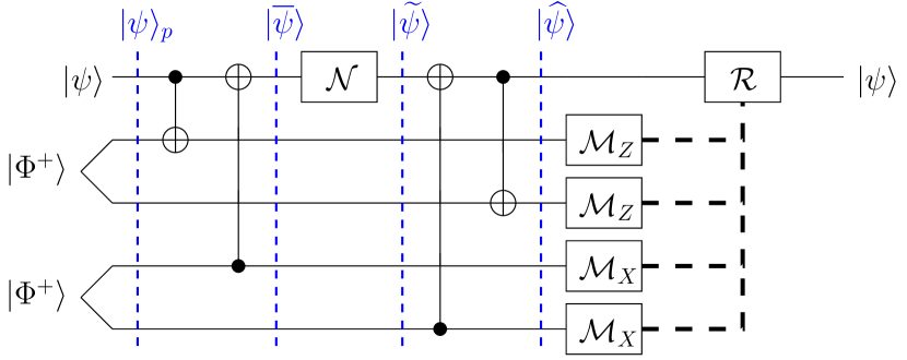
In this section, we present the general concept of our proposed scheme for performing both error-detection and error-correction. The schematic of the proposed scheme is depicted in Fig 2. Its operation commences by preparing the initialized quantum state as follows:
| (3) |
where represents the quantum state of logical qubits, while represents pairs of pre-shared EPR pairs between and . The subscripts and indicate that half of the EPR pairs are held by and the other half by .
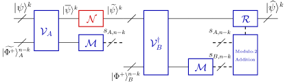
As we elucidated in Section II, the generation and the distribution of the EPR pairs to are contaminated by the quantum noise imposed by the quantum channels. Let us denote the -tuple Pauli operator inflicted by the quantum channel as . Then, we have
| (4) |
The quantum state of the logical qubits is encoded by a quantum encoder , where we exploit the noisy EPR-pair members at . The encoded state of the logical qubits is then sent through the quantum channel . Let us denote the -tuple Pauli operator inflicted by the quantum channel as . Then, we have
| (5) |
At the receiver side, the quantum decoder of Fig. 2 decodes the corrupted quantum state with the aid of the EPR-pair members at . To design the quantum encoder and the quantum decoder , we impose the reversible property333We note that in Fig. 2 there is a little notation-abuse, since we use the symbols and to denote the encoding and decoding performed on the qubits available at and , respectively. Instead, in (6), and denote the encoder and decoder acting on the global quantum state . However, this notation abuse can be tolerated since and in (6) leave the qubits unavailable at and , respectively, unchanged. on the initialized quantum state in (3), which is formulated as
| (6) |
Remark.
We note that in conventional QECCs, the reversible property of a noise-free scenario can always be guaranteed, since the quantum encoder and decoder act on the same physical qubits. By contrast, in our scheme, the quantum encoder only processes the logical qubits and the EPR-pair members at , whilst the quantum decoder only processes the logical qubits received via the noisy quantum channel and the EPR-pair members at .
By denoting the density matrix of as , it is possible to reformulate the proposed general scheme of Fig. 2 as the following supermap :
| (7) |
In (7), we take into account the effects of the quantum noise inflicted by the quantum channels utilized for both the distribution of the EPR-pair members at and for the transmission of the encoded state of the logical qubits. Furthermore, in (7), , represent the Kraus operators of the quantum channels444To be more precise and with a little notation-abuse, , denote the extended Kraus operators of the quantum channels, which account for the specific qubits affected by the quantum channels and for the increased dimension induced by the supermap of (7), acting on the global state ., while and are the matrix representations of the quantum encoder and decoder, respectively.
The scheme proposed in Fig. 2 is completed by local measurements on the EPR pairs whose outcomes control the operator depending the particular error-control strategy implemented. Specifically, to perform the associated error-control procedure, local measurements of the EPR pairs are performed for obtaining the classical bits555When EPR pairs are considered, the local measurements of the EPR pairs produce outcomes. To denote the associated vectors, we utilize the notation . and . Since no joint measurements are applied to the EPR pairs for the sake of reducing the number of quantum channels utilization, a syndrome-like quantity may be constructed from the modulo-2 addition of the classical measurement results as follows:
| (8) |
It is important to note that both and have chosen the appropriate pre-determined measurement basis for each of the EPR pairs.
In the case of the proposed error-detection schemes, the operator of Fig. 2 acts as a discard-and-retain unit based on the syndrome of (8). More specifically, if the syndrome values of (8) indicate the presence of errors, i.e. the syndrome values are not zeros , the operator will decide to discard the logical qubits , otherwise it will retain the logical qubits. By contrast, in the case of the proposed error-correction schemes, the operator represents an error-recovery procedure based on maximum-likelihood decoding relying on the syndrome values of (8). Specifically, the error-recovery procedure can be formally expressed as
| (9) |
where denotes the probability of experiencing the logical error imposed on the logical qubits , given that we obtain the syndrome values .
IV Error-Detection Scheme
In this section, we consider the error-detection of either a single logical qubit or of two logical qubits and carry out its performance analysis. We rely on Definition 10 and 11 for characterizing the performance of the proposed error-detection schemes.
Definition 1.
The success probability of the proposed error-detection schemes is defined as the conditional probability of obtaining the legitimate quantum state of the logical qubits, given that we obtain the all-zero syndrome values :
| (10) |
The relationship between the qubit error ratio (QBER) and the success probability can simply be defined as .
Definition 2.
The yield of the proposed error-detection schemes is defined as the ratio of logical qubits retained after the detection to the uses of the quantum channel :
| (11) |
Readers from the classical communication field may notice the relationship between the yield and goodput metrics. While yield has been widely used in the QED literature, goodput is a common metric utilized for normalizing the performance of classical coded communication systems with respect to the associated coding rate. The notion of goodput in the quantum domain is clarified in [32], where it is used for comparing the performance of various QECCs exhibiting different quantum coding rates and for determining their performance discrepancies with respect to the quantum capacity also known as the quantum hashing bound. We underline that yield and goodput are not the same metric, although they are intimately linked. More specifically, the goodput is defined as the product of the success probability of a given QECC by its quantum coding rate [32]. Therefore, the goodput of our proposed scheme may be reformulated as in Definition 12.
Definition 3.
The goodput of the proposed error-detection schemes is defined as the product of the success probability by the ratio of logical qubits to the uses of the quantum channel :
| (12) |
By comparing Definition 11 and Definition 12 we can observe the intrinsic relationship between the yield and the goodput.
IV-A Error-Detection for A Single Logical Qubit
Let us consider the proposed single qubit error-detection scheme depicted in Fig. 3, which utilizes only a single noisy EPR pair. More specifically, the encoding and decoding circuit of Fig. 2 is detailed in Fig. 3. We design the quantum encoder and decoder for ensuring that the reversible condition of (6) is satisfied. The quantum encoder and quantum decoder of Fig. 3 can be represented using unitary matrices as follows:
| (13) |
By scrutinizing (IV-A), it is readily seen that the reversible property is indeed satisfied, i.e. . Finally, the EPR pair is measured in the basis . The performance of the scheme proposed in Fig. 3 is characterized by Proposition 1.
Proposition 1.
The success probability of the error-detection scheme depicted in Fig. 3 over quantum depolarizing channels relying on a single noisy EPR pair is given by:
| (14) |
while the yield is given by:
| (15) |
Proof:
Please refer to Appendix A. ∎
First, we compare our proposed scheme to the state-of-the-art QED+QT schemes. Specifically, we compare the scheme proposed in Fig. 3 to the single-round recurrence QED of [27] and to the quantum stabilizer code (QSC)-based QED of [28, 29, 17] having the stabilizer operator of . We assume that the quantum teleportation step is noise-free and therefore the QBER of the benchmark schemes is directly determined by the QBER of the associated QED scheme. Note that both the benchmark schemes require two noisy pre-shared EPR pairs, while our proposed scheme only needs a single noisy pre-shared EPR pair.
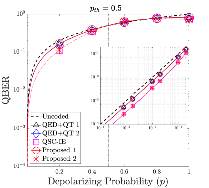
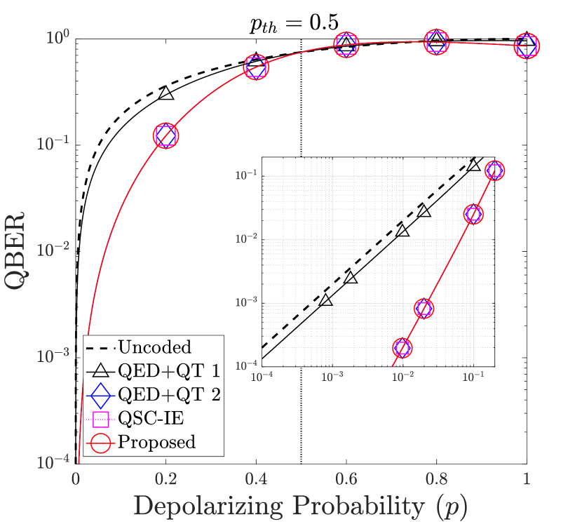
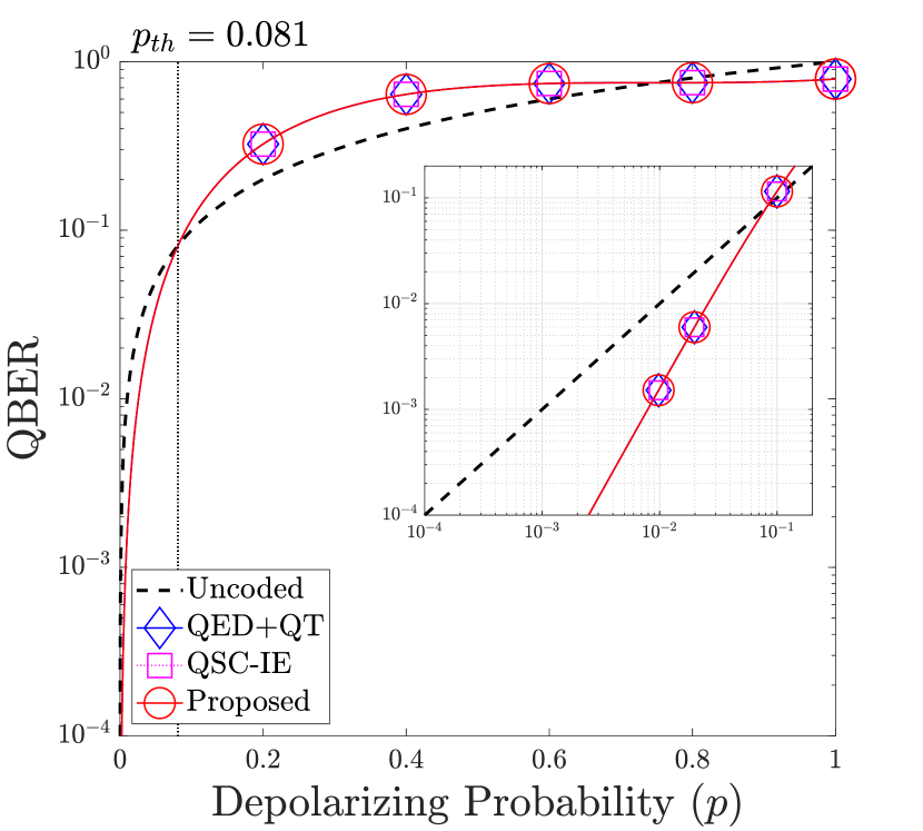
The QBER is portrayed in Fig. 4, where we label the performance of the scheme presented in Fig. 3 as ‘Proposed 1’, the recurrence-based scheme as ‘QED+QT 1’, and the QSC-based scheme as ‘QED+QT 2’. We observe that the QBER of the scheme presented in Fig. 3 matches that of QED+QT schemes, without requiring the additional quantum teleportation step, which also relies on the idealized assumption of being noise-free for both benchmarks. Furthermore, we observe that all the schemes considered are only capable of detecting a single error. Additionally, we mark the probability threshold using the vertical black dotted line in Fig. 4, highlighting the particular depolarizing probability value, below which the proposed error-detection scheme improves the QBER of the logical qubit. Specifically, in Fig. 4, we obtain the probability threshold of .
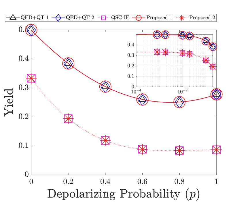
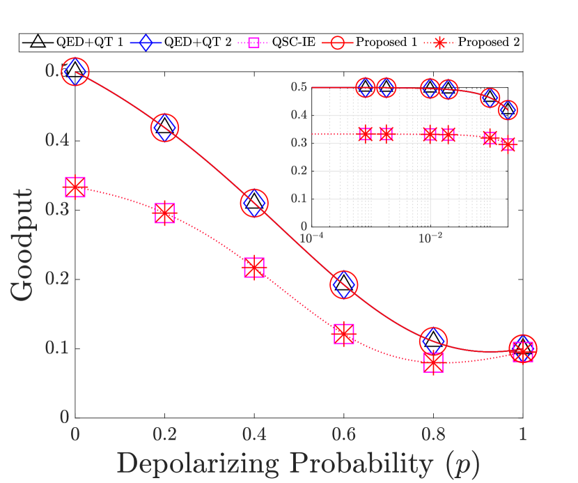
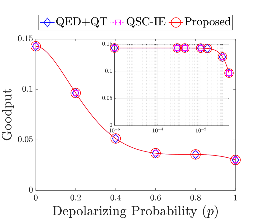
In Fig. 5(a), we report the performance of our proposed scheme in terms of its yield. We observe that our proposed scheme provides an identical yield to the benchmark schemes. However, two noisy pre-shared EPR pairs are used for obtaining a single less noisy pre-shared EPR pair for both the recurrence-based and the QSC-based QED+QT schemes. This means that during the process one of the noisy pre-shared EPR pairs is discarded. By contrast, our protocol only needs a single noisy pre-shared EPR pair for achieving the same QBER performance. Finally, the goodput of our proposed error-detection scheme is presented in Fig. 5(b), which confirms again the intrinsic relationship between the yield and the goodput. Specifically, our proposal that provides an identical yield, gives us also an identical goodput.
Apart from its benefit of utilizing fewer pre-shared EPR pairs, our proposed scheme also offers a pair of additional advantages:
-
•
It does not suffer from long communication delay, since it does not require the consecutive steps of performing QED followed by quantum teleportation.
-
•
It requires fewer controlled-NOT (CNOT) quantum gates. Quantitatively, the proposed scheme of Fig. 3 requires a total of only two CNOT gates. By contrast, the recurrence-based QED+QT scheme requires a total of three CNOT gates: two for a single-round recurrence QED and one for quantum teleportation. As for the QSC-based QED+QT scheme, we need a total of seven CNOT gates: four for the measurement of stabilizer operators, two for the quantum inverse encoder, and one for quantum teleportation.
Let us elaborate a little further concerning the delay imposed by each quantum communication scheme specified in the first bullet point. The quantum entanglement distillation has to be completed before the quantum teleportation can be conducted within the QED+QT scheme. Specifically, within the quantum entanglement distillation step itself, the transmission delay is imposed by the associated classical communications. Let us assume that each classical communication takes a duration of . Therefore, for a recurrence QED scheme having rounds of distillation, the total transmission delay is equal to , since for each round of distillation requires a backward- and a forward-oriented classical communication phase – both of which can be carried out simultaneously for example using wavelength division multiplexing. By contrast, the total transmission delay imposed by a QSC-based QED is simply equal to , since it only needs a forward-oriented classical communication. Once the QED step has been completed, quantum teleportation has to be performed for transferring the quantum information from the transmitter to the receiver. Since quantum teleportation also requires another forward-oriented classical information phase, an additional delay of is introduced by the QED+QT scheme. Therefore, we have a total of transmission delay for the QSC-based QED+QT scheme. In case of recurrence-based QED+QT scheme, we have a transmission delay of . By contrast, the total transmission delay is only equal to for both the QSC-IE and the proposed schemes. However, it is important to note that we underestimate the QSC-IE quantum information processing delay, since QSC-IE scheme utilizes the stabilizer measurements differently from the proposed scheme.
Arguably, the delay imposed by the transmission of classical information required by the QED+QT scheme can be avoided by performing QED in an asynchronous way, implying that the QED is activated before the transmitter and the receiver have agreed to initiate their quantum communication. Consequently, an asynchronous QED+QT scheme requires a long-expiry quantum memory to store the distilled EPR pairs. However, the assumption of having a long-expiry quantum memory at both the transmitter and the receiver is indeed a strong one at the current state-of-the-art [33]. In the absence of long-expiry quantum memory, an asynchronous QED+QT scheme can be employed by performing continuous QED until both the transmitter and the receiver finally decide to initiate their quantum communication. However, it is clear that continuously performing QED consumes a high number of noisy pre-shared EPR pairs during the waiting period. Therefore, in this treatise, we consider an on-demand quantum communication model, as we have described in Section II. This model eliminates the stringent requirement of long-expiry quantum memory as well as the continuous operation of QED, which is achieved by only initializing quantum communication once both the transmitter and the receiver are ready to engage.
Regarding the number of CNOT gates mentioned in the second bullet point, it has been shown in [34, 35], that the number of CNOT gates provides a reasonable estimate of the severity of quantum error proliferation effects, when the realistic quantum encoder and decoder are potentially error-infested. Specifically, in this case, the overall proliferation of quantum errors is heavily dependent on the number of two-qubit quantum gates – exemplified by the CNOT gates. However, to fully characterize the performance of quantum communication schemes under the realistic scenario of having both noisy pre-shared entanglement and imperfect quantum gates, computer simulations are required. Thus, we will carry out this full-scale analysis in our future work.
Remark.
By invoking the simple scheme presented in Fig 3, we can attain both an identical yield and a reduced delay, despite relying on a reduced number of CNOT gates compared to the benchmarks, which is achieved without degrading the QBER.
In order to further generalize our analysis, let us compare the aforementioned schemes by using the same number of noisy pre-shared EPR-pairs. More specifically, we assume having two noisy pre-shared EPR-pairs for all the QED+QT schemes considered. Specifically, we modify the scheme proposed in Fig. 3 as seen in Fig. 6, where the first EPR pair is measured in the basis , while the second pair in the basis . Let us distinguish the components of the syndrome vector in (8) according to the observation basis used for the measurement. Specifically, let us denote the syndrome component obtained when the first EPR pair is measured in the basis by and that obtained when the second EPR pair is measured in the basis by . The operator acts as follows: if , the measurement of the second EPR pair is performed to obtain . Otherwise, the logical qubit is discarded immediately, since there is no need to measure the syndrome value , if the syndrome value already indicates that the logical qubit is corrupted. The aforementioned decision strategy is summarized as a look-up table (LUT) in Table II(a). The performance of the error-detection scheme depicted in Fig. 6 is quantified in terms of its QBER and yield presented in Proposition 2.
Proposition 2.
The success probability of the proposed error-detection scheme of Fig. 6 operating over quantum depolarizing channels by utilizing two noisy EPR pairs is:
| (16) |
while the yield is expressed as
| (17) |
Proof:
Please refer to Appendix B. ∎
We also compare our proposed scheme to the state-of-the-art QSC-IE scheme. Specifically, we compare the scheme proposed in Fig. 6 to the QSC-IE scheme of [31] having the stabilizer operators of and . The QBER, the yield, as well as the goodput of the proposed scheme in Fig. 6 are portrayed in Fig. 4, 5(a), and 5(b), respectively, where it is labeled as ‘Proposed 2’, while the QSC-IE benchmark scheme is labeled as ‘QSC-IE’. Observe in Fig. 4 that the QBER of the error-detection scheme in Fig. 6 outperforms all the QED+QT benchmark schemes, while providing an identical QBER to the QSC-IE benchmark scheme. We also obtain the probability threshold of for the proposed error-detection scheme in Fig. 6. However, the QSC-IE scheme only requires one pre-shared EPR pair, while our proposed scheme requires two pre-shared EPR pairs as shown in Fig. 6. Nonetheless, our proposed scheme requires fewer CNOT gates and the same number of quantum channel uses by avoiding the need of stabilizer measurements. More specifically, the scheme presented in Fig. 6 requires a total of only four CNOT gates, while the QSC-IE scheme requires a total of eight CNOT gates: one for quantum encoder, five for the measurement of stabilizer operators, and two for the quantum inverse encoder.
Remark.
By maintaining the same maximal yield and goodput as the state-of-the-art schemes, our proposed scheme provides identical error-detection performance despite utilizing fewer CNOT gates.
IV-B Error-Detection for Two Logical Qubits
Let us now shift our focus to the scheme presented in Fig. 7, where we use two noisy EPR pairs for constructing an error-detection scheme for two logical qubits. Again, the quantum encoder and decoder are designed for satisfying the reversible property. The resultants quantum encoder and decoder are seen in Fig. 7. The first EPR pair is measured in the basis , while the second pair in the basis . Additionally, the decision block of Fig. 7 is represented by the LUT of Table II(b). We summarize the performance results in Proposition 3.
Proposition 3.
The success probability of the proposed error-detection scheme of Fig. 7 operating over quantum depolarizing channels is given by:
| (18) |
while the yield is expressed as
| (19) |
Proof:
Please refer to Appendix C. ∎
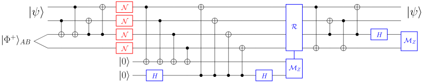
To benchmark the performance of the proposed scheme, we have chosen the following QED+QT schemes. Firstly, for the recurrence-based QED+QT scheme (QED+QT 1), we carry out two single-round distillations to obtain two less noisy EPR pairs from four noisy EPR pairs. Secondly, for the QSC-based QED+QT scheme (QED+QT 2), we choose the stabilizer operators of and to apply error-detection to a set of four noisy EPR pairs. Finally, we also include the QSC-IE scheme having the stabilizer operators of and as our benchmark. The uncoded QBER is given by , which means that any error experienced by any logical qubit within the two qubits is considered as an error. The resultant QBER is portrayed in Fig. 8(a), while the yield is quantified in Fig. 8(b).

Let us evaluate the QBER and the yield of the recurrence-based QED+QT scheme by considering a pair of identical error-detection schemes based on Fig. 3. We can determine the success probability of this arrangement by taking the square of (14) of Proposition 1, since the legitimate quantum state of the logical qubit is retained only when both error-detection schemes make the correct decision. Consequently, the success probability is given by
| (20) |
Similarly, the yield can be obtained by taking the square of of (15) in Proposition 1 and then by normalizing it by , where we obtain
| (21) |
The QBER and yield results in (20) and (21) are depicted in Fig. 8(a) and 8(b), respectively, as ‘QED+QT 1’.
In Fig. 8(a), our proposed scheme outperforms the recurrence-based QED+QT scheme (QED+QT 1) for , while exhibiting an identical QBER to the QSC-based QED+QT scheme (QED+QT 2) and QSC-IE. Furthermore, we also observe the probability threshold of , which is portrayed using vertical black dotted line, for the proposed error-detection scheme in Fig. 7. However, observe in Fig. 8(b) that the recurrence-based QED+QT scheme attains a better yield. The reason is that the recurrence-based QED+QT scheme exhibits a weaker error-detection capability than the other schemes. More specifically, each round of recurrence QED is only capable of detecting a single error. By contrast, for the QSC-based QED+QT, QSC-IE, and also our proposed schemes, they are all capable of detecting a single error and also a single error. Consequently, the recurrence-based QED+QT scheme often makes the wrong decision of retaining the erroneous logical qubits, instead of discarding them, which is reflected in higher QBER result. However, these QBER and yield results can be achieved by utilizing fewer CNOT gates.
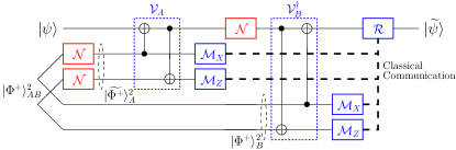
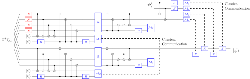
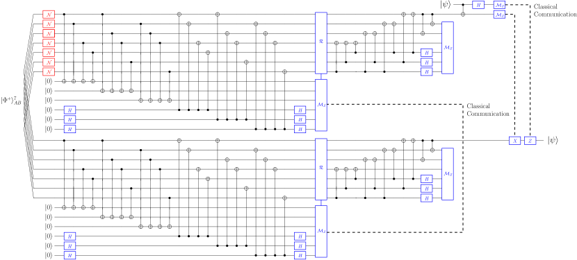
Additionally, as shown in Fig. 7, the total number of CNOT gates required by the entire proposed error-detection scheme is eight. As a comparison, the QSC-based QED+QT scheme requires a total of 28 CNOT gates, namely 16 for the stabilizer measurements, 10 for the quantum inverse encoder, and two for quantum teleportation. The quantum circuit of the QSC-based QED+QT scheme is portrayed in Fig. 9. Meanwhile, the QSC-IE scheme, whose quantum circuit is portrayed in Fig. 10, requires a total of 16 CNOT gates, namely four for the quantum encoder, eight for the stabilizer measurements, and four for the quantum inverse encoder. Therefore, our proposed scheme requires significantly fewer CNOT gates while offering an identical QBER and yield.
We summarize all the resources required by the various quantum communication schemes of Fig. 8 in Table III. All the schemes considered in Table III – except for the QED+QT 1 scheme – attain identical QBER and yield. To achieve this, our proposed scheme requires fewer pre-shared EPR pairs, fewer classical channel uses, and fewer CNOT gates compared to the QSC-based QED+QT scheme. By contrast, with the same number of quantum channel uses, our proposed scheme requires more pre-shared EPR pairs and more classical channel uses than the QSC-IE scheme, while utilizing fewer CNOT gates.
| Scheme | Quantum channel use | Logical qubits | EPR pairs | Classical channel use | CNOT |
| QED+QT 1 | 4 | 2 | 4 | 6 | 4 |
| QED+QT 2 | 4 | 2 | 4 | 6 | 28 |
| QSC-IE | 4 | 2 | 1 | 0 | 16 |
| Proposed | 4 | 2 | 2 | 2 | 8 |
Remark.
While providing an identical QBER and yield to the QSC-based QED+QT and QSC-IE schemes, our error-detection scheme always requires fewer CNOT gates.
V Error-Correction Scheme
Error-detection schemes provide dynamic yields, since they rely on a discard-and-retain action of the operator , while error-correction schemes provide a constant yield, since they attempt to recover the legitimate quantum state of the logical qubits from the received encoded state. Therefore, a modification of Definition 10 and 11 is required in order to accurately evaluate the performance of the proposed error-correction scheme.
Definition 4.
The success probability of the proposed error-correction scheme is defined as the sum of the conditional probabilities , i.e. the sum of the probabilities that the error-recovery operator successfully applies based on the syndrome value :
| (22) |
where the relationship between and the QBER can be expressed as .
Definition 5.
The yield of the proposed error-correction scheme is defined as the ratio of logical qubits to the uses of the quantum channel :
| (23) |
while its goodput is similarly defined to Definition 12.
Let us now consider the quantum encoder and decoder of Fig. 11. To investigate its error-correction performance, we have to check first that the scheme of Fig. 11 is capable of discriminating all the single-qubit error patterns based on the measured syndrome values. In Fig. 11, we can observe that the overall scheme requires six noisy pre-shared EPR pairs, which means that we have a six-bit syndrome string denoted by , where the indices represent the EPR pair starting from the top. Therefore, for each of the single-qubit error patterns, we can evaluate the syndrome string and the associated error recovery operator, as shown in Table IV. Observe that the first three elements of the syndrome string are exclusively used for identifying errors, which are obtained from basis measurements . By contrast, the last three elements are used for identifying errors, which are obtained from basis measurements . Finally, the errors can be identified based on the combination of and .
| Error pattern | Syndrome | Error recovery | Error pattern | Syndrome | Error recovery |
|---|---|---|---|---|---|
For the quantum depolarizing channel, we have a total of error patterns represented by the total number of combinations in terms of bit-flip , phase-flip , as well as simultaneous bit-flip and phase-flip errors, where we observe a total of correctable error patterns. After scrutinizing all error patterns, we obtain the Pauli weight distribution of the error patterns in quantum depolarizing channels as follows: one error pattern is the all-identity operator (weight = ); 21 error patterns having weight = 1; 42 error patterns having weight = 2; 252 error patterns having weight = 3; 609 error patterns having weight = 4; 1281 having weight = 5; 1428 error patterns having weight = 6; 462 error patterns having weight = 7. This distribution is identical to that of a QSC-based QED+QT scheme utilizing the stabilizer operators of the Steane code. Given that we have , the success probability of the proposed error-correction scheme of Fig. 11 in quantum depolarizing channels is given by
| (24) |
where is the Pauli weight of the correctable error patterns. Notice that our proposed scheme is capable of correcting not only the error patterns exhibiting a Pauli weight = 1, but also several error patterns having higher Pauli weights. This is due to the degeneracy property of quantum information inherited by QECCs. Naturally, by exploiting the degeneracy property, the QBER of quantum error-control schemes, including our proposed schemes, can be improved.
Let us now compare the QBER of our proposed scheme to those of the QSC-based QED+QT and QSC-IE scheme. Indeed for a fair comparison, we do not consider the recurrence-based QED+QT scheme, since it is an error-detection scheme, not an error-correction one. For the QSC-based QSC+QT scheme, we utilized the stabilizer operators of Steane code [36, 17] over seven noisy pre-shared EPR pairs. By contrast, for the QSC-IE scheme, we also utilized the stabilizer operators of Steane code, but only by using three noisy pre-shared EPR pairs [31]. The resultant QBER of the proposed scheme is depicted in Fig. 12(a), which is identical to the QBER of the QSC-based QED+QT and QSC-IE schemes employing the stabilizer operators of the Steane code. Here, we obtain the probability threshold of for the proposed error-correction scheme in Fig. 11, which is indicated by the vertical black dotted line in Fig. 12(a). The proposed, the QSC-based QED+QT, and the QSC-IE schemes all provide a yield of , since they perform error-correction, instead of error-detection. Consequently, as reported in Fig. 12(b), the proposed error-correction scheme also provides an identical goodput to the QSC-based QED+QT and QSC-IE schemes.
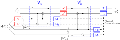
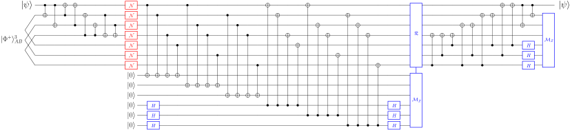
As for their quantum circuit implementations, our proposed scheme requires a total of 22 CNOT gates as seen in Fig 11. By contrast, the QSC-based QED+QT scheme requires a total of 71 CNOT gates, namely 48 for stabilizer measurements, 22 for the quantum inverse encoder, and one for quantum teleportation. To elaborate a little further on the quantum circuit implementation required for performing QED+QT scheme using the stabilizer operators of Steane code, please refer to Fig. 13. Meanwhile, the QSC-IE scheme requires a total of 43 CNOT gates, namely eight for quantum encoder, 24 for the stabilizer measurements, and 11 for quantum inverse encoder. To provide a clear picture about the quantum circuit implementation of the QSC-IE scheme using the stabilizer operators of Steane code, please refer to Fig. 14. We summarize all the physical resources required for performing the error correction schemes to achieve reliable quantum communication in the presence of noisy pre-shared EPR pairs in Table V.
| Scheme | Quantum channel use | Logical qubits | EPR pairs | Classical channel use | CNOT |
| QED+QT | 7 | 1 | 7 | 8 | 71 |
| QSC-IE | 7 | 1 | 3 | 0 | 43 |
| Proposed | 7 | 1 | 6 | 6 | 22 |
Remark.
While attaining an identical QBER and yield to that of QSC-based QED+QT scheme, our proposed arrangement requires fewer pre-shared EPR pairs, fewer classical channel uses, and fewer CNOT gates. However, the proposed arrangement requires more pre-shared EPR pairs and more classical channel uses than the QSC-IE scheme in exchange for fewer CNOT gates and the same number of quantum channel uses.
VI Discussion: A Quantum Computing Perspective
In the previous sections, we have shown the advantages of our proposal in quantum communication applications. In this section, we demonstrate that the proposed scheme can also be adopted for quantum computing applications. In quantum computing applications, the quantum information is usually protected with the aid of noise-free auxiliary qubits, which may also take form of pre-shared entanglement [23, 24, 19, 20, 21, 25]. A prime example is constituted by the family of entanglement-assisted quantum stabilizer codes (EA-QSCs). Compared to the conventional QSCs, which are unassisted by noise-free pre-shared entanglement, EA-QSCs offer an error-correction capability improvement. This is reminiscent of having an additional error-free side channel between the transmitter and the receiver in the classical domain. The argument that we can always have noise-free pre-shared entanglement relies on the assumption that EPR pairs can be created abundantly and quantum entanglement distillation can be applied to them. The concept of EA-QSCs is favourable in the realms of quantum computation, since the EA-QSCs can be readily amalgamated both with transversal implementation of quantum gates [37, 38] as well as with magic state distillation [39] for creating a universal set of fault-tolerant quantum gates. In the following, we propose an error-correction scheme that outperforms the state-of-the-art EA-QSC.
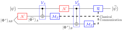
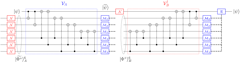
Any EA-QSC can be defined as , where is the number of physical qubits, is the number of logical qubits, is the minimum distance of the code, and is the number of noise-free pre-shared maximally-entangled qubits. The error-detection and error-correction capability of any EA-QSC can be determined by its minimum distance . An EA-QSC exhibiting a minimum distance is capable of detecting quantum errors or correcting quantum errors. Based on the quantum Singleton bound of EA-QSCs [23], there exists a EA-QSC capable of correcting a single-qubit error , which encodes one logical qubit into three physical qubits with the aid of two noise-free pre-shared maximally-entangled qubits . This specific code is denoted by . In the following, we will show that by utilizing two noise-free pre-shared EPR pairs, instead of error-correction, we can achieve error elimination, implying that in this specific context, we can always obtain a noise-free logical qubit.
Let us now discuss our proposed scheme portrayed in Fig. 15(a), which is rearranged into Fig. 15(b) for facilitating our analysis. The quantum channel in Fig. 15(a) and 15(b) represents a quantum channel contaminating the logical qubit. According to Fig. 15(b), the quantum encoder is represented by the following unitary matrix:
| (25) |
while the quantum decoder is described by the following unitary matrix:
| (26) |
It can be readily verified that the reversible property is satisfied, i.e. we have .
Upon denoting the density matrix of the initial global quantum state of by , the proposed scheme can be formulated with the aid of the following supermap:
| (27) |
where is the Kraus operator describing the quantum channel, while and represent the unitary matrices of (25) and (26). Therefore, (27) can be rewritten as:
| (28) |
After the decoding operation, we perform the measurement of the EPR pairs. Observe that we can apply basis measurement to the first EPR pair and basis measurement to the second EPR pair for determining the type of Pauli error experienced by the logical qubit . To elaborate a little further, we design a scheme so that requiring a joint measurement of the EPR pairs can be avoided to reduce the complexity of the quantum encoder and decoder. We combine the classical bits of and of Fig. 15(b) to determine the error recovery operator .
| Error recovery | ||
| 0 | 0 | |
| 1 | 0 | |
| 1 | 1 | |
| 0 | 1 |
To expound a little further, let us denote the syndrome string as , where is obtained from the measurement of the first EPR pair in basis and is gleaned from the measurement of the second EPR pair in basis. The error recovery operator associated with the syndrome value is portrayed in Table VI. Finally, it may be inferred from (28), that after the error recovery operator of Fig. 15(a), we always obtain the legitimate quantum state of the logical qubit. Hence, we have demonstrated that with the aid of two noise-free EPR pairs, instead of correcting a single-qubit achievable by an EA-QSC, we can always recover a noise-free logical qubit. Observe that when we replace the quantum channel by realistic noisy quantum Pauli gates, we can modify the LUT of Table VI to benefit from the noise-free operation of the quantum Pauli gates.
VII Conclusions and Future Research
In this treatise, we have conceived a novel direct quantum communication scheme using noisy pre-shared EPR pairs. Conventionally, achieving a reliable quantum communication tends to rely on the consecutive steps of QED followed by quantum teleportation (QED+QT). One of the salient benefits that we can offer is the elimination of the long communication delay imposed by the aforementioned consecutive steps, despite relying on noisy pre-shared EPR pairs. Additionally, our proposed schemes offer better QBER than the recurrence-based QED+QT schemes and provide identical QBER and yield to the QSC-based QED+QT schemes. Moreover, compared to the QSC-based QED+QT schemes, our proposal requires fewer pre-shared entanglement, fewer classical channel uses, and fewer CNOT gates. We have also included the quantum stabilizer code using imperfect pre-shared entanglement (QSC-IE) scheme as our benchmark. Our results show that despite attaining the same level of error-detection and error-correction capability, our proposed scheme requires more pre-shared EPR pairs and more classical channel uses, however, in exchange for fewer CNOT gates requirement and the same number of quantum channel uses. Finally, we have also compared our proposed scheme to EA-QSC, which requires noise-free pre-shared EPR pairs. Again, EA-QSCs require joint eigenvalue measurements relying on all the qubits gleaned from the EPR pairs for performing error-correction. Despite relying only on the local measurements of the EPR pairs and classical communications, we can always obtain a noise-free logical qubit using our proposed scheme.
In our future research, we are interested in finding a systematic way of constructing the quantum encoder and decoder pair. In fact, we found that an arbitrary quantum encoder and decoder pair cannot always satisfy the reversible property of (6). Therefore, the sufficient and necessary conditions of generating the quantum encoder and decoder pair should be found. Since our proposed scheme performs identically to the QSC-based QED+QT schemes, it remains to be shown whether a wider range of QSCs can be directly embedded into our scheme. Furthermore, since our proposed scheme requires fewer CNOT gates compared to all state-of-the-art schemes, we are also interested in investigating the performance of the quantum communication schemes under additional realistic assumption of having imperfect quantum gates as well as imperfect measurements and looking at the possibility of creating a fault-tolerant quantum communication protocol.
VIII Appendix A: Proof of Proposition 1
By exploiting the quantum depolarizing channel model of Section II and by utilizing the expressions of (IV-A), (7) can be reformulated as shown in (29), where is the density matrix of the logical qubit and we assume that the quantum depolarizing channels experienced by and exhibit an identical depolarizing probability .
| (29) |
After the decoding, a measurement in the basis of the EPR pair shared between and is performed. Every time we find a disagreement in the classical measurement results from the EPR pair , the associated logical qubit is discarded, otherwise, it is retained. We note that the syndrome value of is obtained if the EPR pair is in the quantum state or , while the EPR pair in the state or gives us a syndrome value of . Hence, the probability of retaining the logical qubit is equal to the probability of obtaining the syndrome value . Based on these considerations and by accounting for (29), we can determine the probability of obtaining the syndrome value :
| (30) |
which is obtained from the following error operators . Then, based on this set of error operators, we can determine the probability of obtaining the syndrome value of and obtain the legitimate quantum state of the logical qubit :
| (31) |
which is obtained from the following error operators . More specifically, the error operator imposed by the quantum channels is transformed into an error operator at the output of the quantum decoder of Fig. 3. Consequently, we have the final quantum state of . Since the measurement of the EPR pair is performed in basis, we obtain the syndrome value of , while retaining the legitimate quantum state of the logical qubit . Finally, the success probability of the scheme presented in Fig. 3 can be determined according to Definition 10 as follows:
| (32) |
which gives us an approximately linear performance improvement over the uncoded QBER as a function of . By accounting for Definition 11, the yield is and the proof follows.
IX Appendix B: Proof of Proposition 2
After applying the first CNOT of the decoder of Fig. 6, we can determine the probability of obtaining the syndrome value from the first EPR pair as follows:
| (33) |
If , we discard the logical qubit. If , the first-two quantum depolarizing channels are reduced into a single depolarizing channel having the following Kraus operators:
| (34) |
Now, by applying the second CNOT of the decoder of Fig. 6, we can determine the probability of obtaining the syndrome value from the second EPR pair as follows:
| (35) |
If , we discard the logical qubit, while If , we retain the logical qubit. Therefore, the probability of arriving at the legitimate quantum state and measuring the syndrome value is given by
| (36) |
X Appendix C: Proof of Proposition 3
Similar to the proof of Proposition 1, By exploiting the error model of Section II and relying on the quantum encoder and decoder of Fig. 7, the supermap of (7) can be readily obtained. After the decoding operation, the first EPR pair is measured in the basis while the second one in the basis. Let us distinguish the components of the syndrome string in (8) according to the basis used for the measurement. Specifically, let us denote the syndrome component obtained when the second EPR pair is measured in the basis by , while the syndrome component obtained when the first EPR pair is measured in the basis by . The overall syndrome string is . Since no error operators exhibiting even numbers of errors and even numbers of errors can be detected, which gives us the syndrome vector of , the probability we retain the logical qubits is equal to the sum of the probabilities of all these possible error patterns resulting in the syndrome vector of . After observing error patterns, we found 64 error patterns that generate the syndrome vector of : one all-identity error pattern (weight = 0); 18 error patterns having Pauli weight = 2; 24 error patterns having Pauli weight = 3; and 21 error patterns having Pauli weight = 4. Therefore, by accounting for (7), we have
| (37) |
where . However, from all of those error patterns, only four are actually associated with the legitimate quantum state of the logical qubits, which are . Hence, the probability of obtaining the legitimate quantum state while measuring is given by
| (38) |
References
- [1] H. J. Kimble, “The Quantum Internet,” Nature, vol. 453, no. 7198, pp. 1023–1030, 2008.
- [2] M. Caleffi, A. S. Cacciapuoti, and G. Bianchi, “Quantum Internet: From communication to distributed computing!,” in Proceedings of the 5th ACM International Conference on Nanoscale Computing and Communication, pp. 1–4, 2018.
- [3] S. Wehner, D. Elkouss, and R. Hanson, “Quantum Internet: A vision for the road ahead,” Science, vol. 362, no. 6412, 2018.
- [4] C. Wang, A. Rahman, and R. Li, “Applications and use cases for the Quantum Internet,” Internet Draft draft-wang-qirg-quantum-internet-use-cases-04, Internet Engineering Task Force, Mar. 2020. Work in Progress.
- [5] M. Razavi, “Multiple-access quantum key distribution networks,” IEEE Transactions on Communications, vol. 60, no. 10, pp. 3071–3079, 2012.
- [6] D. Cuomo, M. Caleffi, and A. S. Cacciapuoti, “Towards a distributed quantum computing ecosystem,” IET Quantum Communication (Invited Paper), vol. 1, no. 1, pp. 3–8, 2020.
- [7] M. Caleffi, D. Chandra, D. Cuomo, S. Hassanpour, and A. S. Cacciapuoti, “The rise of the Quantum Internet,” Computer, vol. 53, no. 6, pp. 67–72, 2020.
- [8] Z. Sun, L. Song, Q. Huang, L. Yin, G. Long, J. Lu, and L. Hanzo, “Toward practical quantum secure direct communication: A quantum-memory-free protocol and code design,” IEEE Transactions on Communications, vol. 68, no. 9, pp. 5778–5792, 2020.
- [9] A. S. Cacciapuoti, M. Caleffi, F. Tafuri, F. S. Cataliotti, S. Gherardini, and G. Bianchi, “Quantum Internet: Networking challenges in distributed quantum computing,” IEEE Network, vol. 34, no. 1, pp. 137–143, 2019.
- [10] A. S. Cacciapuoti, M. Caleffi, R. Van Meter, and L. Hanzo, “When entanglement meets classical communications: Quantum teleportation for the Quantum Internet,” IEEE Transactions on Communications (Invited Paper), vol. 68, no. 6, pp. 3808–3833, 2020.
- [11] M. A. Nielsen and I. L. Chuang, Quantum computation and quantum information. Cambridge University Press, 2000.
- [12] G. Cariolaro and G. Pierobon, “Performance of quantum data transmission systems in the presence of thermal noise,” IEEE Transactions on Communications, vol. 58, no. 2, pp. 623–630, 2010.
- [13] C. E. Shannon, “A mathematical theory of communication,” The Bell System Technical Journal, vol. 27, no. 3, pp. 379–423, 1948.
- [14] P. W. Shor, “Scheme for reducing decoherence in quantum computer memory,” Physical Review A, vol. 52, no. 4, 1995.
- [15] A. R. Calderbank and P. W. Shor, “Good quantum error-correcting codes exist,” Physical Review A, vol. 54, no. 2, 1996.
- [16] R. Laflamme, C. Miquel, J. P. Paz, and W. H. Zurek, “Perfect quantum error correcting code,” Physical Review Letters, vol. 77, no. 1, 1996.
- [17] D. A. Lidar and T. A. Brun, Quantum error correction. Cambridge University Press, 2013.
- [18] Z. Babar, D. Chandra, H. V. Nguyen, P. Botsinis, D. Alanis, S. X. Ng, and L. Hanzo, “Duality of quantum and classical error correction codes: Design principles and examples,” IEEE Communications Surveys & Tutorials, vol. 21, no. 1, pp. 970–1010, 2018.
- [19] Y. Fujiwara, D. Clark, P. Vandendriessche, M. De Boeck, and V. D. Tonchev, “Entanglement-assisted quantum low-density parity-check codes,” Physical Review A, vol. 82, no. 4, 2010.
- [20] M. M. Wilde and J. M. Renes, “Quantum polar codes for arbitrary channels,” in Proceedings of the IEEE International Symposium on Information Theory (ISIT), pp. 334–338, IEEE, 2012.
- [21] M. M. Wilde, M.-H. Hsieh, and Z. Babar, “Entanglement-assisted quantum turbo codes,” IEEE Transactions on Information Theory, vol. 60, no. 2, pp. 1203–1222, 2013.
- [22] D. Chandra, Z. Babar, H. V. Nguyen, D. Alanis, P. Botsinis, S. X. Ng, and L. Hanzo, “Quantum coding bounds and a closed-form approximation of the minimum distance versus quantum coding rate,” IEEE Access, vol. 5, pp. 11557–11581, 2017.
- [23] T. A. Brun, I. Devetak, and M.-H. Hsieh, “Correcting quantum errors with entanglement,” Science, vol. 314, no. 5798, pp. 436–439, 2006.
- [24] I. Devetak, T. A. Brun, and M.-H. Hsieh, “Entanglement-assisted quantum error-correcting codes,” in New Trends in Mathematical Physics: Selected Contributions of the 15th International Congress on Mathematical Physics, pp. 161–172, Springer, 2009.
- [25] M. Grassl, “Entanglement-assisted quantum communication beating the quantum Singleton bound,” in Proceedings of the 16th Asian Quantum Information Science Conference (AQIS), pp. 20–21, 2016.
- [26] C. H. Bennett, H. J. Bernstein, S. Popescu, and B. Schumacher, “Concentrating partial entanglement by local operations,” Physical Review A, vol. 53, no. 4, 1996.
- [27] C. H. Bennett, G. Brassard, S. Popescu, B. Schumacher, J. A. Smolin, and W. K. Wootters, “Purification of noisy entanglement and faithful teleportation via noisy channels,” Physical Review Letters, vol. 76, no. 5, p. 722, 1996.
- [28] C. H. Bennett, D. P. DiVincenzo, J. A. Smolin, and W. K. Wootters, “Mixed-state entanglement and quantum error correction,” Physical Review A, vol. 54, no. 5, 1996.
- [29] R. Matsumoto, “Conversion of a general quantum stabilizer code to an entanglement distillation protocol,” Journal of Physics A: Mathematical and General, vol. 36, no. 29, 2003.
- [30] C. H. Bennett, G. Brassard, C. Crépeau, R. Jozsa, A. Peres, and W. K. Wootters, “Teleporting an unknown quantum state via dual classical and Einstein-Podolsky-Rosen channels,” Physical Review Letters, vol. 70, no. 13, 1993.
- [31] C.-Y. Lai and T. A. Brun, “Entanglement-assisted quantum error-correcting codes with imperfect ebits,” Physical Review A, vol. 86, no. 3, 2012.
- [32] D. Chandra, Z. Babar, S. X. Ng, and L. Hanzo, “Near-hashing-bound multiple-rate quantum turbo short-block codes,” IEEE Access, vol. 7, pp. 52712–52730, 2019.
- [33] H. V. Nguyen, Z. Babar, D. Alanis, P. Botsinis, D. Chandra, S. X. Ng, and L. Hanzo, “EXIT-chart aided quantum code design improves the normalised throughput of realistic quantum devices,” IEEE Access, vol. 4, pp. 10194–10209, 2016.
- [34] D. Chandra, Z. Babar, H. V. Nguyen, D. Alanis, P. Botsinis, S. X. Ng, and L. Hanzo, “Quantum topological error correction codes are capable of improving the performance of Clifford gates,” IEEE Access, vol. 7, pp. 121501–121529, 2019.
- [35] R. Cane, D. Chandra, S. X. Ng, and L. Hanzo, “Mitigation of decoherence-induced quantum-bit errors and quantum-gate errors using Steane’s code,” IEEE Access, vol. 8, pp. 83693–83709, 2020.
- [36] A. Steane, “Multiple-particle interference and quantum error correction,” Proceedings of the Royal Society of London - Series A: Mathematical, Physical and Engineering Sciences, vol. 452, no. 1954, pp. 2551–2577, 1996.
- [37] J. Preskill, “Reliable quantum computers,” Proceedings of the Royal Society of London - Series A: Mathematical, Physical and Engineering Sciences, vol. 454, no. 1969, pp. 385–410, 1998.
- [38] E. T. Campbell, B. M. Terhal, and C. Vuillot, “Roads towards fault-tolerant universal quantum computation,” Nature, vol. 549, no. 7671, pp. 172–179, 2017.
- [39] S. Bravyi and A. Kitaev, “Universal quantum computation with ideal Clifford gates and noisy ancillas,” Physical Review A, vol. 71, no. 2, 2005.
![[Uncaptioned image]](/html/2012.11982/assets/x20.png) |
Daryus Chandra (S’15, M’20) received the M.Eng. degree in electrical engineering from Universitas Gadjah Mada, Indonesia, in 2014 and the Ph.D. degree in electronics and electrical engineering from University of Southampton, UK, in 2020. He was a research fellow with the Future Communications Laboratory, University of Naples Federico II, Italy. Currently, he is a research fellow with the Next-Generation Wireless Research Group, University of Southampton, UK. His current research interests include classical and quantum error-correction codes, quantum information, and quantum communications. |
![[Uncaptioned image]](/html/2012.11982/assets/x21.png) |
Angela Sara Cacciapuoti (M’10, SM’16) is an Associate Professor at the University of Naples Federico II, Italy. Since July 2018, she held the national habilitation as “Full Professor” in Telecommunications Engineering. Her work has appeared in first tier IEEE journals and she has received different awards, including the elevation to the grade of IEEE Senior Member in 2016. Currently, Angela Sara serves as Area Editor for IEEE Communications Letters, and as Editor/Associate Editor for the journals: IEEE Trans. on Communications, IEEE Trans. on Wireless Communications, IEEE Trans. on Quantum Engineering, IEEE Network and IEEE Open Journal of Communications Society. She was a recipient of the 2017 Exemplary Editor Award of the IEEE Communications Letters. In 2016 she has been an appointed member of the IEEE ComSoc Young Professionals Standing Committee. From 2017 to 2018, she has been the Award Co-Chair of the N2Women Board. From 2017 to 2020, she has been the Treasurer of the IEEE Women in Engineering (WIE) Affinity Group of the IEEE Italy Section. In 2018, she has been appointed as Publicity Chair of the IEEE ComSoc Women in Communications Engineering (WICE) Standing Committee. And since 2020, she is the vice-chair of WICE. Her current research interests are mainly in Quantum Communications, Quantum Networks and Quantum Information Processing. |
![[Uncaptioned image]](/html/2012.11982/assets/x22.png) |
Marcello Caleffi (M’12, SM’16) is associate professor with DIETI Department, University of Naples Federico II. Previously, he was with the Broadband Wireless Networking Laboratory, Georgia Institute of Technology, Atlanta, GA, USA, and also with the NaNoNetworking Center in Catalunya (N3Cat), Universitat Politecnica de Catalunya (UPC), Barcelona, as visiting researcher. Since July 2018, he held the Italian National Habilitation as full professor in telecommunications engineering. He currently serves as associate editor/associate technical editor for IEEE Communications Magazine, IEEE Trans. on Wireless Communications, IEEE Trans. on Quantum Engineering and IEEE Communications Letters. In 2017, he has been appointed as a Distinguished Lecturer for the IEEE Computer Society. In December 2018, he has been an appointed member of the IEEE New Initiatives Committee. |
![[Uncaptioned image]](/html/2012.11982/assets/x23.png) |
Lajos Hanzo (FIEEE’04) received his Master degree and Doctorate in 1976 and 1983, respectively from the Technical University (TU) of Budapest. He was also awarded the Doctor of Sciences (DSc) degree by the University of Southampton (2004) and Honorary Doctorates by the TU of Budapest (2009) and by the University of Edinburgh (2015). He is a Foreign Member of the Hungarian Academy of Sciences and a former Editor-in-Chief of the IEEE Press. He has served several terms as Governor of both IEEE ComSoc and of VTS. He has published 1970 contributions at IEEE Xplore, 19 Wiley-IEEE Press books and has helped the fast-track career of 123 PhD students. Over 40 of them are Professors at various stages of their careers in academia and many of them are leading scientists in the wireless industry. He is also a Fellow of the Royal Academy of Engineering (FREng), of the IET and of EURASIP. (http://www-mobile.ecs.soton.ac.uk, https://en.wikipedia.org/wiki/Lajos-Hanzo) |