-channel comb filtering and lasing in -symmetric superstructures
Abstract
A comb spectrum generating device based on Bragg grating superstructures with gain and loss is suggested in this paper. It includes a comprehensive analysis of the device formulation, generation and manipulation of the comb spectrum with a number of degrees of freedom such as duty cycle, sampling period and gain-loss parameter. For applications such as RF traversal filters and tunable multi-wavelength laser sources, the reflected intensities of the comb resulting from the superstructures should have uniform intensities, and this is guaranteed by optimizing the physical length of the device, gain and loss in the unbroken -symmetric regime. Alternatively, it can be accomplished by reducing the duty cycle ratio of the superstructure to extremely small values in the broken -symmetric regime. Such a customization will degrade the reflectivity of the conventional grating superstructures, while it gives rise to narrow spectral lines with high reflectivity in the proposed system. Remarkably, combs with an inverted envelope are generated for larger values of gain and loss.
I Introduction
Optical frequency comb (OFC) is a widely used notion to denote a spectral source featuring a series of isolated spectral lines, which are uniformly spaced Pilozzi2017 . OFCs are readily built from a diverse range of all-optical building blocks, including mode locked fiber lasers jones2000carrier ; fortier201920 ; jin2006absolute , ring resonators del2007optical ; Herr2014 , sampled or superstructured fiber Bragg gratings (SFBGs) Dong2006 ; Lee2003 ; Lee2004 ; Lee2004a ; Li2003 ; Loh1999 ; Navruz2008 ; Zhang2019 ; Zou2006 , -symmetric topological structures Pilozzi2017 and so forth. OFCs have broad spectral span (with or without uniform amplitudes) Li2003 , and due to this inherent property, the footprints of OFCs are found in both classical and quantum optical applications such as telecommunication systems Dong2006 ; Lee2003 ; Lee2004 ; Lee2004a ; Li2003 ; Loh1999 ; Navruz2008 ; Zhang2019 ; Zou2006 , ultrafast spectroscopy Gohle2005 , generation of attosecond pulses baltuvska2003attosecond , quantum computing Pfister2020 , and optical frequency metrology udem2002optical . Precise control over the spectral characteristics of OFCs is one of the challenging aspects of scientific investigation jayaraman1993theory ; Li2003 ; Zou2006 ; fortier201920 besides the scalability and on-chip integration of these OFC sources baltuvska2003attosecond . For an outstanding contribution to the generation of OFC and its application to laser-based precision spectroscopy holzwarth2000optical , Hall and Hansch were awarded Nobel prize back in 2005 hall2006nobel ; hansch2006nobel . Since then, investigations on the generation, control and applications of OFCs in various fields remain as one of the active areas of research fortier201920 .
Research interest on modern light wave communication systems is primarily targeted at effective utilization of the available channel bandwidth via judicious design of multi channel devices that would simultaneously handle many independent frequencies Dong2006 ; Lee2003 ; Lee2004 ; Lee2004a ; Li2003 ; Loh1999 ; Navruz2008 ; Zhang2019 ; Zou2006 . In particular, OFCs based on SFBGs are fascinating for the reasons that they are much compact, less complex and they can be employed to handle multi-channel functionalities like multi-wavelength lasers jayaraman1993theory ; ishii1993multiple ; Sourani2019 , broadband dispersion compensators Li2003 ; Lee2003 ; Lee2004a , transverse-load sensing devices Shu2003 , space-tunable multi-channel notch filters Li2008 , etc. Previously, frequency comb spectrum in the presence of gain and loss was realized in a topological cascaded laser Pilozzi2017 and its realization in simple optical devices like fiber Bragg grating (FBG) still remains to be unexplored, which is a subject of the present investigation. Hence, it is important to critically analyze some of the fundamental concepts in designing a sampled grating structure alias superstructure in order to realize an OFC.
SFBG is a class of Bragg periodic structures, which is customized by not allowing any spatial variation in the refractive index (RI) of the core in between two adjacent samples Shu2003 . The samples are the regions of the core whose RI is permanently modulated by exposing them to intense UV exposure Li2003 ; Lee2003 . These samples are commonly referred as seed gratings since they form the basic building units of the structure Li2003 . Even though these basic building blocks are nothing but the conventional FBG structures (uniform or nonuniform), the SFBG exhibits some unique characteristics both in its structure and spectrum Eggleton1994 ; DeSterke1997 ; Eggleton1996 ; DeSterke1996 . Physically, the term sampling length () refers to the length of one sample and each sample is separated from its predecessor by a distance of (region of constant RI which is unexposed to UV). Hence, the period of the sampled grating is given by Zhang2019 ; Zou2006 ; Navruz2008 as shown in Fig. 1. The RI modulation of the individual sample is low, while the modulation of the grating depth of the overall structure is large DeSterke1995 ; DeSterke1996 . Also, the grating period () of the each FBG is very low ( 1 m) when compared to the sampling period (of the order of mm) erdogan1997fiber ; DeSterke1995 which results in a broad spectral span of the SFBG in contrast to the conventional FBG spectrum erdogan1997fiber ; DeSterke1995 ; DeSterke1997 .
The SFBG spectrum consists of many spectral lines (discrete) of high reflectivity and narrow width Zou2006 ; Lee2004 with each spectral line dedicated to one particular wavelength. The origin of such distinct spectrum can well be understood from the photonic band gap structure of a SFBG which possesses additional Bragg resonances or multiple band gaps that differentiate it from a conventional FBG DeSterke1995 ; DeSterke1997 ; Eggleton1996 . Thus higher order reflection modes become inevitable attributes of the SFBG spectrum Zhang2019 ; DeSterke1995 . The periodic nature of the inter-coupling parameter is yet another remarkable property of SFBGs DeSterke1997 ; DeSterke1995 . These features can be deemed as a precursor for realizing the multi-wavelength applications such as filters and others mentioned previously Li2003 .
Theoretical and experimental investigations on SFBGs are predominantly focused on improving the spectral characteristics such as increasing number of usable optical channels within the available bandwidths by reducing the channel spacing Navruz2008 ; Zhang2019 ; Zou2006 , and nonuniformity in the reflectivity (transmittivity) of the multi-channels ibsen1998sinc . These desirable attributes can be altered in accordance with the application of interest thanks to the availability of a wide range of sampling functions and flexible design methodologies in fabricating them ibsen1998sinc ; Lee2003 ; Li2003 . Broadly, these sampling windows can be categorized into amplitude sampling ibsen1998sinc , phase only sampling Li2003 ; Lee2003 , and hybrid sampling functions Navruz2008 . The uniform sampling technique is the simple and most straight forward approach in realizing SFBGs. The channels in the output spectrum of a uniformly sampled SFBG is likely to be nonuniform in their amplitude and their control remains a challenge. The SFBG mainly suffers from a decrease in the reflectivity with an increase in the number of channels in general Li2003 ; ibsen1998sinc ; Zou2006 ; Lee2003 . In the perspective of SFBGs without gain and loss, phase sampling techniques are widely incorporated to overcome this issue Lee2003 ; Lee2004 ; Navruz2008 .
Having concisely discussed the general concepts in the physical realization of SFBGs and the spectrum exhibited by them, we would like to note that all the above mentioned types of SFBG structures can be revisited again by researchers from the perspective of -symmetric structures. It is worthwhile to note that invoking the notion of -symmetry in a conventional FBG itself is of high scientific interest as it leads to novel non-Hermitian optical systems. We here take a step further ahead to establish -symmetry in a FBG superstructure which to our knowledge has no relevant scientific articles in literature to deal with. Realizing a -symmetric SFBG (PTSFBG) simply requires the modulation of RI of the seed grating (samples) to obey the -symmetric condition kottos2010optical ; el2007theory ; ruter2010observation ; sarma2014modulation ; lin2011unidirectional ; phang2013ultrafast ; miri2012bragg ; huang2014type ; govindarajan2018tailoring . It is well-known that the real and imaginary parts of the RI profile, respectively, need to be even and odd functions of propagation distance () for a -symmetric FBG (PTFBG) huang2014type ; lin2011unidirectional ; miri2012bragg . Prior to this work, linear spectrum of homogeneous miri2012bragg ; lin2011unidirectional ; kulishov2005nonreciprocal and inhomogeneous -symmetric gratings huang2014type ; lupu2016tailoring ; raja2020tailoring ; raja2020phase were investigated and the literature seems to lack any comprehensive investigation on the linear spectrum based on sampled PTFBG. Nevertheless, the demonstration of frequency comb in a supersymmetric (SUSY) DFB structure by Longhi longhi2015supersymmetric could be translated into the context of PTFBGs.
In this paper, we consider a SFBG with gain and loss under the expectation that the concept of reversal of direction of incidence kulishov2005nonreciprocal ; longhi2010optical ; phang2015versatile can possibly overcome the problem of reduction in reflectivity with an increase in the number of channels in contrast to the conventional SFBGs. Recently, discrete comb lasing modes were demonstrated in a topological -symmetric structure Pilozzi2017 . It should be noted that the broken -symmetric spectrum of any PTFBG feature a lasing behavior as reported by many authors raja2020tailoring ; phang2014impact ; huang2014type ; raja2020phase ; longhi2010pt . The natural question arises from these investigations is that whether it is possible to realize discrete and identical lasing modes with the aid of a SFBG operating in the broken -symmetric regime. We believe that the inherent nature of PTFBGs to offer multi-functionalities in different -symmetric regimes and the degrees of freedom it offers for the optimization of the desired spectral characteristics looks promising to engineer applications like filters and tunable laser sources in a SFBG structure.
With these motivations, we organize the article as follows. Section II describes the theoretical modeling of the PTSFBG in addition to the mathematical description of the system based on the transfer matrix method. In Sec. III, the comb filtering application of the system and its optimization with the grating parameters are presented in the unbroken -symmetric regime with a special emphasis on the right light incidence direction. The reflection-less wave transport phenomenon at the unitary transmission point is illustrated in Sec. IV. Section V illustrates the discrete multi channel lasing spectrum of the system in the broken -symmetric regime. The inferences from the previous sections are summarized in Sec. VI.
II Mathematical model
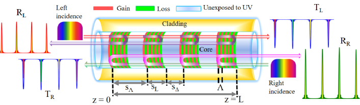
The description of the device is as follows: The structure is built up of (multiple) uniform PTFBG samples separated from each other by regions of core unexposed to UV. The RI distribution [] of the sample that includes the effect of -symmetry is given by
| (1) |
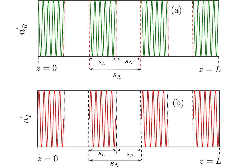
where stands for the constant RI of the core. The grating’s modulation strength is a complex entity whose real and imaginary parts are given by and , respectively. The notation in Eq. (1) refers to the grating period of each one of the gratings and it is indicated pictorially in Fig. 1. Each sample has a uniform length of value and it is followed by a region which is unexposed to UV (of length ). This behavior occurs cyclically in each sampling period (). It is important to point out that the system locally satisfies the -symmetric condition in each unit cell as well in the sampling length.
One unit cell is formed by having a real [ ] and imaginary [ ] modulation of the refractive index. The modulations and are depicted in Figs. 2(a) and 2(b). Each sample (uniform PTFBG) features a number of alternating regions of gain and loss.
It is useful to introduce an important parameter, namely duty cycle, which must be judiciously varied to achieve the desired spectrum erdogan1997fiber . Mathematically, the duty cycle is defined as the ratio of the length of the sample to the sampling period and it reads as
| (2) |
The PTSFBG proposed here is simply a uniform PTFBG in which the grating elements are stripped off in a periodic fashion. The resulting spectrum of the device can be found by the coupled mode theory (CMT) formalism. The transfer matrix method (TMM) stands out to be a first choice for theoretical physicists to analyze any complex FBG structure as it offers high accuracy and consumes less computation time over other techniques like the Gel-Fand–Levitan–Marchenko inverse scattering method, standard thin-film techniques or the Rouard theory of waveguides erdogan1997fiber , kashyap2009fiber . Each of these techniques has its own demerits and they are listed as below: First, the accuracy of the simulated results is limited by the rounding off errors in the computation in thin film based approaches. Also, it cannot fully characterize both the phase and amplitude responses of the complex type of gratings like nonuniform FBGs or superstructures. If the number of grating periods or the length of grating itself is large, the number of matrices also gets increased in Rouard method erdogan1997fiber . Thus, the computation becomes more complex and consumes more time. Nonetheless, the TMM is capable of addressing all these issues. Many types of physically realizable gratings have been fully characterized by employing this technique kashyap2009fiber . This is possible because of the fact that the TMM approach allows computation of the output field of a short section of the grating in a single iteration kashyap2009fiber . In the subsequent iterations, the resulting matrix that represents the output fields from the previous section is taken as the input matrix for a given section and this process is repeated for -number of cycles until the whole FBG is computed raja2020tailoring . Another important reason to choose TMM over other methods (for modeling SFBG) is that the direct analytical solutions are tedious to calculate if the number of samples is large erdogan1997fiber ; kashyap2009fiber . The direct integration of coupled mode equations may not work easily, if the sample contains abrupt phase jumps in its RI profile Li2003 ; erdogan1997fiber . Here, the mathematical relation between the number of samples (), sampling period () and the length of the whole device () can be given by,
| (3) |
Note that the total number of samples () can be varied as per the requirement by manipulating the sampling period, by fixing the length of the device (unless specified). Mathematically, let the matrices corresponding to these samples be assumed as , where . As an example, the PTSFBG with four samples () is shown in Fig. 1. To model this PTSFBG structure, the following routine is adopted:
All the samples in the above discussion are taken to be identical in the present investigation. Therefore, the matrices that represent these samples are also identical (). The regions unexposed to UV within each sample period are simply modeled by a phase matrix whose matrix elements are given by erdogan1997fiber
| (6) |
where and stand for the length of the region unexposed to UV and the operating wavelength, respectively.
Let and represent the input fields of the PTSFBG. Similarly, the output fields are given by and . Since the PTSFBG is built up of repeated units of samples followed by the core region unexposed to UV, the corresponding phase matrix () should be inserted in between the matrices representing the sample. Hence, the total electric field propagating through the device is given by
| (15) |
To find the matrices , , , and , each sample (of length ) is divided into number of piece-wise uniform sections (of length ). Thus, a sample is assumed to be a functional block formed by cascading number of sections of uniform PTFBG (). It is well known that cascading (physically) of different sections leads to multiplication of their respective transfer matrices (mathematically). Let () represent the matrix that corresponds to the section of the sample. Therefore,
| (16) |
The standard forms of for a uniform PTFBG have been already dealt by us in detail in our previous work raja2020phase and its final form is given by Eq. (17)
| (17) |
where . In Eq. (17), , , , and represent, respectively, the propagation constant, coupling, gain-loss and detuning coefficients of the piece-wise uniform section of the sample. For a uniform PTSFBG, these coefficients are same in all the sections and therefore,
| (18) |
Note that the model can be extended to number of samples by increasing the value of . In such a case, Eq. (15) can be rewritten as
| (27) |
It is well known that the reflection and transmission coefficients are nothing but the squared magnitudes of the amplitudes. These coefficients can be directly computed by applying the FBG boundary conditions, and in Eq. (15) and they read as lin2011unidirectional ; raja2020tailoring
| (28) |
The nature of -symmetry can be described based on the coupling and gain-loss coefficients as,
| (29) |
The Bragg wavelength of the sample is assumed to be nm and constant core index () is taken as throughout the paper.
III Unbroken -symmetric regime
It should be remembered that the output fields of uniform, chirped and other PTFBG devices consist of a single spectrum centered at the Bragg wavelength lin2011unidirectional ; raja2020tailoring . In contrast to these structures, the optical field (reflected and transmitted light) emerging out from a PTSFBG is a distinct one and commonly referred to as a comb spectrum for two reasons. First, the generated spectrum is characterized by periodic maxima (minima) or a serious of sharp spectral lines (resembling the teeth of a comb) jayaraman1993theory ; Li2003 . The other factor is that all these spectral lines are equidistant from each other in the wavelength domain and share a common phase evolution as a result of which the frequency dynamics of every mode in the comb spectrum is deterministic in nature fortier201920 . With this brief description, we directly look into the comb spectrum of a PTSFBG by following the routine proposed in Sec. II. Among the various spectral features (such as delay, dispersion, and so on), this article deals only with the variations in the reflection and transmission characteristics of a comb spectrum (with respect to the changes in the PTSFBG parameters) which are directly computed from Eq. (28)
III.1 Influence of -symmetry ()
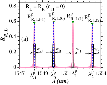
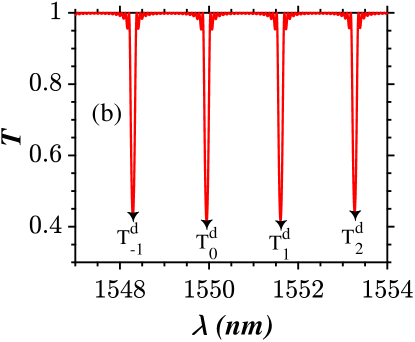
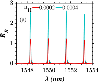
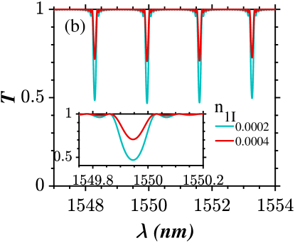
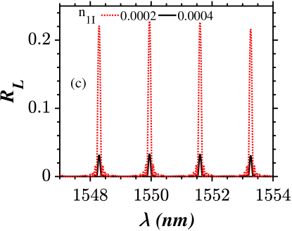
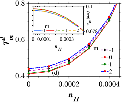
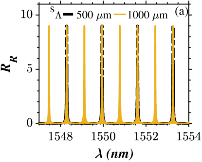
For simplicity, we first consider the spectrum with four modes () in the wavelength range to nm by assuming a sampling period of = 500 m and as shown in Fig. 3. The mode which occurs close to the Bragg wavelength features highest reflectivity (in general) and the detuning parameter corresponding to this mode is nearly zero () and hence the mode is designated as zeroth order mode (). On either side of zeroth order mode, higher order modes occur at discrete wavelengths corresponding to positive () and negative detuning regimes () and hence the modes in Fig. 3 are designated as , 0 , 1, and 2 rather than , 1, 2, and 3. The linear spectrum of a conventional sampled FBG is illustrated in Figs. 3(a) and 3(b) which confirm that the reflection and transmission from each channel always obey the condition , which suggests that the Hamiltonian of the system is conserved in the absence of -symmetry. But, with the inclusion of gain and loss, the reflectivity of each channel (indicated by subscript ) increases provided that the light launching direction is the right () direction as shown in Figs. 4(a) and 4(e). Nevertheless, when the incident direction is reversed, reflectivity () of all the channels gets reduced as seen in Figs. 4(c) and 4(f) when compared to the reflection spectrum shown in Fig. 3(a). The dips in the transmittivity () of the individual channels are clearly influenced by the presence of -symmetry as shown in Figs. 4(b) and 4(d). Moreover, the transmittivity at the side lobes of the individual channels gets reduced provided that is sufficiently large, say . Also, significant reduction in the FWHM of a single channel is observed which is shown in the inset of Figs. 4(b) and 4(d).
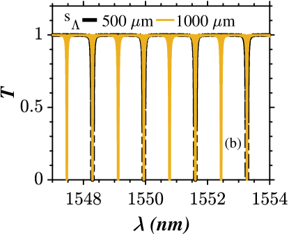
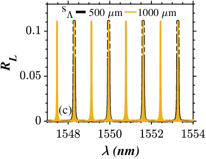
III.2 Variations in the sampling period ()
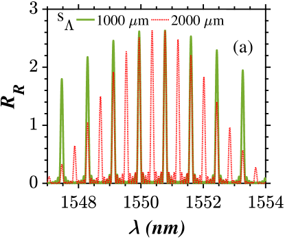
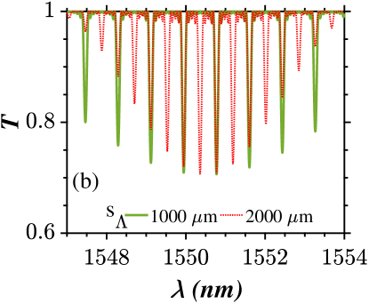
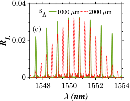
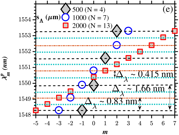
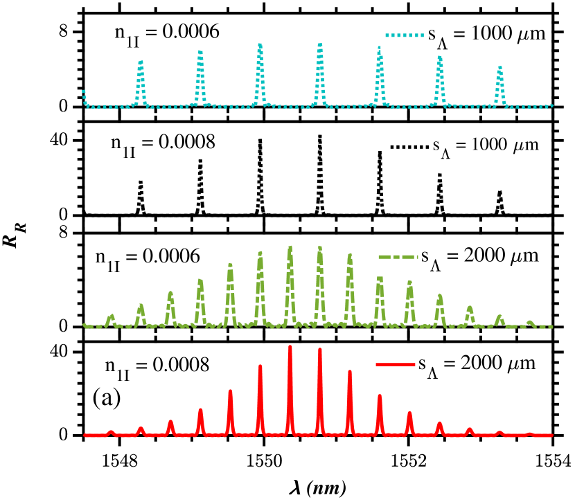
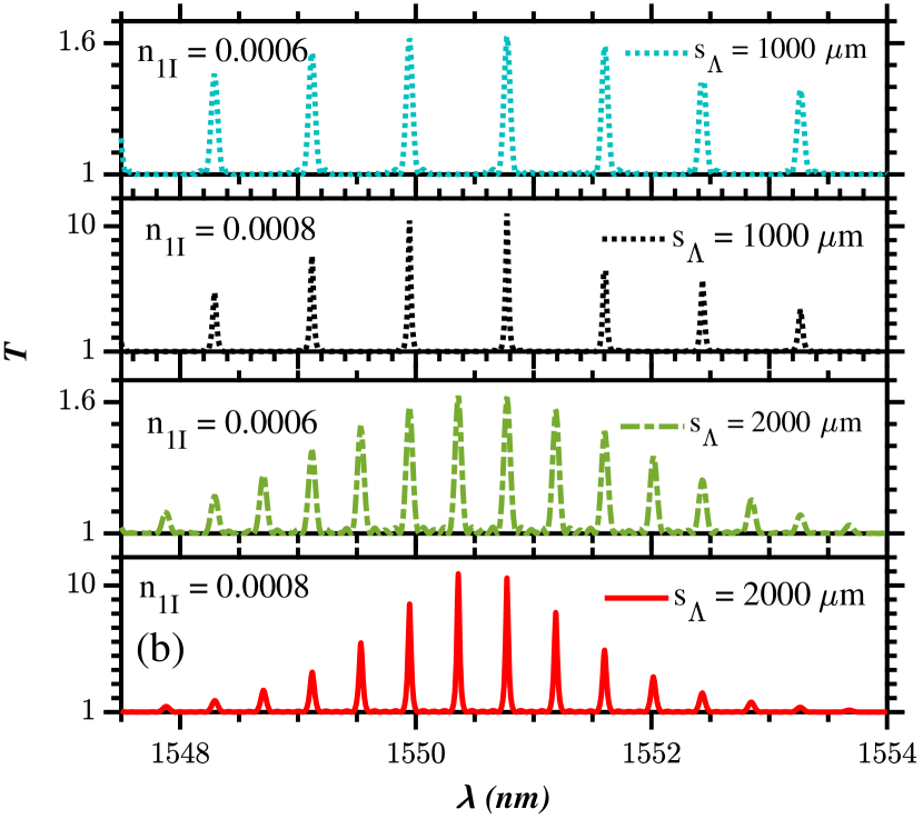
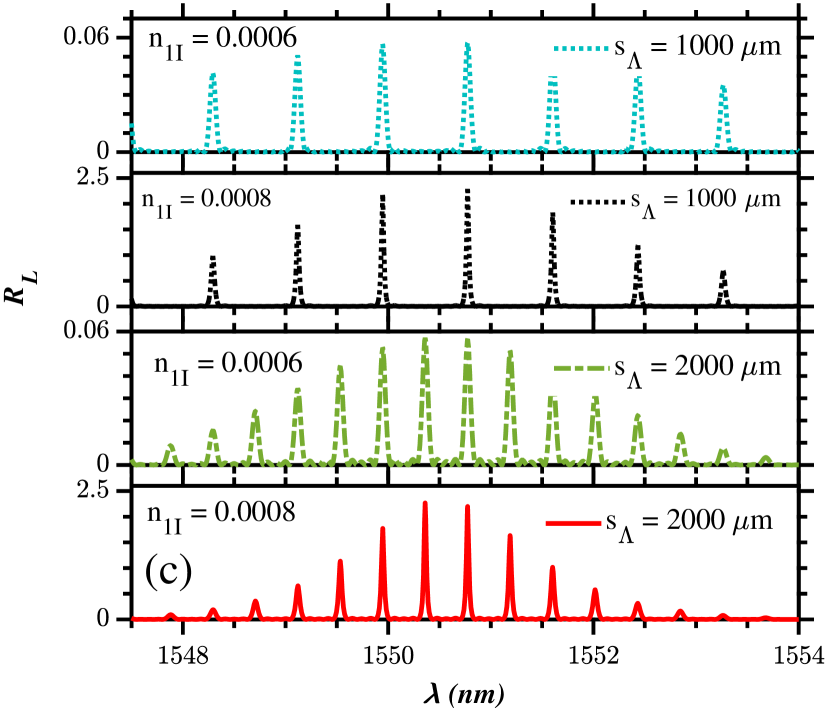
The sampling period () is a crucial parameter in the construction of sampled PTFBG structure, since it dictates the number of usable channels within the available spectral span. Also, the channel spacing between any two adjacent channels is controlled by the sampling period. Among the two spectra shown in Fig. 5(a), the first one [ = 1000 m (green and solid lines)] is characterized by less number of channels and thus features more inter channel separation width than the second one [ = 2000 m (red and dotted lines)]. Also, this is true for the reflection spectrum for left incidence as shown in Fig. 5(c). By the inherent property of the sampled FBG and the nature of sample (uniform), all these channels are equally spaced in the spatial domain as shown in Fig. 5(e). From these figures, it can be concluded that the number of channels is directly proportional to the sampling period (), whereas the channel separation is inversely proportional to and it satisfies the relation Lee2003 ; Li2003 ; Li2008 ; jayaraman1993theory ,
| (30) |
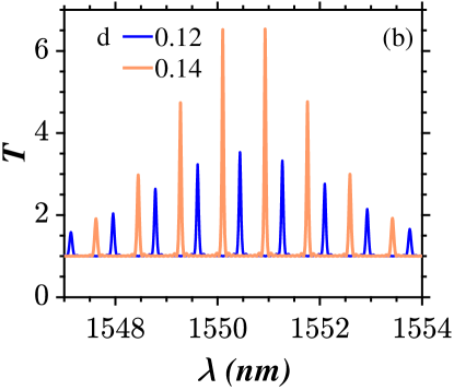
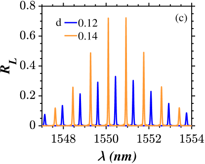
From Eq. (30), it is very obvious that designing a SFBG with larger will result in a minimal channel separation width and thereby leading to a increased number of channels within the desired spectral range. But, it should be recalled that the sampling period cannot be arbitrarily large in the perspective of conventional FBGs Navruz2008 ; Li2003 ; Li2008 as it leads to a decrease in the reflectivity of the channels away from the Bragg wavelength as shown in Fig. 5(d). Increasing the index of the core () may appear as a good choice to compensate this reduction in reflectivity from Eq. (30) but it suffers from fabrication difficulties. Instead, SFBGs with gain and loss can be employed to increase the reflectivity as shown in Fig. 5(a) as long as the input field is launched from the rear end of the device which is a unique outcome of the -symmetry. It is important to point out that the gain and loss parameters amplify the reflectivity pertaining to all the individual wavelengths of the comb spectrum (rather than equalizing the reflectivity of all channels to that of the zeroth order) so that even the channels on the edges of the designed filter will have reflectivity larger than unity as shown in Fig. 5(a). In opto-electronic approach, Erbium doped fiber amplifiers (EDFA) are used as signal boosters and they do perform the same functionality. Yet, fewer modes corresponding to = 2000 m [Fig. 5(a)] still have weak reflectivity on both sides which means that the parameter must be increased accordingly for larger sampling periods.
III.3 Impact of device length () on uniformity of combs
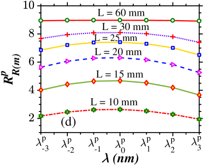
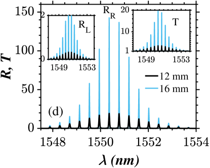
It can be inferred from Figs. 6(a) – 6(c) that the reflectivity and transmittivity of all the individual channels in the selected spectral span can be made almost uniform by increasing the physical length of the device (). This behavior is observed to be true for all the values of the sampling period. Also, the reflectivity of each channel is dramatically increased with an increase in the physical length of the device () for both left and right light incidences. As a special case, the flattening of the envelope of the spectrum for right incidence is shown in Fig. 6(d) which confirms that the systems with longer physical lengths are optimal for generation of spectrum with uniform reflectivity peaks which is a highly desired feature in the perspective of PTSFBG spectra.
III.4 Variations in the duty cycle ()
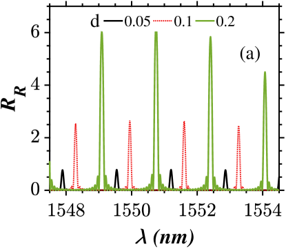
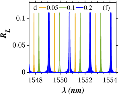
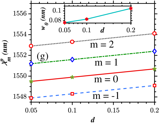
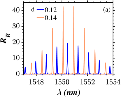
To enable an understanding about the role of duty cycle on the resulting PTSFBG spectra, the sampling period is kept at m. The duty cycle is varied between 0.05 to 0.2 for two different lengths of the grating given by and mm in the left and right panels of Fig. 7, respectively. From these figures and Eq. (2), it is very clear that if the length of the sample () is increased at a fixed value of sampling period (), it gives rise to an increase in FWHM of the individual channels as shown in Fig. 7(a) and inset of Fig. 7(e). Furthermore, it causes a shift in the spectrum towards longer wavelength sides irrespective of the sampling period and length of the device as shown in Fig. 7(g). Also, an increase in the duty cycle leads to an increase in the magnitude of reflectivity for both left and right incidences besides growth in the dip of the transmittivity for lower values of length of the device ( mm) as depicted in Figs. 7(a), 7(c) and 7(e). Hence, it is proven that the reduction in reflectivity with a number of channels can be judiciously controlled (at lower lengths) in multiple ways, via variations in gain and loss, proper choice of duty cycle, and the device length. However, for larger values of physical length of the device such as mm, it helps only in shifting the center wavelength of the spectrum and increasing the full width half maximum () as shown in Figs. 7(b), 7(d) and 7(f).
III.5 Influence of modulation strength () on FWHM
Finally, the role of the coupling parameter () on the PTSFBG spectrum is illustrated in Fig. 8. The shape of the stopband of individual channels and the corresponding FWHM are influenced by different values of the real part of the modulation strength (). If the individual channels need to posses a flat stopband and broader width, one can opt for larger modulation strengths as shown in the inset of Fig. 8(a). On the other hand, the stopband is tapered at weaker modulation strengths as shown in Figs. 8(a) and 8(b). As depicted by Fig. 8(a), the decrease in is not a major issue here, since there are other degrees of freedom offered by the PTSFBG to compensate for such a reduction in the reflectivity. Nevertheless, the reflectivity of spectrum for left incidence increases with any increase in as shown in the inset of Fig. 8(b).
III.6 Application: Tunable RF traversal filter
An optical field from a tunable broadband laser source can be directed as the input to the PTSFBG via an optical ciruclator (OCI). The resulting comb spectrum is modulated by an electro optic modulator (EOM) leng2004optimization . To impose the desired tap weights, the intensity of each channel can be judiciously controlled with the aid of programmable wave shaping devices xu2019advanced ; davies1984fibre ; mora2003tunable ; mora2002automatic . The RF input to the EOM is nothing but the message signal which is modulated on a desired carrier frequency and must be introduced alongside the optical combs xu2019advanced ; davies1984fibre . The EOM generates replicas of RF inputs to optical outputs pastor2001broad . The resulting optical signal is then passed into a single mode fiber (SMF) spool of length 23 or 50 km pastor2001broad ; leng2004optimization . The SMF offers linear dispersion characteristics to the input signals and as a result each modulated comb channel is provided with a precise time delay (). The magnitude of the delay is determined by the product of wavelength separation () between individual channels of the comb spectrum and the dispersion () offered by the SMF leng2004optimization . In the end, the delayed and weighted optical taps are mixed at the receiver (photo diode and a optical filter) pastor2001broad ; xu2019advanced . The resulting RF output signal can then be sent to a vector network analyzer (VNA). The VNA assists in recording and analyzing the RF response of the different frequency channels xu2019advanced ; leng2004optimization . This kind of RF traversal filters are potential candidates to realize any given RF transfer function with ease by tuning the appropriate tap weights mora2003tunable .
IV Unitary transmission point dynamics
At this juncture, it is essential to recollect that any type of -symmetric FBG device functioning at the unitary transmission point () will demonstrate ideal light transmission ( and ), if the light is launched from the front end (left) of the device huang2014type ; raja2020tailoring ; raja2020phase ; lin2011unidirectional ; kulishov2005nonreciprocal . From Fig. 10(a), we confirm that reflection-less light transport is exhibited by the PTSFBG irrespective of the variations in the sampling length (), sampling period (), duty cycle () or the length of the device (). However, any increase in the sampling period () increases the number of channels and vice-versa for the right light incidence as shown in Fig. 10(b). Moreover, any increase in the duty cycle () increases the reflectivity () of the channels closer to nm and marginally shifts the individual peaks as shown in Fig. 10(c). In contrast to Fig. 10(b), the reflectivity of each channel is dramatically increased in Fig. 10(d) when the length of the device is increased to mm. It should be mentioned that these behaviors can be explored in the creation of comb filters.
V Broken -symmetric regime
Any PTFBG will exhibit lasing behavior in its spectrum under the operating conditions, . Under this condition, sharp variations (exponential increase or decrease) in the reflectivity and transmittivity of the grating spectrum occur with variation in the value of . Also, the FWHM of the spectra in the broken regime is too narrow compared to the unbroken regime and thus a large amount of reflected (transmitted) power is concentrated in a narrow spectral span. For these reasons, the dynamics of the system in the broken regime is known as lasing behavior. With this note, we directly present the results pertaining to the lasing behavior exhibited by a PTSFBG in its spectrum (comb). Throughout this section, the modulation strength parameter and length are kept constant as and mm, respectively (unless specified).
V.1 Impact of on the lasing spectra
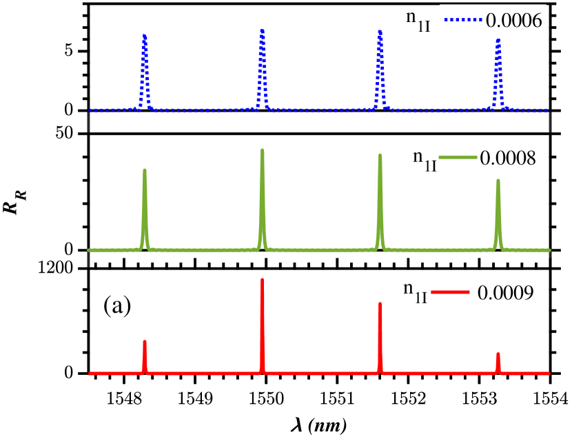
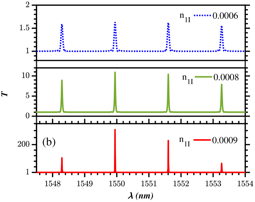
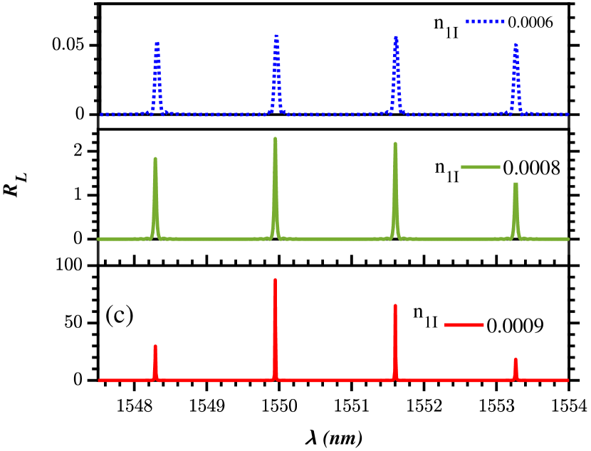
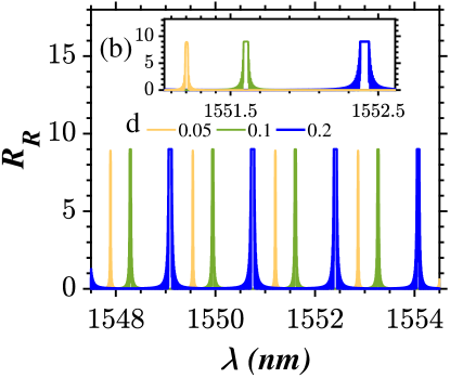
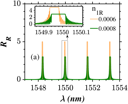
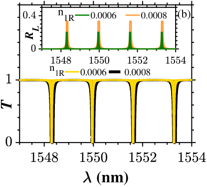
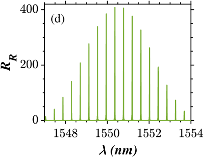
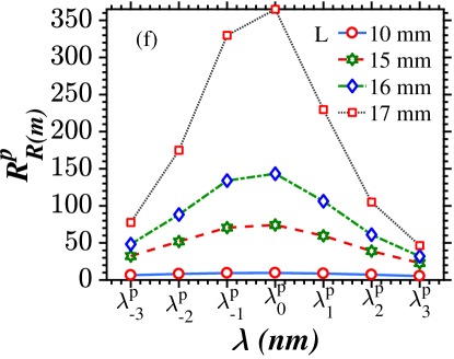
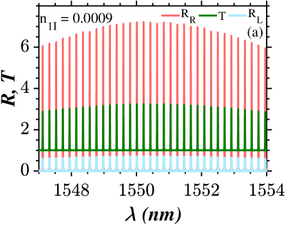
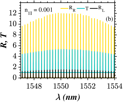
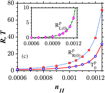
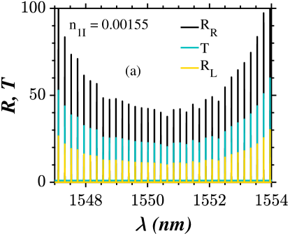
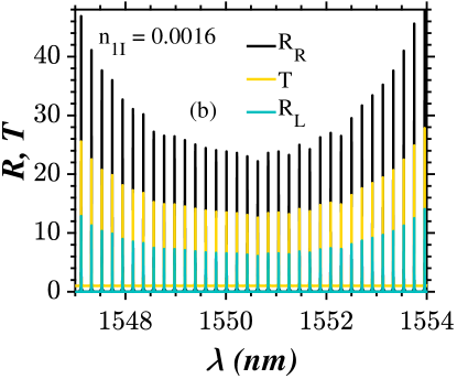
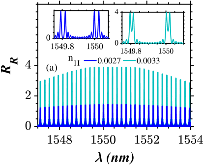
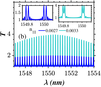
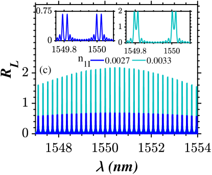
Figures 11(a) – 11(c) depict the formation of lasing combs with fewer modes. From these figures, it is very clear that the value of gain and loss affects the lasing spectrum by two means: Primarily, with an increase in the value of , the reflectivity and transmittivity of each mode get intensified. Secondly, the FWHM of the individual wavelengths of lasing spectrum gets reduced with the increase of . The mode which is closer to the Bragg wavelength (zeroth order) receives maximum amplification. On either side of the zeroth order mode, the first order lasing modes of the spectrum appear. As the order of the mode increases, both reflectivity ( and ) and transmittivity () get decreased. The lasing modes at the edges of the spectrum (scaled to to nm here) feature lesser amplification and so the peaks corresponding to individual modes are non-identical in magnitude. Nevertheless, each mode is equally spaced () in a given wavelength range.
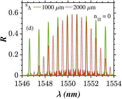
V.2 Role of sampling period () on the number of the modes
In Fig. 11, the number of channels within the available range is few (four). If additional modes are desired in the lasing spectra, the obvious choice is to increase the sampling period as shown in Fig. 12. This also results in a decrease in the wavelength separation () between the adjacent modes of the spectra. For instance, seven channels are visible in the output spectrum for a sampling period of = m. As mentioned earlier, the reflectivity (transmittivity) of the modes far away from the Bragg wavelength is not as much as that of the zeroth order modes as depicted in Figs. 12(a) – 12(c).
V.3 Variation in the duty cycle ()
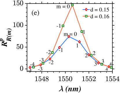
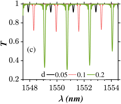
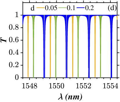
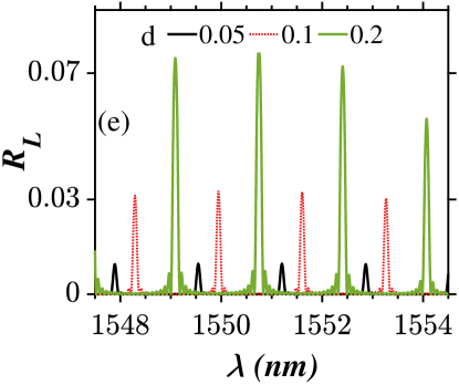
The duty cycle parameter offers two important functionalities over the control of the PTSFBG lasing spectra, namely the magnitude control and location of the spectrum on the wavelength axis. As gets larger, the comb lasing spectrum shows growth in reflectivity as well as in transmittivity. Also, the combs are shifted towards longer wavelengths as shown in Figs. 13(a) – 13(c). Under duty cycle variations, the nonuniformity in the magnitude of the comb exists which is mainly due to the extreme amplification of the zeroth order mode as shown in Fig. 13(e). The degree of dissimilarity among the reflectivity of these spectral modes further builds up with any increase in the length of the structure as shown in Figs. 13(d) and 13(f).
V.4 Comb lasing spectrum with uniform and
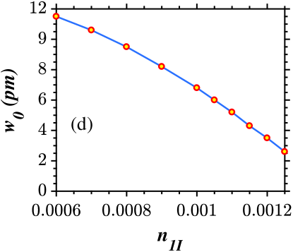
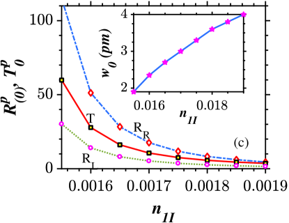
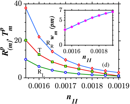
Unlike the unbroken -symmetric regime, increasing the length of the overall structure itself cannot make the lasing spectrum uniform (nearly) as shown in Fig. 13(f) because of the constrain that extreme amplification of the zeroth order mode in the broken regime strongly depends on the sampling length. In other words, the inherent nature of the sample to favor stronger amplification of a particular mode must be cut down. Without managing this effect, the choice of longer device length will further build up the unevenness among the reflectivity of the individual channels. From a theoretical perspective, different duty cycle values were tested and a value of is found to be optimum for generation of comb lasing spectrum with nearly uniform reflectivity and transmittivity at a device length of mm. It is noteworthy to mention that such a decrement in the duty cycle is not feasible in the context of conventional SFBG structures due to the fact that reduction in the duty cycle adversely decreases the reflectivity of the device. The role of the sampling period is very much the same as illustrated previously in Fig. 12 except that the channels are nearly uniform in amplitude in all the cases. In other words, if increases at a fixed value of sampling length (), the system can accommodate more channels with a reduced inter channel separation and vice-versa. The variation in gain and loss brings an increase in and as shown in Figs. 14(a), 14(b) and 14(c). Also, the FWHM () decreases with an increase in as seen in Fig. 14(d). This confirms that the magnitude of the reflection spectrum is inversely proportional to the FWHM of the modes. However, larger values of brings about nonuniformity in the values of reflectivity and transmittivity.
V.5 Comb lasing spectrum with an inverted envelope
Another distinct attribute of the gain and loss parameter is that it gives rise to a comb lasing spectrum with an uncommon envelope shape as shown in Figs. 15(a) – 15(b). Explicitly, the system facilitates larger amplifications for the order modes appearing at the edges of the given wavelength span. For the subsequent order modes, the reflectivity and transmittivity are lesser than the previously occurring modes and along these lines, the zeroth order modes exhibit lowest amplification as shown in Figs. 15(c) and 15(d). This is the exact counterpart of the lasing spectrum discussed in the first three subsections of the broken -symmetric regime which is characterized by an intense amplification at the center (zeroth order) and lowest amplification at the edges ( order). As the value of is increased between the range and , this behavior in the lasing spectrum is observed in a fashion that the stronger amplification at the higher order modes is inhibited progressively with an increase in . But the overall shape of the inverted envelope is maintained throughout this range of gain and loss.
V.6 Comb lasing spectrum with dual mode lasing channels
When , we observe the usual lasing spectrum with a conventional envelope shape except that each individual channel demonstrates a dual mode lasing behavior. A dip is visible in between two peaks of the individual modes as shown in Figs. 16(a) – 16(c). This dip exactly occurs at and (or closer to those values) when is less. As the value of the imaginary part of the modulation strength is gradually increased, and values of individual modes are also enhanced whereas the depth of penetration of this dip drops off and finally the dip vanishes for . Beyond this, again comb spectrum with single mode lasing channels appears.
V.7 Application of PTSFBG in the broken -symmetric regime: Tunable Laser
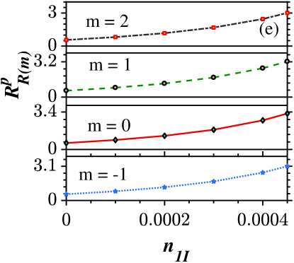
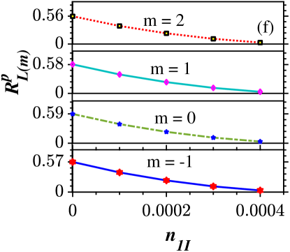
From Fig. 14, we infer that it possible to generate uniformly spaced lasing modes with uniform intensities and narrow FWHM with the aid of the proposed system. Since each mode in the output spectrum represents a distinct wavelength and the separation between these modes is very narrow, the device can be effectively used as tunable multi-wavelength laser source which can simultaneously be fed as inputs for multiple transmitters. To construct such a tunable laser source, two PTSFBGs with a gain element should be engineered. It should be noted that wavelength tuning of the -symmetric tunable laser (PTTL) requires the two PTSFBGs to have different sampling periods jayaraman1993theory ; bidaux2015extended . The tuning is based on the principle of Vernier effect (in the reflection spectra) which occurs as a consequence of variation in the channel spacing of two dissimilar SFBGs (having different sampling periods) xu2005chirped ; bidaux2015extended . Vernier effect states that when one of these superstructured gratings is tuned, constructive interference occurs between the pair of modes which are common to both the gratings, thereby leading to lasing at these wavelengths and suppression of the other lasing modes whose center wavelength does not coincide. For instance, consider two PTSFBGs having different sampling periods and 2000 m. From Fig. 4(e), we infer that nm is one among the center wavelengths which is common to both the resulting comb spectra ( and 2000 m), whereas nm is not so. The resulting spectra from the PTTL will feature a comb mode at nm and its reflectivity will be the product of reflectivities of the individual PTSFBGs. In a similar fashion, other overlapping modes are selected and amplified by the PTTL. On the other hand, the lasing at the non-overlapping wavelengths are totally suppressed, for instance nm.
It is desirable to acquire replicas of laser output fields with the same intensities for all the channels xu2005chirped . Therefore, PTSFBGS exhibiting uniform reflectivity across all the wavelengths (in the given range) must be employed. To flatten the envelope of the output spectra, many SFBG structures were investigated in the literature, including chirped SFBGs Dong2006 , and sinc sampled FBGs Loh1999 . In the chirped SFBGs, either the grating period or sampling length or sampling period or combinations of the above can be chirped Lee2003 ; Dong2006 ; Lee2004 ; Lee2004a ; Loh1999 ; azana2005spectral . But, the resolution of the spectrum strongly depends on the lithographic process used for fabrication of these gratings bidaux2015extended . Alternatively, phase shifted SFBGS were proposed in which optimization of the number of phase shift regions required is tedious Lee2003 ; Li2008 ; Navruz2008 ; Shi2018 ; Zhang2019 .
Here, we demonstrate that it is possible to generate the same lasing spectrum (with nearly uniform reflectivity) with -symmetric uniform grating samples. The envelope formed by reflectivity peaks of different channels widens with larger duty cycle values in conventional SFBGS hansmann1995variation . Reducing the duty cycle to smaller values is also not an ideal way in the perspective of conventional SFBGS as it adversely decreases the reflectivity jayaraman1993theory ; Lee2003 . One could visualize from Figs. 14 and 16 that PTSFBGs have two important features: First, the output spectrum features enhanced reflectivity. Second, the envelope is much flatter as a result of smaller duty cycle values (for example, ). Achieving these two features simultaneously is an exceptional feature of PTSFBG, thanks to the concepts of gain and loss. It should be recalled that these structures can be fabricated using an Argon laser with the standard scan-writing technology xu2019advanced . The modern translation stages which hold the phase mask exhibit an infinitely small moving precision of the order of 5 nm xu2005chirped and above and thus fabricating a small length of sample should not be a tough task to our knowledge. We also visualize that much of the PTSFBG structure is unused as a result of the larger sampling period at very low duty cycles. These unused regions can be used to fabricate interleaved samples having different Bragg wavelengths Loh1999 ; Lee2004a . The period () of each interleaved PTFBG should be different. Otherwise, the comb spectrum from two different PTSFBGs may impose on one another. In simpler words, the concept of interleaving refers to the fabrication of several PTSFBGs on the same fiber with different periods () in such a way that the physical concept leads to interleaving effect on the spectrum as well Loh1999 . As theoretical physicists, we believe some of the challenges remains now for the experimental realization of these -symmetric devices are to find a suitable dopant material like Er3+ and Cr3+ for the fabrication of the PTSFBG with gain and loss regions, respectively ozdemir2019parity . Even though it looks very simple to achieve phase transitions such as unitary transmission point and broken symmetry in -symmetric systems by simply tuning the value of , certain practical challenges still remain to be addressed by the experimental physicist. One can think of tuning the value of permittivity of both the gain medium as well as the lossy medium, simultaneously by the help of external pumping source. Another way for achieving these types of phase transitions is by varying the frequency of the incident optical field, appropriately. This may lead to the violation of causality principle and -symmetric operation is bound to occur only at isolated frequencies and not on a continuous interval of frequencies Ge2012 . This type of violation occurs as a result of Kramers-Kronig relations which describe the fact that the variation in the imaginary part of the index can also lead to a change in its real part Zyablovsky2014 . Nevertheless, it is to be noted that a continuous tuning of gain and loss through pumping is still feasible at the resonant frequency Nguyen2016 . In such a case, it should be remembered that the amount of pumping should be lesser in the lossy regions and higher in the gain regions to achieve -symmetry Phang2018 ; Phang2015res . As theoretical physicists, we expect the experimentalists to put forward suitable strategies to address these challenges to make -symmetric combs more realistic.
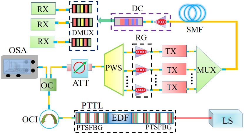
Having briefly discussed on the principle of operation, existing structures, experimental feasibility and the advantages of the proposed scheme, we look at the operation of the experimental set up illustrated by Fig. 17. The input optical signal to the PTTL can be pumped from a CW laser. It can be directly fed to the PTTL with an OCI as shown in the schematic or the input signal may be amplified with a EDFA and be passed through a uniform FBG to filter out the EDFA noise chembo2016kerr . The PTTL can be constructed with two PTSFBGs with comb like reflection spectrum as discussed above. The EDF in the optical cavity serves as the gain medium alongside the tuning PTSFBGs and this generates a laser source over its gain profile jayaraman1993theory ; xu2005chirped ; othonos2006fibre ; kryukov2019laser . When one of the non identical PTSFBGs is tuned, lasing will take place at a particular channel, if and only if the comb lines from both the PTSFBGs intersect. In other words, reflectivity multiplies at the overlapping channels and the lasing at the other wavelengths is inhibited xu2005chirped ; bidaux2015extended ; schneider2005sampled ; jayaraman1993theory . Thus, it is possible to obtain multiwavelength comb lasers with nearly identical intensities with controlled precision and the same can be visualized via an OSA schneider2005sampled ; xu2005chirped . The variable optical attenuator is used to flatten the envelope of the comb laser further. In the case of comb lasers with extreme amplification at the center wavelength, these attenuators can be followed by a notch filter which is helpful in attenuating the power levels of these modes to comparable levels chembo2016kerr .
The programmable wave shapers separate the comb lines in wavelength which serve as carrier signals xu2019advanced . Also, it is useful to separate the interleaved channels chembo2016kerr . These carriers are regenerated by the EDFA before they are fed to the transmitters. In the transmitter side, multiple laser sources are required to drive each transmitter which makes the system bulky bidaux2015extended . PTSFBG are fascinating in a sense that they serve as the alternative solution to build a compact and reconfigurable transmitter system, since they serve as the building block to fabricate a broadband laser source which is then separated in terms of wavelengths by the PWS according to the number of transmitters kryukov2019laser . The new generation transmitters come with inbuilt phase modulators and the stream of data from all these transmitters are multiplexed and sent to the transport fiber chembo2016kerr . SMFs are generally used as long distance transport fibers. As the signal travels in the fiber, attenuation and broadening mechanism comes into the picture and to compensate these detrimental effects, EDFA and a chirped PTFBG, respectively, can be used in the compensation module. The advantages of chirped PTFBG is that they can compensate both normal and anamolous dispersions simply by the concept of reversal of direction of incidence raja2020tailoring . We also reported the construction of demultiplexers with -symmetric phase shifted FBGs, in our previous work which can demultiplex all the data streams from the multiplexed input signal raja2020phase . At the receivers, all these signals are demodulated and coherently detected chembo2016kerr .
VI Conclusions
In this article, we have presented a complete description of the comb spectrum of a PTSFBG with uniform sampling. We first illustrated the role of various device parameters, namely the sampling period, duty cycle and gain-loss parameter on the generation of the comb spectrum in the three different -symmetric regimes, namely the unbroken, Unitary transmission point and broken symmetric regimes. Special emphasis was given to the generation of uniform amplitude comb filters with narrow channel spacing in the unbroken regime. The major highlight of this section is that it provides a framework towards the generation of a large number channels with significantly large reflectivity by increasing the sampling period of the grating. It also confirms that the decrease in the reflectivity (with increasing number of channels) can be independently controlled with the aid of gain and loss parameter. An architecture which can possibly serve as a tunable RF traversal filter was proposed at the end of Sec. III. We then presented a brief analysis on the dependence of comb spectrum on the different control parameters for the case of right light incidence at the unitary transmission point. Remarkably, the reflectionless wave transport phenomenon was observed under similar conditions when the direction of light incidence is reversed. This once again proves that the concept of unidirectional wave transport is a distinct feature of any PTFBG system and is unresponsive to any variation in other device parameters except for evenly balanced values of real and imaginary parts of the modulation strength.
Further, the analysis required for figuring out the interdependence between the changes in the lasing spectrum against the variation in the grating parameters in the case of broken -symmetric regime is discussed in Sec. V. We then proposed an optimal way to generate comb lasing spectrum with uniform reflectivity across different wavelengths by decreasing the duty cycle of the grating. Such a reduction in the duty cycle is not feasible in the context of conventional PTSFBGs due to the dependence of reflectivity on the duty cycle and coupling coefficient. It was proved that it is possible to obtain comb spectrum flattened envelope as well as uniform reflectivity for different wavelengths as a result of the interplay between the reduced duty cycle and large gain-loss parameter. Surprisingly, the tuning of gain and loss parameter also leads to the generation of lasing spectrum with an unconventional inverted envelope and dual mode lasing behavior in the individual channels. Towards the end, we showed that a single laser source from a PTSFBG can drive multiple transmitters in a wavelength division multiplexing network. The architecture also integrates different modules like dispersion compensator and demultiplexer based on PTFBGs. The physical behavior exploited for the comb application is reported only from the perspective of FBGs without gain and loss. This is the very first time, to the best of our knowledge, these applications have been dealt from the viewpoint of -symmetric superstructures. From a fundamental perspective, gain and loss provides an additional degree of freedom to control the intensity and FWHM of the comb spectra. From the application perspective, the inclusion of gain and loss in the form of -symmetry opens up an alternative route to overcome some of the critical problems like regrowth challenges prevailing in the current hybrid integration optical technologies to build tunable and reconfigurable devices. With advancements in lightwave technology, these PTFBG based devices are expected to be available in the near future, credits to their improved spectral features and the number of degrees of freedom to manipulate them.
Acknowledgments
SVR is indebted to a financial assistantship provided by Anna University through an Anna Centenary Research Fellowship (CFR/ACRF-2018/AR1/24). AG and ML acknowledge the support by DST-SERB for providing a Distinguished Fellowship (Grant No. SB/DF/04/2017) to ML in which AG was a Visiting Scientist. AG is now supported by the University Grants Commission (UGC), Government of India, through a Dr. D. S. Kothari Postdoctoral Fellowship (Grant No. F.4-2/2006 (BSR)/PH/19-20/0025).
References
- (1) L. Pilozzi and C. Conti, Topological cascade laser for frequency comb generation in -symmetric structures, Opt. Lett. 42, 5174 (2017).
- (2) D. J. Jones, S. A. Diddams, J. K. Ranka, A. Stentz, R. S. Windeler, J. L. Hall, and S. T. Cundiff, Carrier-envelope phase control of femtosecond mode-locked lasers and direct optical frequency synthesis, Science 288, 635 (2000).
- (3) T. Fortier and E. Baumann, 20 years of developments in optical frequency comb technology and applications, Commun. Phys. 2, 1 (2019).
- (4) J. Jin, Y.-J. Kim, Y. Kim, S.-W. Kim, and C.-S. Kang, Absolute length calibration of gauge blocks using optical comb of a femtosecond pulse laser, Opt. Express 14, 5968 (2006).
- (5) P. Del’Haye, A. Schliesser, O. Arcizet, T. Wilken, R. Holzwarth, and T. J. Kippenberg, Optical frequency comb generation from a monolithic microresonator, Nature 450, 1214 (2007).
- (6) T. Herr, V. Brasch, J. D. Jost, C. Y. Wang, N. M. Kondratiev, M. L. Gorodetsky, and T. J. Kippenberg, Temporal solitons in optical microresonators, Nat. Photonics 8, 145 (2014).
- (7) X. Dong, P. Shum, X. Yang, M. F. Lim, and C. C. Chan, Bandwidth-tunable filter and spacing-tunable comb filter with chirped-fiber Bragg gratings, Opt. Commun. 259, 645 (2006).
- (8) H. Lee and G. P. Agrawal, Purely phase-sampled fiber Bragg gratings for broad-band dispersion and dispersion slope compensation, IEEE Photonics Technol. Lett. 15, 1091 (2003).
- (9) H. Lee and G. P. Agrawal, Bandwidth equalization of purely phase-sampled fiber Bragg gratings for broadband dispersion and dispersion slope compensation, Opt. Express 12, 5595 (2004).
- (10) H. Lee and G. P. Agrawal, Add-Drop Multiplexers and Interleavers With Broad-Band Chromatic Dispersion Compensation Based on Purely Phase-Sampled Fiber Gratings, IEEE Photonics Technol. Lett. 16, 635 (2004).
- (11) H. Li, Y. Sheng, Y. Li, and J. E. Rothenberg, Phase-Only Sampled Fiber Bragg Gratings for High-Channel-Count Chromatic Dispersion Compensation, J. Light. Technol. 21, 2074 (2003).
- (12) W. H. Loh, F. Q. Zhou, and J. J. Pan, Sampled fiber grating based-dispersion slope compensator, IEEE Photonics Technol. Lett. 11, 1280 (1999).
- (13) I. Navruz and N. F. Guler, A novel technique for optical dense comb filters using sampled fiber Bragg gratings, Opt. Fiber Technol. 14, 114 (2008).
- (14) L. Zhang, F. Yan, W. Han, Y. Bai, Z. Bai, D. Cheng, H. Zhou, Y. Suo, and T. Feng, Transmission characteristics of sampled fiber Bragg grating and phase-shifted sampled fiber Bragg grating in the 2m band, Opt. Fiber Technol. 50, 263 (2019).
- (15) X. H. Zou, W. Pan, B. Luo, Z. M. Qin, M. Y. Wang, and W. L. Zhang, Periodically chirped sampled fiber Bragg gratings for multichannel comb filters, IEEE Photonics Technol. Lett. 18, 1371 (2006).
- (16) C. Gohle, T. Udem, M. Herrmann, J. Rauschenberger, R. Holzwarth, H. A. Schuessler, F. Krausz, and T. W. Hänsen, A frequency comb in the extreme ultraviolet, Nature 436, 234 (2005).
- (17) A. Baltuška, T. Udem, M. Uiberacker, M. Hentschel, E. Goulielmakis, C. Gohle, R. Holzwarth, V. Yakovlev, A. Scrinzi, T. W. Hänsch et al., Attosecond control of electronic processes by intense light fields, Nature 421, 611 (2003).
- (18) O. Pfister, Continuous-variable quantum computing in the quantum optical frequency comb, J. Phys. B At. Mol. Opt. Phys. 53 (2020).
- (19) T. Udem, R. Holzwarth, and T. W. Hänsch, Optical frequency metrology, Nature 416, 233 (2002).
- (20) V. Jayaraman, Z.-M. Chuang, and L. A. Coldren, Theory, design, and performance of extended tuning range semiconductor lasers with sampled gratings, IEEE J. Quantum Electron. 29, 1824 (1993).
- (21) R. Holzwarth, T. Udem, T. W. Hänsch, J. Knight, W. Wadsworth, and P. S. J. Russell, Optical frequency synthesizer for precision spectroscopy, Phys. Rev. Lett. 85, 2264 (2000).
- (22) J. L. Hall, Nobel lecture: Defining and measuring optical frequencies, Rev. Mod. Phys. 78, 1279 (2006).
- (23) T. W. Hänsch, Nobel lecture: passion for precision, Rev. Mod. Phys. 78, 1297 (2006).
- (24) H. Ishii, Y. Tohmori, Y. Yoshikuni, T. Tamamura, and Y. Kondo, Multiple-phase shift super structure grating DBR lasers for broad wavelength tuning, IEEE Photon. Technol. Lett. 5, 613 (1993).
- (25) Y. Sourani, A. Bekker, B. Levit, and B. Fischer, Tuning, selecting and switching wavelengths in lasers with chirped and sampled fiber Bragg gratings by high-order mode-locking, Opt. Commun. 431, 151 (2019).
- (26) X. Shu, K. Chisholm, I. Felmeri, K. Sugden, A. Gillooly, L. Zhang, and I. Bennion, Highly sensitive transverse load sensing with reversible sampled fiber Bragg gratings, Appl. Phys. Lett. 83, 3003 (2003).
- (27) M. Li, H. Li, and Y. Painchaud, Multi-channel notch filter based on a phase-shift phase-only sampled fiber Bragg grating, Opt. Express 16, 19388 (2008).
- (28) B. J. Eggleton, P. A. Krug, L. Poladian, and F. Ouellette, Long periodic superstructure Bragg gratings in optical fibres, Electron. Lett. 30, 1620 (1994).
- (29) C. M. De Sterke, B. J. Eggleton, and P. A. Krug, High-intensity pulse propagation in uniform gratings and grating superstructures, J. Light. Technol. 15, 1494 (1997).
- (30) B. J. Eggleton, R. E. Slusher, and C. M. de Sterke, Nonlinear propagation in superstructure Bragg gratings, Opt. Lett. 21, 1223 (1996).
- (31) C. M. de Sterke, D. G. Salinas, and J. E. Sipe, Coupled-mode theory for light propagation through deep nonlinear gratings, Phys. Rev. E 54, 1969 (1996).
- (32) C. M. de Sterke and N. G. R. Broderick, Coupled-mode equations for periodic superstructure Bragg gratings, Opt. Lett. 20, 2039 (1995).
- (33) T. Erdogan, Fiber grating spectra, J. Light. Technol. 15, 1277 (1997).
- (34) M. Ibsen, M. K. Durkin, M. J. Cole, and R. I. Laming, Sinc-sampled fiber Bragg gratings for identical multiple wavelength operation, IEEE Photon. Technol. Lett. 10, 842 (1998).
- (35) T. Kottos, Optical physics: Broken symmetry makes light work, Nat. Phys. 6, 166 (2010).
- (36) R. El-Ganainy, K. Makris, D. Christodoulides, and Z. H. Musslimani, Theory of coupled optical -symmetric structures, Opt. Lett. 32, 2632 (2007).
- (37) C. E. Rüter, K. G. Makris, R. El-Ganainy, D. N. Christodoulides, M. Segev, and D. Kip, Observation of parity–time symmetry in optics, Nat. phys. 6, 192 (2010).
- (38) A. K. Sarma, Modulation instability in nonlinear complex parity-time symmetric periodic structures, J. Opt. Soc. Am. B 31, 1861 (2014).
- (39) Z. Lin, H. Ramezani, T. Eichelkraut, T. Kottos, H. Cao, and D. N. Christodoulides, Unidirectional invisibility induced by -symmetric periodic structures, Phys. Rev. Lett. 106, 213901 (2011).
- (40) S. Phang, A. Vukovic, H. Susanto, T. M. Benson, and P. Sewell, Ultrafast optical switching using parity–time symmetric Bragg gratings, J. Opt. Soc. Am. B 30, 2984 (2013).
- (41) M.-A. Miri, A. B. Aceves, T. Kottos, V. Kovanis, and D. N. Christodoulides, Bragg solitons in nonlinear -symmetric periodic potentials, Phys. Rev. A 86, 033801 (2012).
- (42) C. Huang, R. Zhang, J. Han, J. Zheng, and J. Xu, Type-II perfect absorption and amplification modes with controllable bandwidth in combined -symmetric and conventional Bragg-grating structures, Phys. Rev. A 89, 023842 (2014).
- (43) A. Govindarajan, A. K. Sarma, and M. Lakshmanan, Tailoring -symmetric soliton switch, Opt. Lett. 44, 663 (2019).
- (44) M. Kulishov, J. M. Laniel, N. Bélanger, J. Azaña, and D. V. Plant, Nonreciprocal waveguide Bragg gratings, Opt. Express. 13, 3068 (2005).
- (45) A. T. Lupu, H. Benisty, and A. V. Lavrinenko, Tailoring spectral properties of binary -symmetric gratings by duty-cycle methods, IEEE J. Sel. Top. Quantum Electron. 22, 35 (2016).
- (46) S. V. Raja, A. Govindarajan, A. Mahalingam, and M. Lakshmanan, Tailoring inhomogeneous -symmetric fiber-Bragg-grating spectra, Phys. Rev. A 101, 033814 (2020).
- (47) S. V. Raja, A. Govindarajan, A. Mahalingam, and M. Lakshmanan, Phase-shifted -symmetric periodic structures, Phys. Rev. A 102, 013515 (2020).
- (48) S. Longhi, Supersymmetric Bragg gratings, J. Opt. 17, 045803 (2015).
- (49) S. Longhi, Optical realization of relativistic non-Hermitian quantum mechanics, Phys. Rev. Lett. 105, 013903 (2010).
- (50) S. Phang, A. Vukovic, T. M. Benson, H. Susanto, and P. Sewell, A versatile all-optical parity-time signal processing device using a Bragg grating induced using positive and negative Kerr-nonlinearity, Opt. Quant. Electron. 47, 37 (2015).
- (51) S. Phang, A. Vukovic, H. Susanto, T. M. Benson, and P. Sewell, Impact of dispersive and saturable gain/loss on bistability of nonlinear parity–time Bragg gratings, Opt. Lett. 39, 2603 (2014).
- (52) S. Longhi, -symmetric laser absorber, Phys. Rev. A 82, 031801(R) (2010).
- (53) R. Kashyap, Fiber Bragg Gratings (Academic Press 2009).
- (54) X. Xu, M. Tan, J. Wu, T. G. Nguyen, S. T. Chu, B. E. Little, R. Morandotti, A. Mitchell, and D. J. Moss, Advanced adaptive photonic RF filters with 80 taps based on an integrated optical micro-comb source, J. Light. Technol. 37, 1288 (2019).
- (55) D. Pastor, J. Capmany, and B. Ortega, Broad-band tunable microwave transversal notch filter based on tunable uniform fiber Bragg gratings as slicing filters, IEEE Photonics Technol. Lett. 13, 726 (2001).
- (56) J. Leng, W. Zhang, and J. A. Williams, Optimization of superstructured fiber Bragg gratings for microwave photonic filters response, IEEE Photonics Technol. Lett. 16, 1736 (2004).
- (57) D. Davies and G. James, Fibre-optic tapped delay line filter employing coherent optical processing, Electron. Lett. 20, 95 (1984).
- (58) E. Hamidi, D. E. Leaird, and A. M. Weiner, Tunable programmable microwave photonic filters based on an optical frequency comb, IEEE Trans. Microwave Theory and Tech. 58, 3269 (2010).
- (59) J. Mora, M. Andres, J. Cruz, B. Ortega, J. Capmany, D. Pastor, and S. Sales, Tunable all-optical negative multitap microwave filters based on uniform fiber Bragg gratings, Opt. Lett. 28, 1308 (2003).
- (60) J. Mora, B. Ortega, J. Capmany, J. Cruz, M. Andres, D. Pastor, and S. Sales, Automatic tunable and reconfigurable fiber-optic microwave filters based on a broadband optical source sliced by uniform fiber Bragg gratings, Opt. Express 10, 1291 (2002).
- (61) Y. Bidaux, A. Bismuto, C. Tardy, R. Terazzi, T. Gresch, S. Blaser, A. Muller, and J. Faist, Extended and quasi-continuous tuning of quantum cascade lasers using superstructure gratings and integrated heaters, Appl. Phys. Lett. 107, 221108 (2015).
- (62) X. Xu, Y. Dai, X. Chen, D. Jiang, and S. Xie, Chirped and phase-sampled fiber Bragg grating for tunable DBR fiber laser, Opt. Express 13, 3877 (2005).
- (63) J. Azaña, C. Wang, and L. R. Chen, Spectral self-imaging phenomena in sampled Bragg gratings, J. Opt. Soc. Am. B 22, 1829 (2005).
- (64) N. Shi, T. Hao, W. Li, N. Zhu, and M. Li, A reconfigurable microwave photonic filter with flexible tunability using a multi-wavelength laser and a multi-channel phase-shifted fiber Bragg grating, Opt. Commun. 407, 27 (2018).
- (65) S. Hansmann, H. Hillmer, H. Walter, H. Burkhard, B. Hubner, and E. Kuphal, Variation of coupling coefficients by sampled gratings in complex coupled distributed-feedback lasers, IEEE J. Sel. Top. Quantum Electron. 1, 341 (1995).
- (66) Ş. Özdemir, S. Rotter, F. Nori, and L. Yang, Parity–time symmetry and exceptional points in photonics, Nat. Mater. 18, 783 (2019).
- (67) Y. K. Chembo, Kerr optical frequency combs: theory, applications and perspectives, Nanophotonics 5, 214 (2016).
- (68) A. Othonos, K. Kalli, D. Pureur, and A. Mugnier, Fibre Bragg gratings, in Wavelength Filters in Fibre Optics (Springer 2006), pp. 189–269.
- (69) P. G. Kryukov, Laser optical frequency combs and their applications in optical fibre communication systems and astrophysics, Quantum Electron. 49, 895 (2019).
- (70) L. Schneider, M. Pfeiffer, J. Piprek, A. Witzig, and B. Witzigmann, Sampled-grating DBR lasers: calibrated 3d simulation of tuning characteristics, in Opto-Ireland 2005: Optoelectronics, Photonic Devices, and Optical Networks (International Society for Optics and Photonics 2005), volume 5825, pp. 95–106.
- (71) A. A. Zyablovsky, A. P.Vinogradov, A. V.Dorofeenko, A. A. Pukhov, and A. A. Lisyansky, Causality and phase transitions in -symmetric optical systems, Phys. Rev. A, 89, 3, 033808 (2014).
- (72) S. Phang, A. Vukovic, S. C.Creagh, T. M. Benson, P. D. Sewell, and G. Gradoni, Parity-time symmetric coupled microresonators with a dispersive gain/loss, Opt. Express, 23, 9, 11493 (2015).
- (73) N. B. Nguyen, S. A. Maier, M. Hong, and R. F.Oulton, Recovering parity-time symmetry in highly dispersive coupled optical waveguides, New J. Phys, 18, 12, 125012 (2016).
- (74) S. Phang, T. M. Benson, H. Susanto, S. C. Creagh, G. Gradoni, P. D. Sewell, and A. Vukovic, Theory and Numerical Modelling of Parity-Time Symmetric Structures in Photonics: Introduction and Grating Structures in One Dimension, arXiv, arXiv-1801 (2018).
- (75) L. Ge, Y. D.Chong, and A. D.Stone, Conservation relations and anisotropic transmission resonances in one-dimensional -symmetric photonic heterostructures, Phys. Rev. A, 85, 2, 023802 (2012).