Slow-light enhanced frequency combs and dissipative Kerr solitons in silicon coupled-ring microresonators in the telecom band
Abstract
We propose a system of coupled microring resonators for the generation frequency combs and dissipative Kerr solitons in silicon at telecommunication frequencies. By taking advantage of structural slow-light, the effective non-linearity of the material is enhanced, thus relaxing the requirement of ultra-high quality factors that currently poses a major obstacle to the realization of silicon comb devices. We demonstrate a variety of frequency comb solutions characterized by threshold power in the 10-milliwatt range and a small footprint of mm2, and study their robustness to structural disorder. The results open the way to the realization of low-power compact comb devices in silicon at the telecom band.
I Introduction
Kerr frequency combs in microresonators have been the object of intense research during the last decade, due to their wide range of applications in science and engineering Chembo (2016a); Fortier and Baumann (2019); Gaeta et al. (2019); Diddams et al. (2020). They have brought about significant advances in several areas of sensing and communications, such as light detection and ranging (LIDAR) Trocha et al. (2018), optical atomic clocks Newman et al. (2019), exoplanet exploration Obrzud et al. (2019), optical frequency synthesis Spencer et al. (2018) and high-resolution spectroscopy Coddington et al. (2016); Picqué and Hänsch (2019). Kerr frequency combs originate from an interplay between the Kerr non-linearity and the frequency dispersion. More precisely, a comb is generated when the free spectral range (FSR) of the resonator increases with frequency (anomalous dispersion), thereby causing multiple parametric resonant four-wave mixing (FWM) processes, leading to a frequency comb of evenly spaced emission lines Kippenberg et al. (2011); Herr et al. (2012). When all the targeted resonant frequencies of the resonator participate in the parametric process, the non-linear dynamics may give rise to a comb with a single FSR frequency spacing, known as dissipative Kerr solitons (DKS). A DKS is the result of two balances: the one between Kerr non-linearity and dispersion, which stabilizes their spectral shape, and the one between linear losses and parametric gain, which stabilizes their amplitude Godey et al. (2014); Kippenberg et al. (2018). The threshold excitation power for the onset of DKSs is proportional to the squared photon loss rate. This makes microring resonators one of the most employed platforms for comb generation, as ultra-high quality factors are easily achieved with almost no geometry optimization effort. In particular, crystalline and silicon-nitride (Si3N4) rings have achieved -factors in the and ranges, respectively, leading to threshold powers in the milliwatt and sub-milliwat regimes Herr et al. (2014); Ji et al. (2017); Obrzud et al. (2017); Stern et al. (2018). While Si3N4 has become the standard platform for DKS generation in silicon photonics, the Kerr non-linearity of this material is relatively small, thus requiring such ultra-low loss resonances for low-power operation.
Silicon is characterized by a Kerr coefficient ten times larger than that of Si3N4, and silicon ring resonators are compliant with CMOS technology. For these reasons, silicon has also been investigated for the generation of DKS in the mid-infrared Yu et al. (2018). However, efficient DKS generation has not been demonstrated so far in the telecommunication band, due to the considerable non-linear losses occurring within this frequency range – particularly two-photon absorption (TPA) and a variety of free-carrier effects at high excitation powers Lau et al. (2015). Additionally, silicon ring resonators are also subject to large propagation losses, stemming from sidewall surface roughness, which set an obstacle to the achievement of ultra-high quality factors needed for low-power operation Bogaerts et al. (2012); Ji et al. (2017).
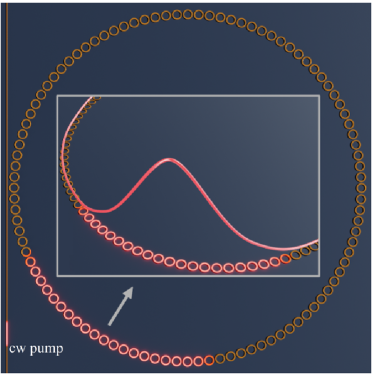
In this work, we propose a different approach to the generation of low threshold frequency combs in silicon at the telecom band. Our approach leverages structural slow light to enhance the non-linear processes, thereby requiring significantly lower values of the quality factor, which can be easily achieved with silicon microring structures. The system that we propose is illustrated in Fig. 1. It consists in a silica-encapsulated (SiO2) coupled-resonator optical waveguide (CROW) formed by coupled single-mode silicon microrings. This configuration takes advantage of structural slow-light Heebner and Boyd (2002); Minkov and Savona (2015); Lai et al. (2018) to effectively enhance the non-linearity of the material and consequently decrease the threshold power required to trigger cascaded FWM Bhat and Sipe (2001); Soljačić et al. (2002); Chen and Blair (2004); Santagiustina et al. (2010); Matsuda et al. (2011); Monat et al. (2009). We study this design both in terms of first-principle FDTD simulations and using a coupled-mode effective model that has proven extremely accurate for this kind of geometries Minkov and Savona (2015); Lai et al. (2018). The proposed Si/SiO2 CROW is found to support frequency combs and DKSs with pump power in the milliwatt range at telecom frequencies, with repetition rates as low as GHz and a small footprint of about mm2. We also investigate the effects of disorder, which are modeled both in terms of a reduced quality factor and by assuming randomly distributed resonant frequencies for the CROW modes. We find that DKS states are still possible in presence of disorder with standard deviation up to 1/16 of the CROW FSR, which is 20 times larger than the typical fluctuations found in standard state-of-the-art microring resonators. Our analysis opens the way to the realization of low-power DKS silicon devices operating at the telecommunication band.
The paper is organized as follows. In Sec. II, we survey the coupled-mode formalism, originally derived in Ref. Vasco and Savona (2019). We study the dispersion and intrinsic losses of the device in Sec. III. In Sec. IV, we compute the non-linear dynamics of the system to find the frequency comb and DKS solutions. The effect of disorder on the DKS states are analyzed in Sec. IV. The conclusions of this work are drawn in Sec. VI.
II Formalism
The set of equations describing the non-linear dynamics of the Bloch mode slowly-varying envelopes in a system of coupled Kerr resonators is given by Vasco and Savona (2019)
| (1) |
where is the total loss rate of the Bloch mode with momentum , is the detuning between the laser and mode frequencies, is the non-linear gain at the pumped mode frequency and is the pump amplitude. The rotating frame has been introduced in Eq. (II) setting . In presence of TPA, which is the main source of non-linear losses in silicon at telecom frequencies, is complex-valued and can be written as:
| (2) |
where is the the group index, is the single resonator non-linear mode volume, is the lattice period, and stand for the Kerr and TPA coefficients, respectively, of the material with dielectric constant , and is the speed of light in vacuum. Eq. (II) is normalized so that is the instantaneous power of the corresponding Bloch mode propagating along the CROW direction. This choice differs from the one usually adopted in microring resonators, where the squared modulus of the envelope function represents the instantaneous energy in the resonator mode (or photon number if given in units of ). Power normalization is the natural choice when the group velocity differs considerably from the phase velocity Santagiustina et al. (2010), and it is therefore the most appropriate choice for the present work focusing on the slow-light regime.
The coupling to an external bus waveguide is included by assuming that the total loss rate is the sum of the intrinsic radiative decay rate of the mode and the loss rate through the bus waveguide , i.e.,
| (3) |
We then use coupled mode theory Haus (1984) to establish the relation between the pump amplitude in Eq. (II) and the laser power
| (4) |
where is the total length of the waveguide of resonators. Equation (4) allows us to derive the external power threshold for frequency comb generation from the threshold of the internal field amplitude previously derived in Ref Vasco and Savona (2019)
| (5) |
In Eq. (5), is the coupling efficiency, which is equal to for critical coupling, and is a function of the material properties only, with . The minimum power threshold can be easily found by solving , leading to
| (6) |
where we have used the definition of from Eq. (2).
Equations (5) and (6) express the power threshold for comb generation in CROWs, in presence of TPA and slow-light. The latter is especially important due to inverse dependence of on the group index , which effectively enhances the Kerr non-linearity of the material and decreases the minimum power to trigger parametric FWM between the resonator modes. For typical microring resonators, the CROW system is replaced by a homogeneous waveguide, resulting in a group index which approaches the refractive index of the material, i.e., , and a total effective mode volume given by . If we further assume (i.e. no TPA limit), we recover from Eq. (6) the well known expression for the power threshold widely used for microring frequency combs Herr et al. (2014); Chembo (2016b)
| (7) |
III System and model
Whispering-gallery modes are efficiently confined within dielectric rings due to total internal reflection. The evanescent field immediately outside the ring typically decays over a short distance compared to the ring size, even when the refractive index contrast of the core-cladding is not large. This strong light confinement allows us to employ a tight-binding (TB) model in the weak and nearest-neighbor approximation to accurately describe our CROW system depicted in Fig. 1. The TB dispersion relation is analytical and given by Kamalakis and Sphicopoulos (2005)
| (8) |
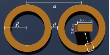
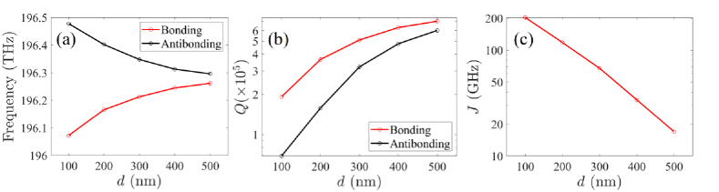
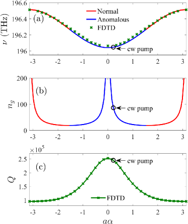
with denoting the mode frequency of the single rings and the coupling strength between two rings. Eq. (8) holds under the assumptions of single mode resonators and periodic boundary conditions. The former is fulfilled as long as the FSR of the microring is much larger than the TB bandwidth , which is easily achieved for small-size rings as discussed below. The latter applies to the closed loop of coupled rings, as shown in Fig. 1, resulting in negligible bending losses Yariv et al. (1999). In order to compute the model parameters and , we consider the system of two identical rings separated by a distance , as illustrated in Fig. 2. The rings have radius m, cross section nm2 and refractive index (silicon at telecom frequencies) Xiao et al. (2007). Additionally, the whole system is assumed to be encapsulated in silica (SiO2). Figure 3 shows the results obtained from first-principles FDTD calculations carried out with a commercial software lum (2020). The normal modes of the coupled rings, arising from the TE whispering-gallery mode at THz in each ring, are shown in Fig. 3(a). The fields of the bonding and anti-bonding modes are respectively even and odd under inversion with respect to the center of the system. We report in Fig. 3(b) the associated quality factors, which for large distance approach value of the uncoupled system, . The coupling strength , shown in Fig. 3(c), is extracted from Fig. 3(a) and is defined as half the normal-mode frequency separation. From FDTD simulations of the single resonator, we obtain a ring FSR of THz at the frequency , i.e. roughly five times larger than the largest value of considered, thus validating our assumption of single-mode coupling. We set the distance nm. This value is a good compromise between large coupling strength, low intrinsic normal mode losses and fabrication feasibility Bogaerts et al. (2012). For this distance, we infer from Fig. 3 GHz, (bonding) and (anti-bonding). We plot in Figs. 4(a) and 4(b) the corresponding dispersion relation [Eq. (8)] and group index , where m. As depicted in Fig. 1, a total number of microrings are considered. The resulting super-ring has radius m, the band being considered contains 100 Bloch modes. We computed the dispersion relation of the super-ring using FDTD. For this calculation we assumed an elementary computational cell containing a single ring and Bloch boundary condition along the main CROW axis. The computed dispersion is displayed in Fig. 4(a). The agreement with the TB result validates our nearest-neighbor coupling model. The quality factor of the band, extracted from these FDTD simulations, is reported in Fig. 4(c) and ranges from at the edges of the Brillouin zone, to close to . In order to achieve stimulated parametric FWM between the CROW modes, assisted by slow-light enhancement of the non-linear response, the system is driven at where and . We compute the minimum threshold power from Eq. (6) and obtain mW. For this calculation we used m3 obtained from FDTD calculations, , critical coupling to an external bus waveguide, and non-linear coefficients of silicon at telecom frequencies Hon et al. (2011), i.e., m2/W and m/W. This threshold value is comparable to the one of rings of size of several hundred micron, operating in the ultra-low loss regimes (quality factors of the order of ) Kippenberg et al. (2018).
The present CROW does not require ultra-high quality factors to generate parametric FWM at low threshold power, thanks to the structural slow-light factor entering Eqs. (5) and (6). Ultra-high quality factors, typically achieved in Si3N4 resonators, would be extremely challenging to realize in silicon rings due to propagation losses originating from surface roughness Hon et al. (2011); Ji et al. (2017). The device that we propose thus enables silicon as a material for the realization of comb devices. In what follows, we investigate the generation of frequency combs and DKS.
IV Slow-light frequency combs and DKS
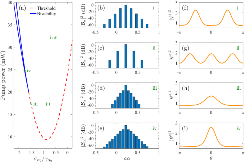
We plot in Fig. 5(a) the power threshold computed from Eq. (5) as a function of (dashed red), and the boundaries of the optical bistability region for the driven mode (continuous blue) Godey et al. (2014); Herr et al. (2014); Vasco and Savona (2019). We search for the steady state solutions of Eq. (II) by scanning the value of for different values of the pump power. The coupled-mode equations are integrated using an adaptive time step Runge-Kutta method and fast Fourier transform to efficiently compute the non-linear term T.Hansson et al. (2014). We take into account the -dependent quality factor from Fig. 4(c), with corresponding intrinsic loss rates and total loss rates given by at critical coupling. The pump field at time is assumed to have Gaussian shape along the CROW, where is the envelope function of the solution and is the polar angle denoting the position along the CROW. We show in Figs. 5(b)-5(e) four representative frequency combs found for the four values of pump power and detuning highlighted in Fig. 5(a). Figures 5(b)-5(c) correspond to super-critical Turing patters (they are excited above threshold) with 2-FSR and 3-FSR spacing, respectively. Fig. 5(d)-5(e) show sub-critical combs (excited below threshold) with single FSR spacing, which are the signature of soliton structures. The steady state envelope functions of these combs, denoted as , are shown in Figs. 5(f)-5(i). Two and three Turing rolls emerge respectively for the spectra with 2-FSR and 3-FSR spacing, in agreement with the Lugiato-Lefever model predictions Godey et al. (2014), while single solitons arise in the cases of 1-FSR spacing.
Even in presence of TPA, the present silicon CROW supports DKS structures at telecom frequencies and low power. This is achieved thanks to the non-linear enhancement provided by slow-light, which enable operating at significantly lower -values than those required in current microring resonators. The advantage brought by slow-light comes at the expense of the comb band-width, which is of the order of GHz with a repetition rate of GHz. Nevertheless, few-GHz repetition rates are desirable for applications in spectroscopy and signal processing in electronics Diddams (2010), and they are usually obtained in centimeter-size resonators Suh and Vahala (2018) – much larger than the m diameter of the present device.
V Effects of disorder
In order to study the robustness of our results against structural disorder arising at the fabrication stage, we model the effects of surface roughness by assuming a random deviation of the Bloch mode frequencies from the ideal values, and an additional loss channel. The quality factor associated to this additional loss channel is denoted by . The total quality factor of the ring mode, denoted as , is then computed as
| (9) |
with representing the FDTD-computed quality factor of the ideal system with perfect walls. As silica encapsulation smooths out structural imperfections at the ring surfaces Borselli et al. (2006); Vasco et al. (2020), a lower bound to the can be estimated from a silicon-on-insulator (SOI) configuration (where sidewalls are exposed directly to air). The total quality factor of the same ring geometry but in a SOI setup is reported in Ref. Xiao et al. (2007) with a value of . We then carry out the corresponding SOI simulation from which we obtain . Using and in Eq. (9) we get . Thereby, the normal mode quality factors of the CROW in presence of surface roughness, , can be approximated by assuming the lower bound of , i.e.
| (10) |
This increases the minimum power threshold of Eq. (6) from mW to mW, under critical coupling conditions ().
The effect of disorder on the frequencies of the Bloch modes is modeled as
| (11) |
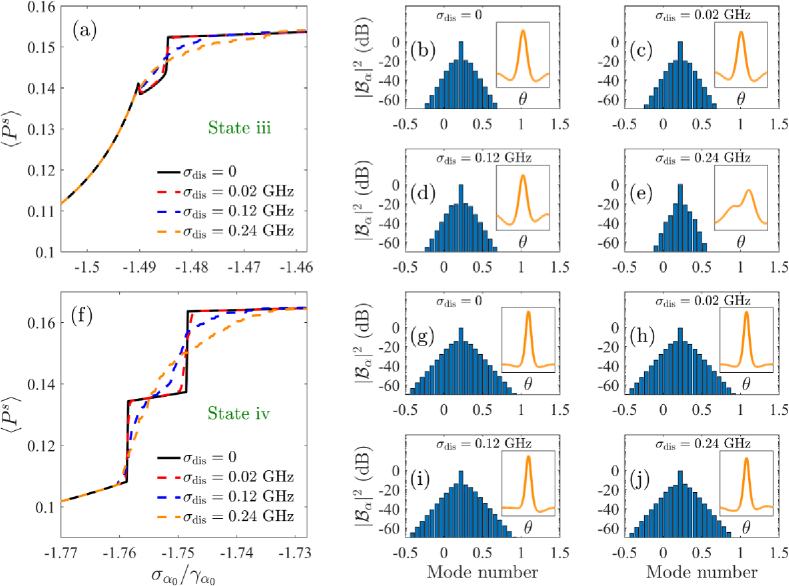
where are random fluctuations following a Gaussian probability distribution with standard deviation . This random term models random variations of both (due to sidewall roughness) and (due to imperfect positioning of the microring resonators). The new parameters and are introduced in the coupled-mode equations Eq. (II) which is solved under the same conditions as in Sec. IV. We first focus on the soliton state of Fig. 5(d) and plot in Fig. 6(a) the average of over an ensemble of 50 disorder realizations as a function of the laser detuning , for different values of . Notice that, for perfectly ordered frequencies, i.e., , where the effect of surface roughness is only considered on the quality factor of the CROW modes , the characteristic step in (signature of the soliton appearance) is still present but with a pump power increased from mW to mW. We show in Fig. 6(b) the frequency comb and corresponding envelope function in the inset along the super-ring polar angle at [same of Fig. 5(d)]. As disorder in the Bloch mode frequencies increases, the step in the averaged waveguide power becomes less evident thus making soliton states more unlikely to appear. Selected realizations for the different disorder magnitudes employed in this analysis are shown in Figs 6(c)-6(e). Here, we clearly see the effects of disorder on the soliton envelope, which starts to loss its spatial localization at GHz. We now focus on the state shown in Fig. 5(e), whose disorder analysis is presented in Fig. 6(f). In order to recover the same step features in presence of sidewall roughness, the pump power is increased from mW to mW. Selected realizations are also shown for this case in Figs. 6(g)-6(j) at [same of Fig. 5(e)]. Interestingly, for the largest disorder magnitude considered, the step in is still present and a spatially localized soliton envelope is more likely to appear than in Fig. 6(e), thus making this higher-power state more robust against random fluctuations on .
While disorder magnitudes of the order of GHz might be challenging to achieve in modern fabrication techniques, they are of the CROW FSR ( GHz), which is around 23 times the typical relative frequency fluctuation (with respect to the FSR) in modern microring resonators Brasch et al. (2016). Therefore, our results clearly evidence the extremely robust nature of DKS against random fluctuations on the resonator frequencies.
VI Conclusions
We have studied the formation of frequency combs and DKS in a CROW made of silica-encapsulated ring resonators, operating at telecommunication frequencies. Thanks to slow-light enhancement of the non-linear response of the CROW, combs and DKSs can be generated for significantly lower values of the quality factor, than those typically required by a microring resonator. These low values of the quality factor can be achieved in silicon structures even in presence of losses induced by surface roughness. Our study shows that combs and DKSs can arise already for pump power in the 10 mW range. This range of pump values also allows to rule out additional non-linear loss mechanisms due to free-carrier absorption at the 1.55 m band, which become relevant for input intensities larger than 10 GW/m2 Gai et al. (2013).
We have also addressed the effects of surface roughness and random frequency fluctuations arising from surface roughness introduced at the fabrication stage. Our results show that DKSs are robust against fabrication imperfections for values of the disorder amplitude well above those routinely achieved in microring resonators. The only effect of disoreder is a moderate increase of the power required for comb generation, due to the reduced quality factor.
The CROW structure that we propose opens the way to efficient, compact and low power comb and DKS generation in silicon devices at telecom frequencies.
References
- Chembo (2016a) Yanne K. Chembo, “Kerr optical frequency combs: theory, applications and perspectives,” Nanophotonics 5, 214 (2016a).
- Fortier and Baumann (2019) Tara Fortier and Esther Baumann, “20 years of developments in optical frequency comb technology and applications,” Commun. Phys. 2, 153 (2019).
- Gaeta et al. (2019) Alexander L. Gaeta, Michal Lipson, and Tobias J. Kippenberg, “Photonic-chip-based frequency combs,” Nat. Photonics 13, 158 (2019).
- Diddams et al. (2020) Scott A. Diddams, Kerry Vahala, and Thomas Udem, “Optical frequency combs: Coherently uniting the electromagnetic spectrum,” Science 369, 267 (2020).
- Trocha et al. (2018) P. Trocha, M. Karpov, D. Ganin, M. H. P. Pfeiffer, A. Kordts, S. Wolf, J. Krockenberger, P. Marin-Palomo, C. Weimann, S. Randel, W. Freude, T. J. Kippenberg, and C. Koos, “Ultrafast optical ranging using microresonator soliton frequency combs,” Science 359, 887 (2018).
- Newman et al. (2019) Z. Newman, V. Maurice, T. Drake, J. Stone, T. Briles, D. Spencer, C. Fredrick, Q. Li, D. Westly, B. Ilic, B. Shen, M. Suh, K. Yang, C. Johnson, D. Johnson, L. Hollberg, K. Vahala, Srinivasan K., S. Diddams, J. Kitching, S. Papp, and M. Hummon, “Architecture for the photonic integration of an optical atomic clock,” Optica 6, 680 (2019).
- Obrzud et al. (2019) Ewelina Obrzud, Monica Rainer, Avet Harutyunyan, Miles H. Anderson, Junqiu Liu, Michael Geiselmann, Bruno Chazelas, Stefan Kundermann, Steve Lecomte, Massimo Cecconi, Adriano Ghedina, Emilio Molinari, Francesco Pepe, François Wildi, François Bouchy, Tobias J. Kippenberg, and Tobias Herr, “A microphotonic astrocomb,” Nat. Photonics 13, 31 (2019).
- Spencer et al. (2018) Daryl T. Spencer, Tara Drake, Travis C. Briles, Jordan Stone, Laura C. Sinclair, Connor Fredrick, Qing Li, Daron Westly, B. Robert Ilic, Aaron Bluestone, Nicolas Volet, Tin Komljenovic, Lin Chang, Seung Hoon Lee, Dong Yoon Oh, Myoung-Gyun Suh, Ki Youl Yang, Martin H. P. Pfeiffer, Tobias J. Kippenberg, Erik Norberg, Luke Theogarajan, Kerry Vahala, Nathan R. Newbury, Kartik Srinivasan, John E. Bowers, Scott A. Diddams, and Scott B. Papp, “An optical-frequency synthesizer using integrated photonics,” Nature 557, 81 (2018).
- Coddington et al. (2016) Ian Coddington, Nathan Newbury, and William Swann, “Dual-comb spectroscopy,” Optica 3, 414 (2016).
- Picqué and Hänsch (2019) Nathalie Picqué and Theodor W. Hänsch, “Frequency comb spectroscopy,” Nat. Photonics 13, 146 (2019).
- Kippenberg et al. (2011) T. J. Kippenberg, R. Holzwarth, and S. A. Diddams, “Microresonator-based optical frequency combs,” Science 29, 555 (2011).
- Herr et al. (2012) T. Herr, K. Hartinger, J. Riemensberger, C. Y. Wang, E. Gavartin, R. Holzwarth, M. L. Gorodetsky, and T. J. Kippenberg, “Universal formation dynamics and noise of kerr-frequency combs in microresonators,” Nat. Photonics 6, 480 (2012).
- Godey et al. (2014) Cyril Godey, Irina V. Balakireva, Aurélien Coillet, and Yanne K. Chembo, “Stability analysis of the spatiotemporal lugiato-lefever model for kerr optical frequency combs in the anomalous and normal dispersion regimes,” Phys. Rev. A 89, 063814 (2014).
- Kippenberg et al. (2018) Tobias J. Kippenberg, Alexander L. Gaeta, Michal Lipson, and Michael L. Gorodetsky, “Dissipative kerr solitons in optical microresonators,” Science 361, 567 (2018).
- Herr et al. (2014) T. Herr, V. Brasch, J. D. Jost, C. Y. Wang, N. M. Kondratiev, M. L. Gorodetsky, and T. J. Kippenberg, “Temporal solitons in optical microresonators,” Nat. Photonics 8, 145 (2014).
- Ji et al. (2017) Xingchen Ji, Felippe A. S. Barbosa, Samantha P. Roberts, Avik Dutt, Jaime Cardenas, Yoshitomo Okawachi, Alex Bryant, Alexander L. Gaeta, and Michal Lipson, “Ultra-low-loss on-chip resonators with sub-milliwatt parametric oscillation threshold,” Optica 4, 619 (2017).
- Obrzud et al. (2017) Ewelina Obrzud, Steve Lecomte, and Tobias Herr, “Temporal solitons in microresonators driven by optical pulses,” Nat. Photonics 11, 600 (2017).
- Stern et al. (2018) Brian Stern, Xingchen Ji, Yoshitomo Okawachi, Alexander L. Gaeta, and Michal Lipson, “Battery-operated integrated frequency comb generator,” Nature 562, 401 (2018).
- Yu et al. (2018) Mengjie Yu, Yoshitomo Okawachi, Austin G. Griffith, Nathalie Picqué, Michal Lipson, and Alexander L. Gaeta, “Silicon-chip-based mid-infrared dual-comb spectroscopy,” Nat Commun. 9, 1869 (2018).
- Lau et al. (2015) Ryan K. W. Lau, Michael R. E. Lamont, Yoshitomo Okawachi, and Alexander L. Gaeta, “Effects of multiphoton absorption on parametric comb generation in silicon microresonators,” Opt. Lett. 40, 2778 (2015).
- Bogaerts et al. (2012) W. Bogaerts, P. De Heyn, T. Van Vaerenbergh, K. De Vos, S. Kumar Selvaraja, T. Claes, P. Dumon, P. Bienstman, D. Van Thourhout, and R. Baets, “Silicon microring resonators,” Laser Photonics Rev. 6, 47 (2012).
- Heebner and Boyd (2002) John E. Heebner and Robert W. Boyd, “Slow and stopped light ’slow’ and ’fast’ light in resonator-coupled waveguides,” J. Mod. Opt 49, 2629 (2002).
- Minkov and Savona (2015) Momchil Minkov and Vincenzo Savona, “Wide-band slow light in compact photonic crystal coupled-cavity waveguides,” Optica 2, 631 (2015).
- Lai et al. (2018) Yiming Lai, Mohamed Sabry Mohamed, Boshen Gao, Momchil Minkov, Robert W. Boyd, Vincenzo Savona, Romuald Houdré, and Antonio Badolato, “Ultra-wide-band structural slow light,” Sci. Rep. 8, 14811 (2018).
- Bhat and Sipe (2001) N. A. R. Bhat and J. E. Sipe, “Optical pulse propagation in nonlinear photonic crystals,” Phys. Rev. E 64, 056604 (2001).
- Soljačić et al. (2002) Marin Soljačić, Steven G. Johnson, Shanhui Fan, Mihai Ibanescu, Erich Ippen, and J. D. Joannopoulos, “Photonic-crystal slow-light enhancement of nonlinear phase sensitivity,” J. Opt. Soc. Am. B 19, 2052 (2002).
- Chen and Blair (2004) Yan Chen and Steve Blair, “Nonlinearity enhancement in finite coupled-resonator slow-light waveguides,” Opt. Express 12, 3353 (2004).
- Santagiustina et al. (2010) M. Santagiustina, C. G. Someda, G. Vadalà, S. Combrié, and A. De Rossi, “Theory of slow light enhanced four-wave mixing in photonic crystal waveguides,” Opt. Express 18, 21024 (2010).
- Matsuda et al. (2011) Nobuyuki Matsuda, Takumi Kato, Ken-ichi Harada, Hiroki Takesue, Eiichi Kuramochi, Hideaki Taniyama, and Masaya Notomi, “Slow light enhanced optical nonlinearity in a silicon photonic crystal coupled-resonator optical waveguide,” Opt. Express 19, 19861 (2011).
- Monat et al. (2009) Christelle Monat, Bill Corcoran, Majid Ebnali-Heidari, Christian Grillet, Benjamin J. Eggleton, Thomas P. White, Liam O’Faolain, and Thomas. F. Krauss, “Slow light enhancement of nonlinear effects in silicon engineered photonic crystal waveguides,” Opt. Express 17, 2944 (2009).
- Vasco and Savona (2019) J.P. Vasco and V. Savona, “Slow-light frequency combs and dissipative kerr solitons in coupled-cavity waveguides,” Phys. Rev. Applied 12, 064065 (2019).
- Haus (1984) H. A. Haus, Waves and Fields in Optoelectronics (Englewood Cliffs, 1984) Chap. 7.
- Chembo (2016b) Yanne K. Chembo, “Quantum dynamics of kerr optical frequency combs below and above threshold: Spontaneous four-wave mixing, entanglement, and squeezed states of light,” Phys. Rev. A 93, 033820 (2016b).
- Kamalakis and Sphicopoulos (2005) T. Kamalakis and T. Sphicopoulos, “Analytical expressions for the resonant frequencies and modal fields of finite coupled optical cavity chains,” IEEE J. Quantum Electron 41, 1419 (2005).
- Yariv et al. (1999) Amnon Yariv, Yong Xu, Reginald K. Lee, and Axel Scherer, “Coupled-resonator optical waveguide: a proposal and analysis,” Opt. Lett. 24, 711 (1999).
- Xiao et al. (2007) Shijun Xiao, Maroof H. Khan, Hao Shen, and Minghao Qi, “Compact silicon microring resonators with ultra-low propagation loss in the c band,” Opt. Express 15, 14467 (2007).
- lum (2020) Lumerical Solutions, Inc. (2020).
- Hon et al. (2011) Nick K. Hon, Richard Soref, and Bahram Jalali, “The third-order nonlinear optical coefficients of si, ge, and si1-xgex in the midwave and longwave infrared,” J. Appl. Phys. 110, 011301 (2011).
- T.Hansson et al. (2014) T.Hansson, D.Modotto, and S.Wabnitz, “On the numerical simulation of kerr frequency combs using coupled mode equations,” Opt. Commun. 312, 134 (2014).
- Diddams (2010) Scott A. Diddams, “The evolving optical frequency comb,” J. Opt. Soc. Am. B 27, B51 (2010).
- Suh and Vahala (2018) Myoung-Gyun Suh and Kerry Vahala, “Gigahertz-repetition-rate soliton microcombs,” Optica 5, 65 (2018).
- Borselli et al. (2006) Matthew Borselli, Thomas J. Johnson, and Oskar Painter, “Measuring the role of surface chemistry in silicon microphotonics,” Appl. Phys. Lett. 88, 131114 (2006).
- Vasco et al. (2020) J.P. Vasco, D. Gerace, K. Seibold, and V. Savona, “Monolithic silicon-based nanobeam cavities for integrated nonlinear and quantum photonics,” Phys. Rev. Applied 13, 034070 (2020).
- Brasch et al. (2016) V. Brasch, M. Geiselmann, T. Herr, G. Lihachev, M. H. P. Pfeiffer, M. L. Gorodetsky, and T. J. Kippenberg, “Photonic chip–based optical frequency comb using soliton cherenkov radiation,” Science 351, 357 (2016).
- Gai et al. (2013) Xin Gai, Yi Yu, Bart Kuyken, Pan Ma, Steve J. Madden, Joris Van Campenhout, Peter Verheyen, Gunther Roelkens, Roel Baets, and Barry Luther-Davies, “Nonlinear absorption and refraction in crystalline silicon in the mid‐infrared,” Laser Photon. Rev. 7, 1054 (2013).