Multi-kT/m Focusing Gradient in a Linear Active Plasma Lens
Abstract
Active plasma lenses are compact devices developed as a promising beam-focusing alternative for charged particle beams, capable of short focal lengths for high-energy beams. We have previously shown that linear magnetic fields with gradients of around 0.3 kT/m can be achieved in argon-filled plasma lenses that preserve beam emittance [C.A. Lindstrøm et al., Phys. Rev. Lett. 121, 194801 (2018)]. Here we show that with argon in a 500 diameter capillary, the fields are still linear with a focusing gradient of 3.6 kT/m, which is an order of magnitude higher than the gradients of quadrupole magnets. The current pulses that generate the magnetic field are provided by compact Marx banks, and are highly repeatable. These results establish active plasma lenses as an ideal device for pulsed particle beam applications requiring very high focusing gradients that are uniform throughout the lens aperture.
Plasma-based technology promises to pave the way for more compact particle accelerators [1]. While much research has been directed towards the use of plasma technology for compact acceleration [2, 3, 4], there has been less effort directed at compactifying the focusing elements of the accelerator, which is also crucial for achieving compact machines. The development of plasma lenses, as discussed here, may establish a superior beam-focusing alternative for charged particle beams in high energy physics applications, as well as for other demanding pulsed-beam applications such as medical applications or photon sources [5, 6, 7].
Quadrupole magnetic lenses are the conventional choice for focusing of high-energy charged beams [8, Section 7.2]. Permanent quadrupole magnets can be made compact and precise [9], but the focusing gradient is currently limited to several 100 T/m [9, 10], and they have a limited tuning range. Furthermore, a quadrupole defocuses the beam in the plane orthogonal to the focusing plane, requiring a lattice of several magnets to achieve an overall focusing effect. Active plasma lenses [11, 12] (APLs) generate a focusing magnetic field by passing a strong current through a plasma that is parallel to and overlapping with the beam axis, creating an axisymmetric focusing force. Axisymmetric focusing is particularly important for capturing and re-focusing beams with high divergence and energy spread, e.g. a beam produced in a plasma wakefield accelerator [4, 13]. High gradient is important to minimize the length of the focusing device; e.g. for a 100 GeV electron beam, a 10 cm long plasma lens with gradient of 3 kT/m would have a focal length of 1 m, whereas the focal length for a quadrupole magnet of the same physical length would be m. Implementations of APLs using discharge capillary technology [14] have recently been developed [11, 15], and first uses as optical elements for accelerator research applications are reported [16, 17, 18].
A challenge for APLs are different sources of nonlinearity in the fields, mainly due to nonuniform plasma heating [19] and wakefields [20]. Recent work has shown that the these nonlinearities can be avoided, and that active plasma lensing with linear focusing forces can be achieved [21, 16], which is necessary to preserve beam emittance. Historically, very high gradients have been reached in -pinch-discharge APLs [22, 23], however these devices did not produce a linear focusing magnetic field. More recently gradients of have been demonstrated without pinching, however this was in a nonlinear hydrogen lens with a small diameter of 250 [11].
When increasing the magnetic field gradient in an APL, several technical and physical challenges must be overcome in order to produce a useful device. Our experiment pushes the demonstrated gradients by developing compact high voltage sources with fast and reproducible pulses, while still avoiding both the thermal nonlinearities seen for light gases such as helium [24, 25, 19, 26], and the pinching of the field-producing current stream in the plasma [27]. Our results demonstrate that APLs may repeatably operate at multi-kT/m gradients, outperforming quadrupole magnets, and at the same time provide linear focusing forces. The results therefore represents a key step for establishing the APL as a versatile and useful device for compact, pulsed-beam applications.
I Experimental setup
The CLEAR Plasma Lens Experiment [15, 21, 28] is installed at the CLEAR user facility at CERN [29, 30, 31], using a 200 MeV linear electron accelerator to produce beams with a large range of parameters.
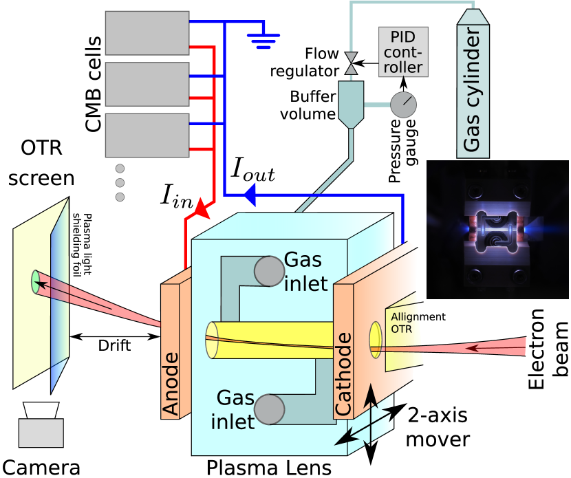
The principle of the experiment is illustrated in Fig. 1. First, a strongly focused beam enters the capillary, in order to probe the field in a small region. This beam is then deflected towards the center of the lens by the focusing force. After exiting the lens, there is a short drift before the beam impinges on an optical transition radiation (OTR) screen mounted at a angle to the beam, used to measure the beam position. This screen is shielded from the light emitted from the plasma with a thin metallized polymer foil; this limits us to only measuring vertical beam deflection, as otherwise the distance between the foil and the screen changes as the beam moves across it, causing a change in the apparent beam shape.
A small OTR screen is mounted on the upstream electrode in order to aid focusing the beam and aligning the lens to the beam, as shown in Fig. 1. The electron beam was focused down to a horizontal vertical size of RMS as measured on the alignment OTR and by the fall-off of beam intensity as a function of lens position when scanning the aperture edge over the beam. This allows the beam to pass cleanly through the capillary containing the current-carrying plasma and to sample the field locally.
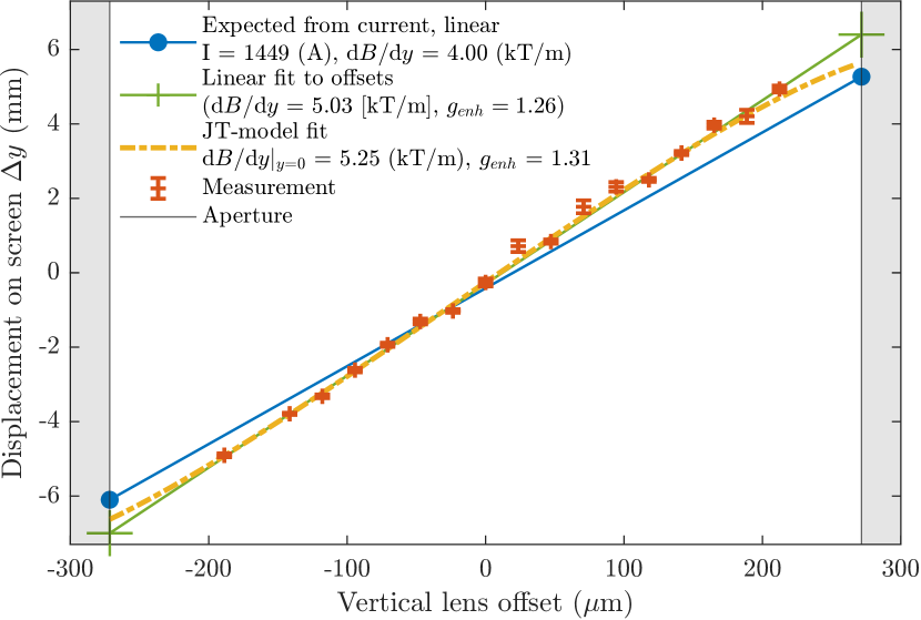
In order to measure the magnetic field in the lens as a function of position, the lens is moved transversely relatively to the beam. The beam position on the OTR screen is then measured as a function of the lens position, and compared to the beam position without discharge in order to measure the deflection. The magnetic field gradient can then be reconstructed as discussed in Appendix A; due to the very high gradients, the plasma lens must be treated as a thick lens because the focal length ( 20 mm from lens entrance) is on the order of the length of the lens.
Furthermore, the gradient enhancement was measured as a function of time, by holding the lens at a known position and changing the relative timing of the lens with respect to the beam. The gradient enhancement was then found by comparing the deflection expected from the current measurement with the one observed on the screen, as described in detail in Appendix D.
I.1 Discharge capillary
The discharges are contained within a sapphire capillary, as shown in the insert in Fig. 1. For the experiments reported in this paper, a 15 mm long capillary with a nominal diameter of 500 was used. It is made by milling out a semicircular groove in two sapphire plates which are then pressed together. For small-diameter capillaries, the manufactured capillary may not be perfectly round; this is taken into account when computing the expected gradient from the current as explained in Appendix A as well as for modeling the nonlinearity in helium as described in Appendix B.
The capillary is supplied with gas at an adjustable pressure through two inlet channels, giving a flat initial pressure profile between these channels. In order to maintain the accelerator vacuum, a turbo-pump removes the gas escaping from the capillary openings, and a 3 Mylar beam window is used to separate the plasma lens chamber from the upstream accelerator vacuum.
The breakdown voltage and drive current pulse is supplied via a set of copper electrodes on each end of the capillary, with holes that allow the beam to pass in and out of the channel.
I.2 Compact Marx Bank
The high voltage required to first form the conducting plasma and then drive the high currents needed for our high-gradient lens were provided by Compact Marx Bank (CMB) cells [32]. These were connected in parallel, with each CMB cell consisting of a 10-stage ladder network with capacitor rungs initially charged to . This gives a floating initial discharge voltage of with an effective cell capacitance of 4.4 nF (about 1 J per discharge). This voltage is higher than that strictly needed for gas breakdown, since this ensures a rapid onset of the discharge within a few ns of the voltage pulse being applied. Once the plasma is formed the current pulse starts to climb, mainly constrained by circuit inductance.
The CMB cells are arranged on a single chassis in banks of four and enclosed in a box. Up to 8 cells were used, placed a within a few from plasma lens. The cells provide high-current pulses with sub- duration and fast rise time as shown in Fig. 2, appropriate for driving a plasma lens while limiting the total amount of energy deposited in each pulse to reduce capillary damage by heating. The close proximity of the mounting is necessary to eliminate the need for impedance matching.
Combining several cells in parallel brings a number of advantages. Firstly the total current is increased according to the number of cells used and thus the gradient. Simultaneously the jitter in both timing and peak current is reduced. Furthermore, the reliability is also increased, as the current drawn from each cell is reduced to below 200 A, and in the case of the loss of a single cell the lens can still operate in a degraded peak current mode.
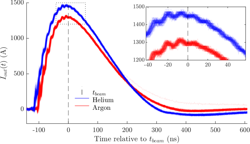
The current output of the CMBs are measured by two current-pulse transformers; one on each cable in order to detect large losses to ground. The current traces during the offset scans described in the next section are shown in Fig. 2. This shows that the current rises from 0 to peak in ns, has a flat-top of a few 10s of ns, before it falls off in ns. For both argon and helium the incoming and outgoing currents at the time of beam arrival are identical, and their standard deviation are both equal to the sampling resolution, which is 8 A. In general the current pulses are highly reproducible.
II Magnetic field gradient measurements
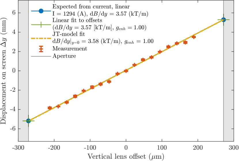
The field measurements were done in both argon and helium, and the lens was operated at a neutral gas pressure in the buffer volume of 25 mbar and 55 mbar respectively. These were the minimum values for stable operation of the discharge in the 0.5 mm capillary used here. The expected pressure in the capillary is then approximately 8 mbar for argon and 17 mbar for helium [21]. The beam energy was 195 MeV, using three bunches for a total train length of 2 , each with a bunch length 4 ps rms, and a total charge of 200 pC. The beam size on the screen soon after the current had returned to zero was the same as before plasma ignition, indicating negligible influence from plasma wakefields [20]. This relatively high beam charge was necessary to be able to measure the beam position on the OTR screen in spite of the strong over-focusing in the lens, causing a diffuse beam with a size of at this location. The large size made the accurate reconstruction of the beam position more difficult, contributing to the errorbars seen in Figs. 3 and 5, which indicate the standard error of the mean reconstructed beam position. The field was measured only in the central 400 of the capillary; in the last from the edge the beam was deflected outside the screen.
The beam displacement as function of position for argon is shown in Fig. 3. The measured gradient from a linear fit was found to be kT/m, where the error estimate is the standard deviation due to the uncertainty of the position measurements. No evidence of a gradient enhancement [19] near the center was observed when fitting a nonlinear model.
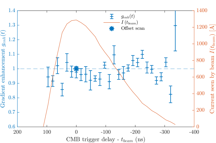
The measurement of gradient enhancement as a function of time is shown in Fig. 4. This shows that the gradient enhancement remained constant throughout the discharge; the weighted average being .
For helium the beam displacement as function of position is shown in Fig. 5, where the observed central gradient was kT/m. Here the nonlinear model found a gradient enhancement of %, where the error is the standard deviation due to the uncertainity of the position measurements.
III Discussion
The central focusing gradients were obtained directly from the beam deflection measurement, using fits based on the measured current and geometry and the corrected mover positions. For argon the results indicate that even at these very high gradients, APLs remain linear throughout the time- and aperture range that we tested, which is a necessary condition for emittance preservation. For helium the observed gradient enhancement factor is statistically consistent with the 34% found earlier [21, 28] at a central lower gradient 440 T/m, using a 1000 diameter capillary and single CMB cell producing a peak current of 410 A.
The gradient enhancement factor in argon was also measured as a function of time, confirming that it remains constant and close to unity throughout the duration of the discharge. This implies that the gradient can be fine-tuned simply by changing the timing of the discharge, without incurring nonlinearity.
In earlier work [20] it has been shown that beams with high charge density can create waves in the plasma, which in turn may lead to nonlinear fields. The relative effect of the wakes may be reduced by increasing the plasma lens gradient [33], hence our results increase the parameter range where APLs with linear fields can be used.
Another potential source of nonlinearities is the -pinching of the current in the plasma lens, due to the magnetic pressure overcoming the gas pressure in the plasma. This will tend to concentrate the current on axis, forming a nonlinear and potentially unstable field from the concentrated current [27, 34]. We did not observe any indication that this was the case here, possibly due to the short duration of the peak current.
The group of experimental CMB cells reached very high currents without any major failures. The addition of several of these in parallel tended to stabilize the discharge compared to previous experiments, and reduced the failure rate of the system as less current was drawn from each CMB cell. This principle allows for coarse tunability of the total current and redundancy in the system by overprovisioning the number of cells needed for the nominally required current.
While the inner surfaces of the capillaries appeared darker after carrying discharges with currents, we did not observe any degradation of performance during the experiment. However, before application of high gradient plasma lenses more systematic studies of the capillary damage should be performed in order to ensure long-term stability.
IV Conclusion
We demonstrate the operation of a compact, linear APL in argon with a focusing gradient of 3.6 kT/m. With helium as the fill gas the lens is nonlinear with a central gradient of 5.3 kT/m. The lens has a 500 diameter and is powered by compact Marx banks (CMB) cells connected in parallel.
The use of CMB cells enable us to reach the high currents required to drive the lens with short-duration pulses. This presents compact power source that can reach even higher currents by simply adding more cells.
This opens up the possibility for the use of APLs in applications requiring gradients well beyond those of quadrupole magnets, or that otherwise benefit from a strong axisymmetric linear focusing element.
Acknowledgements.
We thank CERN for providing beam time at the CLEAR User Facility, and especially A. Gillardi, D. Gamba, A. Curcio, A. Chauchet, S. Curt, G. McMonagle, S. Burger, M. Bergamaschi, T. Lefevre, E. Granados, and H. Panuganti, for making it possible to run the accelerator, and for often lending us a hand and suggestions for improving the experiment. We also thank S. Hooker for suggestions for improving the manuscript. This work was supported by the Research Council of Norway (NFR Grant No. 255196/F50) and the Helmholtz Association of German Research Centers (Grants No. VH-VI-503 and No. ZT-0009).Appendix A Magnetic field in elliptical capillaries
The capillaries are produced by milling sapphire plates using a ball mill cutter with the same diameter as the capillary, which should plunge exactly 1/2 of the milling bit diameter. In practice the machining precision can be at a level where small diameter capillaries are noticeably oval. This distributes the current over a larger area, causing a reduction of the gradient that is different between the horizontal- and vertical planes. For the capillary used in this paper, the diameters were measured using optical profilometry to be 525 horizontally and 543 vertically.
Working in an elliptical coordinate system , where are the elliptical half-axis and , we will make the assumption that both the magnetic field component and the current density is independent of the polar angle . Applying Ampere’s law on loops of constant , we find that
| (1) |
where is the circumference of an ellipse with the same flattening as the capillary itself, which can be estimated with Ramanujan’s formula
For the case of a uniform current density, the expected horizontal field gradient in an elliptical capillary is then
| (2) |
and similar for the vertical plane by substituting , where . This approximation was used when computing the expected gradient . Through simulation, it was verified that for a flattening and a uniform , the agreement between the resulting analytical formula in Eq. 2 and the simulation was better than 1%.
Appendix B model in elliptical capillary
The JT-model [19, 24, 21] describes how a gradient nonuniformity can be caused by a radial variation of the electron temperature in the capillary, where is a constant given by the capillary size and plasma parameters, and is a solution to the heat flow equation
| (3) |
This causes a variation of the conductivity , which causes the nonuniformity of the current density , creating the nonlinearity of . Combining these gives , where the unknown constant can be determined through conservation of current , and through solving Eq. 3.
Appendix C Magnetic field gradient measurement technique considering thick-lens effect
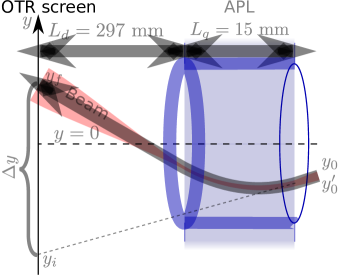
The measurement of the magnetic gradient is based on measuring the deflection of a particle beam passing through the lens, as illustrated in Fig. 6. The position of the beam on the downstream profile monitor is compared between the case where the plasma lens is on and off, giving a deflection .
Because the focal length of the lens is short compared to the length of the lens, the thick-lens effect must be taken into account to correctly find the gradient. The position on the screen is given by
| (5) |
where the focusing strength is
The deflection on the screen is thus given as
| (6) |
where is a constant term due to the initial beam angle , and is the position on the screen when . Note that in the experiment the lens itself was moved relative to the beam, which mathematically is equivalent to shifting the point where and thus shifting both and in the opposite direction of the lens movement.
In order to find the strength and thus the gradient seen by the beam , we measure the deflection as a function of the initial position and numerically find the root of
| (7) |
The method was tested by reversing the current direction in the lens, running it in the defocusing mode with argon gas. In this case, the beam is pushed outwards while traversing the lens, increasing the kick instead of decreasing it; however the same focusing gradient was measured in the reversed case as in the normal case when other parameters were kept constant.
In order to apply this method to a nonlinear thick elliptical lens with a field distribution given by Eqs. 4 and 1, a numerical tracking method is used instead of equation 5 to track the beam centroid through the lens. For this, the lens is sliced into 1 mm thick slices, and the field seen by the beam centroid is computed at each slice. The computed deflection is then fitted to the data, using the initial angle and the central normalized temperature as free parameters, and the measured current and geometry as input.
Appendix D Field enhancement time development considering thick-lens effect
For measuring how the gradient enhancement develops in time, timing scans are used. In these, the trigger of the CMBs are scanned relative to the time of arrival of the beam so that the beam probes the discharge at different times. For these experiments, the position of the lens and the initial beam position is kept constant; if assuming a linear lens the centroid position on the final screen is then given by Equation 5. This depends on three parameters: The focusing strength , and the initial beam position and angle relative to the lens axis. In the experiment is known as the lens mover is well calibrated when ran without discharge, and the center is found as the lens position where the centroid kick is zero, and verified as being in the center of the aperture. This procedure works well as long as is small, which is ensured during beam setup by varying the beam angle in order to maximize the apparent beam aperture through the capillary.
By measuring the beam deflection at several and assuming that is constant and , the initial beam angle and the overall gradient enhancement can be found through a nonlinear least-squares fit, finding and . The angle is also small enough that the reduction of apparent aperture over the length of the 15 mm long capillary would be barely noticeable; it is also robust as if locking and fitting and , a position of –147 and an angle of –0.84 mrad.
Once the initial position and angle is established, the actual strength and thus the can be found for each time-point by solving Equation 5 for and computing . Comparing this to the expected gradient in case of a uniform current then gives an estimate of the gradient enhancement as a function of time, as shown in Fig. 4; even if the original fit was made under the assumption of , a time development would still be expected to be apparent. The errorbars on the gradient enhancement is the estimated standard deviation derived from a combination of 1 ns uncertainty on the time of sampling the current for the calculation of , and the uncertainty on the mean beam position on the screen at each timing for the calculation of .
References
- Joshi and Katsouleas [2003] C. Joshi and T. Katsouleas, Plasma Accelerators at the Energy Frontier and on Tabletops, Physics Today 56, 47 (2003), publisher: American Institute of Physics.
- Cros and Patric [2017] B. Cros and M. Patric, Towards a Proposal for an Advanced Linear Collider, Tech. Rep. (ICFA Advanced and Novel Accelerators Panel, 2017).
- Schulte [2016] D. Schulte, Application of Advanced Accelerator Concepts for Colliders, Reviews of Accelerator Science and Technology 09, 209 (2016).
- Lindstrøm et al. [2016] C. A. Lindstrøm, E. Adli, J. M. Allen, J. P. Delahaye, M. J. Hogan, C. Joshi, P. Muggli, T. O. Raubenheimer, and V. Yakimenko, Staging optics considerations for a plasma wakefield acceleration linear collider, Nuclear Instruments and Methods in Physics Research Section A: Accelerators, Spectrometers, Detectors and Associated Equipment 2nd European Advanced Accelerator Concepts Workshop - EAAC 2015, 829, 224 (2016).
- Joshi et al. [2020] C. Joshi, S. Corde, and W. B. Mori, Perspectives on the generation of electron beams from plasma-based accelerators and their near and long term applications, Physics of Plasmas 27, 070602 (2020), publisher: American Institute of Physics.
- Couprie [2018] M. E. Couprie, Towards compact Free Electron–Laser based on laser plasma accelerators, Nuclear Instruments and Methods in Physics Research Section A: Accelerators, Spectrometers, Detectors and Associated Equipment 3rd European Advanced Accelerator Concepts workshop (EAAC2017), 909, 5 (2018).
- Maier et al. [2020] A. R. Maier, M. Kirchen, and F. Grüner, Brilliant Light Sources Driven by Laser-Plasma Accelerators, in Synchrotron Light Sources and Free-Electron Lasers: Accelerator Physics, Instrumentation and Science Applications, edited by E. J. Jaeschke, S. Khan, J. R. Schneider, and J. B. Hastings (Springer International Publishing, Cham, 2020) pp. 245–270.
- Alexander Wu Chao et al. [2013] Alexander Wu Chao, Karl Hubert Mess, Maury Tigner, and Frank Zimmermann, Handbook of Accelerator Physics and Engineering, 2nd ed. (World Scientific Publishing Co. Pte. Ltd., 2013).
- Becker et al. [2009] S. Becker, M. Bussmann, S. Raith, M. Fuchs, R. Weingartner, P. Kunz, W. Lauth, U. Schramm, M. El Ghazaly, F. Grüner, H. Backe, and D. Habs, Characterization and tuning of ultrahigh gradient permanent magnet quadrupoles, Physical Review Special Topics - Accelerators and Beams 12, 102801 (2009), publisher: American Physical Society.
- Modena et al. [2012] M. Modena, O. Dunkel, J. G. Perez, C. Petrone, P. A. Thonet, and D. Tommasini, Design, Assembly and First Measurements of a Short Model for CLIC Final Focus Hybrid Quadrupole QD0, in Proceedings of IPAC2012, New Orleans, Louisiana, USA (2012) p. 3.
- van Tilborg et al. [2015] J. van Tilborg, S. Steinke, C. Geddes, N. Matlis, B. Shaw, A. Gonsalves, J. Huijts, K. Nakamura, J. Daniels, C. Schroeder, C. Benedetti, E. Esarey, S. Bulanov, N. Bobrova, P. Sasorov, and W. Leemans, Active Plasma Lensing for Relativistic Laser-Plasma-Accelerated Electron Beams, Physical Review Letters 115, 184802 (2015).
- Panofsky and Baker [1950] W. K. H. Panofsky and W. R. Baker, A Focusing Device for the External 350‐Mev Proton Beam of the 184‐Inch Cyclotron at Berkeley, Review of Scientific Instruments 21, 445 (1950).
- Migliorati et al. [2013] M. Migliorati, A. Bacci, C. Benedetti, E. Chiadroni, M. Ferrario, A. Mostacci, L. Palumbo, A. R. Rossi, L. Serafini, and P. Antici, Intrinsic normalized emittance growth in laser-driven electron accelerators, Physical Review Special Topics - Accelerators and Beams 16, 011302 (2013).
- Spence and Hooker [2000] D. J. Spence and S. M. Hooker, Investigation of a hydrogen plasma waveguide, Physical Review E 63, 015401 (2000), publisher: American Physical Society.
- Lindstrøm et al. [2018a] C. A. Lindstrøm, K. N. Sjobak, E. Adli, J. H. Röckemann, L. Schaper, J. Osterhoff, A. E. Dyson, S. M. Hooker, W. Farabolini, D. Gamba, and R. Corsini, Overview of the CLEAR plasma lens experiment, Nuclear Instruments and Methods in Physics Research Section A: Accelerators, Spectrometers, Detectors and Associated Equipment 3rd European Advanced Accelerator Concepts workshop (EAAC2017), 909, 379 (2018a).
- Pompili et al. [2018] R. Pompili, M. Anania, M. Bellaveglia, A. Biagioni, S. Bini, F. Bisesto, E. Brentegani, F. Cardelli, G. Castorina, E. Chiadroni, A. Cianchi, O. Coiro, G. Costa, M. Croia, D. Di Giovenale, M. Ferrario, F. Filippi, A. Giribono, V. Lollo, A. Marocchino, M. Marongiu, V. Martinelli, A. Mostacci, D. Pellegrini, L. Piersanti, G. Di Pirro, S. Romeo, A. Rossi, J. Scifo, V. Shpakov, A. Stella, C. Vaccarezza, F. Villa, and A. Zigler, Focusing of High-Brightness Electron Beams with Active-Plasma Lenses, Physical Review Letters 121, 10.1103/PhysRevLett.121.174801 (2018).
- Steinke et al. [2016] S. Steinke, J. van Tilborg, C. Benedetti, C. G. R. Geddes, C. B. Schroeder, J. Daniels, K. K. Swanson, A. J. Gonsalves, K. Nakamura, N. H. Matlis, B. H. Shaw, E. Esarey, and W. P. Leemans, Multistage coupling of independent laser-plasma accelerators, Nature 530, 190 (2016).
- Barber et al. [2020] S. K. Barber, J. H. Bin, A. J. Gonsalves, F. Isono, J. van Tilborg, S. Steinke, K. Nakamura, A. Zingale, N. A. Czapla, D. Schumacher, C. B. Schroeder, C. G. R. Geddes, W. P. Leemans, and E. Esarey, A compact, high resolution energy, and emittance diagnostic for electron beams using active plasma lenses, Applied Physics Letters 116, 234108 (2020).
- van Tilborg et al. [2017] J. van Tilborg, S. Barber, H.-E. Tsai, K. Swanson, S. Steinke, C. Geddes, A. Gonsalves, C. Schroeder, E. Esarey, S. Bulanov, N. Bobrova, P. Sasorov, and W. Leemans, Nonuniform discharge currents in active plasma lenses, Physical Review Accelerators and Beams 20, 032803 (2017).
- Lindstrøm and Adli [2018] C. A. Lindstrøm and E. Adli, Analytic plasma wakefield limits for active plasma lenses, arXiv:1802.02750 [physics] (2018), arXiv: 1802.02750.
- Lindstrøm et al. [2018b] C. Lindstrøm, E. Adli, G. Boyle, R. Corsini, A. Dyson, W. Farabolini, S. Hooker, M. Meisel, J. Osterhoff, J.-H. Röckemann, L. Schaper, and K. Sjobak, Emittance Preservation in an Aberration-Free Active Plasma Lens, Physical Review Letters 121, 194801 (2018b).
- Autin et al. [1987] B. Autin, H. Riege, E. Boggasch, K. Frank, L. D. Menna, and G. Miano, A Z-Pinch Plasma Lens for Focusing High-Energy Particles in an Accelerator, IEEE Transactions on Plasma Science 15, 226 (1987).
- Christiansen et al. [1984] J. Christiansen, K. Frank, H. Riege, and R. Seeböck, Studies of plasma lens with pseudo-spark geometry for application in high-energy particle accelerators, Tech. Rep. 84-10-AA (CERN, 1984).
- Bobrova et al. [2001] N. A. Bobrova, A. A. Esaulov, J.-I. Sakai, P. V. Sasorov, D. J. Spence, A. Butler, S. M. Hooker, and S. V. Bulanov, Simulations of a hydrogen-filled capillary discharge waveguide, Physical Review E 65, 10.1103/PhysRevE.65.016407 (2001).
- Broks et al. [2005] B. H. P. Broks, K. Garloff, and J. J. A. M. van der Mullen, Nonlocal-thermal-equilibrium model of a pulsed capillary discharge waveguide, Physical Review E 71, 10.1103/PhysRevE.71.016401 (2005).
- Röckemann et al. [2018] J.-H. Röckemann, L. Schaper, S. Barber, N. Bobrova, G. Boyle, S. Bulanov, N. Delbos, K. Floettmann, G. Kube, W. Lauth, W. Leemans, V. Libov, A. Maier, M. Meisel, P. Messner, P. Sasorov, C. Schroeder, J. van Tilborg, S. Wesch, and J. Osterhoff, Direct measurement of focusing fields in active plasma lenses, Physical Review Accelerators and Beams 21, 122801 (2018).
- Bennett [1934] W. H. Bennett, Magnetically Self-Focussing Streams, Physical Review 45, 890 (1934).
- Lindstrøm et al. [2019] C. Lindstrøm, E. Adli, G. Boyle, R. Corsini, A. Dyson, W. Farabolini, S. Hooker, M. Meisel, J. Osterhoff, J.-H. Röckemann, L. Schaper, and K. Sjobak, Erratum: Emittance Preservation in an Aberration-Free Active Plasma Lens [Phys. Rev. Lett. 121, 194801 (2018)], Physical Review Letters 122, 129901 (2019).
- Gamba et al. [2017] D. Gamba, R. Corsini, S. Curt, S. Doebert, W. Farabolini, G. Mcmonagle, P. Skowronski, F. Tecker, S. Zeeshan, E. Adli, C. Lindstrøm, A. Ross, and L. Wroe, The CLEAR user facility at CERN, Nuclear Instruments and Methods in Physics Research Section A: Accelerators, Spectrometers, Detectors and Associated Equipment 10.1016/j.nima.2017.11.080 (2017).
- Corsini et al. [2018] R. Corsini, D. Gamba, W. Farabolini, A. Curcio, S. Curt, S. Doebert, R. G. Alia, T. Lefevre, G. McMonagle, P. Skowronski, M. Tali, F. Tecker, E. Adli, C. A. Lindstrøm, K. Sjobaek, A. Lagzda, and R. M. Jones, First Experiments at the CLEAR user facility, in Procedings of IPAC2018 (JACOW Publishing, Geneva, Switzerland, Vancouver, BC, Canada, 2018) p. 4.
- Sjobak et al. [2019] K. Sjobak, E. Adli, M. Bergamaschi, S. Burger, R. Corsini, A. Curcio, S. Curt, S. Döbert, W. Farabolini, D. Gamba, L. Garolfi, A. Gilardi, I. Gorgisyan, E. Granados, H. Guerin, R. Kieffer, M. Krupa, T. Lefèvre, C. Lindstrøm, A. Lyapin, S. Mazzoni, G. McMonagle, J. Nadenau, H. Panuganti, S. Pitman, V. Rude, A. Schlogelhofer, P. Skowroński, M. Wendt, and A. Zemanek, Status of the CLEAR Electron Beam User Facility at CERN, in Proceedings of the 10th Int. Partile Accelerator Conf., Vol. IPAC2019 (2019) pp. 4 pages, 0.208 MB.
- Dyson et al. [2016] A. E. Dyson, C. Thornton, and S. M. Hooker, A compact, low cost Marx bank for generating capillary discharge plasmas, Review of Scientific Instruments 87, 093302 (2016).
- Carl Andreas Lindstrøm [2019] Carl Andreas Lindstrøm, Emittance growth and preservation in a plasma-based linear collider, PhD thesis, University of Oslo (2019).
- Rosenbluth et al. [1955] A. Rosenbluth, R. Garwin, and M. Rosenbluth, Infinite Conductivity Theory of the Pinch, Tech. Rep. 1850 (Los alamos scientific laboratory, 1955).