Predictor Antenna: A Technique to Boost the Performance of Moving Relays
Abstract
In future wireless systems, a large number of users may access the networks via moving relays (MRs) installed on top of vehicles. One of the main challenges of MRs is rapid channel variation which may make channel estimation, and its following procedures, difficult. To address these issues, various schemes are designed, among which predictor antenna (PA) is a candidate. The PA setup refers to a system with two (sets of) antennas on top of a vehicle, where the PA(s) positioned in front of the vehicle is(are) utilized to predict the channel state information required for data transmission to the receive antennas (RAs) aligned behind the PA. In this paper, we introduce the concept and the potentials of PA systems. Moreover, summarizing the field trials for PAs and the 3GPP attempts on (moving) relays, we compare the performance of different PA and non-PA methods for vehicle communications in both urban and rural areas with the PA setup backhauled through terrestrial or satellite technology, respectively. As we show, with typical parameter settings and vehicle speeds, a single-antenna PA-assisted setup can boost the backhaul throughput of MRs, compared to state-of-the-art open-loop schemes, by up to
I Introduction
Future wireless networks need to support data transmission to a large number of user equipments inside the vehicles such as trains, busses, trams, and cars using high-rate applications, e.g., video streaming/sharing. One of the candidate techniques for data transmission to high-speed public transportation vehicles is moving relay (MR) [1, 2]. With an MR, an access point installed on top of the vehicle forms its own cell inside the vehicle, and works as a relay between the network, e.g., a terrestrial base station (BS), and the in-vehicle UEs.
Compared to direct communication between the BS and the in-vehicle UEs, the implementation of an MR reduces the handover load/failure probability [1, 2], eliminates the vehicular penetration loss (VPL) [1], and provides better propagation conditions, i.e., less path loss/shadowing with better line-of-sight (LoS) conditions. Also, unlike typical relay nodes operating with half-duplex constraint [2], proper isolation between the indoor and outdoor antennas of an MR installed on a vehicle may give the chance for full-duplex operation, improving the spectral efficiency. With these motivations, MRs are currently of interest in, e.g., mission critical and Internet-of-vehicles, use-cases.
Indeed, the presence of channel state information at the transmitter (CSIT) helps to provide the MRs with high data rates. However, the CSIT-based schemes developed during 2G-4G have been designed mostly for static, pedestrian or low speed UEs. In general, 4G systems aim to perfectly serve UEs with speed 0-15 km/h, maintain high performance at 15-120 km/h, and assure basic services at 120-350 km/h [3]. Nevertheless, various field trials, for example, [4], show considerable performance drop of 4G systems in high speeds. This, along with other mobility issues, such as inter-carrier interference, carrier frequency offset, and frequent handover, is partly due to the channel aging phenomenon where with high speeds the CSIT soon becomes inaccurate, forcing the 4G systems to fall back to CSIT-free techniques. In such methods, mobile UEs are provided with fairly good quality-of-service (QoS) via diversity, i.e., by allocating, e.g., more power/spectrum resources, compared to static UEs. This, however, may be at the cost of losing the multiplexing gain of multiple-input-multiple-output (MIMO), which is critical for the foreseeable setups with large antenna arrays/narrow beamforming (BF).
With this background, we need to design efficient CSIT prediction methods for MRs for which the following alternatives have been proposed. Initially, [5] showed that the prediction range of 0.1-0.3 carrier wavelengths in space is achievable with Kalman predictors. This is suitable to support 4G setups with low control loop delays (1-2 ms) and for pedestrians. However, it is inadequate for vehicular links at high frequencies/speeds. Indeed, one can improve the performance of Kalman prediction-based schemes at high speeds/carrier frequencies by using more frequent pilot transmissions and perform interpolation [6]. Nevertheless, this comes with additional overhead due to the increased number of pilots, which becomes more severe in frequency division duplex (FDD) setup. Using pre-recorded coordinate-specific CSIT is an alternative way to increase the prediction horizon. In this case, the network requires UEs to contribute their location information, which involves frequent data exchange and the performance may be affected by traffic variations [7].
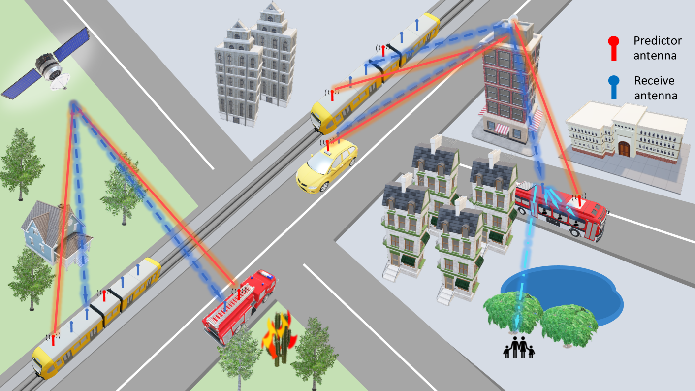
As an alternative method to combat the channel aging phenomenon in MRs, [5] proposed the predictor antenna (PA) concept. In such a system, two groups of antennas are deployed on the roof of a vehicle, in which the PAs mounted in the front are used for predicting the channel for the receive antennas aligned behind the PAs once the RAs reach the same position several time slots later (see Fig. 1). With a TDD (T: Time) setup, at time , the PA sends the access point pilots (The PA concept is applicable in both TDD and FDD systems [8, 9]). Then, the access point, either the BS or the satellite/ high altitude platform (HAP), estimates the uplink (UL) channel, uses that to obtain an estimate of the downlink (DL) channel based on channel reciprocity, and with appropriate transmission parameter adaptation sends the data to the RA at time . Here, depends on the processing time at the access point, and parameter adaptation may include power, rate and/or BF update. In this way, as shown in Table I, compared to Kalman predictor, the presence of the PA increases the prediction horizon considerably, where with the parameter settings of Table I and a 5 ms processing delay at the BS, for different speeds/frequencies the PA gives 5 times higher supported speed. Also, prediction horizons up to three times the wavelengths are achievable with PA-based system at 2.68 GHz and a velocity of 45-50 km/h, while Kalman prediction supports around 0.1-0.3 wavelengths [5].
Following [5], different testbed implementations and analytical studies were developed for PAs. Particularly, [1] performed system-level simulations on PA-MR concept and revealed that VPL is effectively reduced. From antenna design perspective, [10] verified the effect of coupling compensation, and the PA methods were practically tested in Dresden, Germany. Other testbed-based studies include [6] and [11] extending the PA concept to MIMO case and showing the power of channel interpolations. Also, channel measurement studies [9] verified that PA can be used in both TDD and FDD systems. Finally, analytical modeling of PAs were developed in [8], and various performance enhancements schemes were proposed.
In this paper, we demonstrate the potential benefits as well as the practical challenges of PAs. We compare the performance of PA-based schemes with different non-PA alternative methods, in terms of end-to-end (E2E) throughput and prediction accuracy. The results are presented for both urban (Section II) and rural areas (Section III) where the MR is served by a terrestrial BS and a satellite/HAP, respectively. Also, we study the throughput in the presence of both blockage and tree foliage, and verify the effect of the BF, estimation error and CSIT quantization on the system performance (Section III). Finally, revisiting the field trial results on PAs, we highlight the previous and current standardization attempts on (moving) relays as well as the key points which should be addressed before the MRs and, potentially, PAs can be used in practice (Section IV).
Our results show that the PA concept is an attractive candidate technique for improving the backhauling performance of MRs. Particularly, with typical parameter settings/vehicle speeds and a single PA, the implementation of the PA can increase the backhaul throughput of the MR, compared to open-loop systems, by ; the result that can be boosted significantly by massive MIMO-based BF.
| Fixed delay = 5 ms | Fixed frequency = 2.68 GHz | ||||||||
|
|
||||||||
| Frequency (GHz) | PA | Kalman | Delay (ms) | PA | Kalman | ||||
| 1 | 324 | 65 | 1 | 604 | 120 | ||||
| 2.68 | 120 | 24 | 3 | 201 | 40 | ||||
| 4 | 81 | 16 | 5 | 120 | 24 | ||||
| 6 | 54 | 11 | 8 | 75 | 15 | ||||
II The Potential of PA; Urab Area Study
With vehicular speeds, the distance traveled during the typical control-loop delays of, say, ms, is in the order of meter or less. Hence, the moving direction can be well assumed to be almost linear. Also, as verified experimentally in [10], during such a period the vehicle experiences an essentially stationary electromagnetic standing wave pattern. Then, if the RA ends up in the same position, it will experience the same radio environment, and the CSIT will be almost perfect (the effect of CSIT quantization and estimation error due to noisy channel measurements are studied in the following). Nevertheless, the CSIT quality and, as a result, the overall performance may be deteriorated by spatial mismatch; if the RA ends up in a different point from where the PA estimated the channel, due to, e.g., the processing delay at the BS is not the same as the time that the RA needs to arrive to the same point as the PA, the CSIT will be imperfect. To address this problem, without increasing the number of pilots, one can consider two different methods:
-
•
Adaptive-delay setup: Knowing the vehicle speed, the transmission delay can be dynamically adapted, as a function of the antennas distance and vehicle speed, such that the RA receives the data at the same point as the PA sending pilots. In this case, there is potentially no spatial mismatch, at the cost of extra transmission delay. However, the delay adaptation method is applicable only for a range of vehicle speeds limited by the access point’s minimum required processing delay. Also, cellular technologies only allow for a limited transmission time interval granularity and, in practice, there would be a residual mispointing.
-
•
Nonadaptive-delay setup: As an alternative approach, one can always consider the access point’s minimum processing delay. This method, which is more appropriate for slotted communication systems, is at the cost of possible spatial mismatch. However, we can use the spatial correlations to determine the appropriate data transmission parameters for different positions surrounding the point where the PA was sending the pilots, and adapt the transmission parameters based on imperfect CSIT [8].
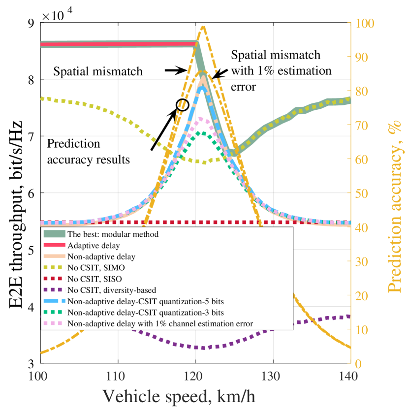
Considering an urban area with a BS serving the vehicle, Fig. 2 compares the performance of the adaptive- and nonadaptive-delay PA systems with a number of alternative schemes including:
-
•
A benchmark SISO (S: single) scheme with single antenna on the vehicle and no CSIT at the BS.
-
•
A SIMO setup with no CSIT at the BS. Here, both the PA and the RA receive the data simultaneously from the BS, and the receiver tries decoding by maximum ratio combining (MRC) of the received signals.
-
•
A diversity-based scheme where, considering a SISO setup, the same signal is transmitted in two spectrum resources, and an MRC-based receiver is used for signal decoding.
The results are presented for spatially-correlated Rayleigh-fading conditions where, using the Jakes’ correlation model and assuming uniform angular spectrum, one can model the channel around the PA with the same procedure as in [8, Eq. (37)-(43)].
As the metric of interest, we consider the normalized prediction accuracy and E2E throughput in bits per second (bps), which is defined as the average number of correctly decoded information bits per the E2E transmission delay. The E2E transmission delay is given by the transmission delay plus the possible processing delay at the BS, i.e., . In the adaptive-delay PA setup the processing delay is dynamically determined based on the vehicle speed, while with a non-adaptive delay PA system is set to the minimum processing delay of the BS. In the other benchmark schemes, we have , as the BS is provided with no CSIT. Finally, please note that in our simulations, for each scheme, rate optimization have been utilized to maximize the E2E throughput. In simulations, we use a 5G frame structure with 14 symbols per slot, and the total time duration is 1 ms. Here, and also in Fig. 5, the results are presented in bit/s/Hz, i.e., in normalized case. The results can be easily scaled depending on the considered bandwidth.
Figure 2 demonstrates the potential of PA system where, for a broad range of vehicle speeds, the highest E2E throughput is achieved by the PA method, compared to the benchmark schemes. However, there is not a single method providing the highest throughput, and a modular setup of different schemes guarantees the highest throughput for different speeds; Delay-adaptive PA method gives the maximum throughput at low speeds, limited by the BS minimum required processing delay. At moderate speeds, exploiting the spatial correlation and using the nonadaptive-delay PA method leads to the highest throughput. Finally, at high speeds, where the spatial correlation between the initial position of the PA and the final position of the RA decreases, using both antennas for simultaneous data reception with no CSIT at the BS gives the maximum E2E throughput.
Along with spatial mismatch, different factors such as channel estimation/quantization error and mismatch of the UL and DL channels may affect the system performance. Figure 2 gives the throughput for both cases with channel estimation errors (due to noisy measurements) and quantization errors. As shown, for different parameter settings, estimation/quantization errors affect the throughput slightly, and the PA-based scheme improves the throughput, compared to benchmark schemes.
We concentrate on E2E throughput, as it enables us to consider the cost of CSIT acquisition, and compare different schemes fairly. Alternatively, as in [5, 6, 10, 11, 9], one can consider the estimation error/prediction accuracy. Figure 2 shows the prediction accuracy of the PA setup for different speeds. As demonstrated, the prediction accuracy results are in harmony with the E2E throughput results, and the effect of estimation/quantization errors on the throughput is almost negligible for a broad range of vehicle speeds.
Note that Fig. 2 studies the system performance for the worst-case scenario with only two antennas on the vehicle, one antenna at the BS and no BF. As explained in the following, with a large number of antennas the relative cost of allocating one antenna for only channel estimation decreases, and the benefit of PA method increases.
II-A MASSIVE MIMO BF IN MULTI-PATH PROPAGATION ENVIRONMENT
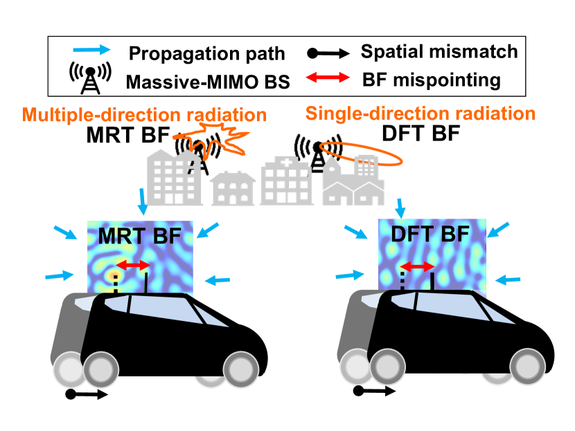
CSIT-based massive MIMO adaptive BF schemes, e.g., maximum ratio transmission (MRT) and zero-forcing (ZF), suffer from BF mispointing as a result of spatial mismatch, and could benefit from the PA [6]. Figure 3 illustrates BF mispointing for the MRT and ZF BF in an NLoS (N: non) multi-path propagation scenario that is likely to be encountered in an urban environment. When MRT BF is used in a Rayleigh two-dimensional propagation environment, the BF pattern is close to a Bessel function, with side lobes every half wave length. Hence, even a small spatial mismatch implies a strong degradation in the received power. As illustrated in Fig. 3, discrete Fourier transform (DFT)-based BF also suffers from BF mispointing, but in a less severe manner. Indeed, on one side, as illustrated in Fig. 3, MRT BF adapts to each individual path and is very sensitive to CSIT error, whereas, DFT BF forms a large beam towards a single direction, and is therefore less sensitive to CSIT error.
Figure 4 shows the cumulative distribution function (CDF) of the received power at the vehicle side, with antennas at the BS, various prediction schemes (ideal prediction and without prediction, i.e., with a spatial mismatch), different CSIT-based BF schemes (MRT and DFT) and a scheme without CSIT (where all antennas transmit the same signal). A typical 5G link at 3.5 GHz carrier frequency, with velocities of 100 km/h and 10 km/h as well as a delay of 5 ms, corresponding to a spatial mismatch of around 1.6 and 0.16 wavelength, is considered. As illustrated in Fig. 4, for all schemes, the performance degradation due to spatial mismatch is in an order of magnitude.
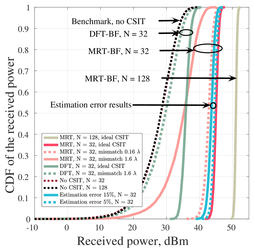
Thanks to the PA, BF can be used to mitigate the spatial mispointing problem [6], thus improving the received power of the network, especially when the network is highly loaded with numerous moving cars or high speed trains. However, as explained, PA alone may suffer from residual spatial mismatch when the velocity, the PA spacing and the delay do not match. In this case, a prediction with zero residual spatial mismatch is obtained by filtering and interpolating multiple measurements that suffer from residual spatial mismatch. Recently, such schemes, with low complexity and intended for implementation and in-line running on real BS, have been designed [9]. Finally, experimental measurements [11], with a car, a 64-antenna MIMO BS in NLoS urban environment and various PA spacing values, have shown that the received power for the MRT BF with PA-based prediction is close to that obtained by ideal prediction. It is also shown that both MRT and ZF BF-based received powers are improved by an order of magnitude with PA-based prediction, even when the PA spacing, i.e., the spatial mismatch to be compensated, is as large as 3 wavelengths. Based on these studies, we can conclude that the gap between ideal prediction and the curves with spatial mismatch, illustrated in Fig. 4, can be filled by PA-based BF. Finally, in harmony with Fig. 2, Fig. 4 shows that, with multiple antennas and BF, the system performance is slightly affected by channel estimation error.
III Rural Area Study: PA on a Train with Many Wagons
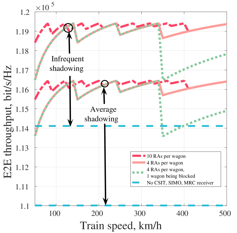
The PA concept can be well applied in rural areas where, e.g., the high-speed train is served by a satellite in geostationary orbit or an HAP having high geographical coverage. Particularly, the presence of multiple wagons gives the chance to implement different channel learning and PA-RA pairing methods, and compensate for, e.g., blockage and channel aging. As an illustrative example, Fig. 5 shows the E2E throughput of the last wagon of a train with ten wagons, each equipped with a PA and RAs. Here, best-combination scheme is used where, with an adaptive-delay method, the information of all PAs is collected, and for each wagon the PA-RA pair with the lowest transmission delay/highest CSIT accuracy is peaked for data transmission to the selected RA.
To evaluate the effect of tree foliage, the results are presented for different shadowed Rice models for land mobile satellite channels with average and infrequent light shadowings [12, Table. III] which model the cases with moderate and low tree densities, respectively. Also, the figure verifies the robustness of the PA system to blockage where the throughput is presented for the cases with one of the wagons, the ninth wagon, being fully blocked.
The figure shows that, for a broad range of train speeds, the PA-based scheme can boost the E2E throughput, compared to the baseline approach with a SIMO setup using MRC receiver, and the relative performance gain of the PA method increases with tree foliage. Also, the implementation of the PA with proper antenna pairing leads to relatively low throughput variation at different speeds, and the throughput variation decreases with the number of RAs per wagon. Finally, although blockage leads to throughput drop in certain ranges of speed, still the PA-based transmission is useful combating the channel aging phenomenon. Consequently, the PA provides the in-vehicle UEs with almost constant QoS in different environments/speeds. Finally, while Fig. 5 presents the simplest case with a single antenna at the satellite, with multiple antennas/wagons one can exploit the location information and dynamically adapt the BF to reduce the effect of blockage/foliage even further.
IV Towards Practical PAs; Standardization and Testbed Evaluations
To validate the PA concept, various field trials have been performed:
-
•
In 2014, we performed a field trial of the PA system in Dresden, Germany [10]. The testbed was based on installing two in-line thin monopole antennas on the roof of a vehicle running at around 50 km/h with orthogonal frequency division multiplexing (OFDM), a bandwidth of 20 MHz and carrier frequency 2.68 GHz. From the field trials, the cross-correlation between the received signals of the PA and RA is observed to remain high (), after coupling compensation, for at least 3 times the wavelength in both LoS and NLoS scenarios.
-
•
In 2018, our drive tests in Stuttgart, Germany, with a massive MIMO setup operating at 2.18 GHz showed that, at low/moderate speeds, the complex OFDM DL channels can be well predicted with an accuracy that enables MRT BF with close to ideal BF gain for NLoS channels [11].
-
•
In 2018, [9] performed a testbed-based study in Dresden, Germany, with vehicle speed of 25-50 km/h at 2.53 GHz for both LoS and NLoS channels. The experiments validated the correlation-based analytical model, and proved that prediction accuracy of around -13 to -7 dB is sufficient to support various transmission schemes such as precoding and spatial multiplexing.
These testbed results verify the usefulness of the PA concept in MRs. However, to be practically implemented, MR standardization should be first specified.
In 5G New Radio (NR), relay-based communication is mainly followed under the concept of integrated access and backhaul (IAB), introduced by the 3rd Generation Partnership Project (3GPP) in Release 16. The goal of IAB is to provide NR radio-access technology not only for the access link between the UEs and the network, but also for wireless backhauling in a, possibly, multi-hop, fashion.
IAB-like functionality based on Long-Term Evolution (LTE) was introduced in 3GPP Release 10 [13]. Also, there was a study-item on mobile relay mainly focusing on high-speed trains [14]. However, LTE-based wireless backhaul was not extensively used, primarily due to LTE being constrained to sub-6 GHz spectrum which is often seen as too valuable spectrum for backhauling. In contrast, NR, in particular IAB, can operate also in millimeter wave (mmWave) spectrum above 10 GHz.
In general, the IAB architecture follows the centralized unit (CU)/ distributed unit (DU) split of gNB, as introduced in 3GPP Release 15. Here, a gNB consists of two functionally different modules:
-
•
A CU as the unit hosting the upper layers of the gNB protocol stack.
-
•
One or multiple DUs hosting medium access control (MAC), radio link control (RLC), and physical-layer protocols.
To enable wireless backhaul, the IAB architecture considers two different network nodes. The IAB-donor hosts CU and DU functionalities, and connects to the core network via non-IAB, e.g., fiber backhaul. The DU of the donor may serve UEs, as a conventional gNB, but will also serve wirelessly connected IAB nodes.
IAB nodes rely on NR for wireless backhauling, and consist of DU functionality that serves UEs and, possibly, child IAB nodes in case of multi-hop IAB. Also, an IAB node consists of a mobile terminal (MT) functionality which connects to the DU of the higher node, called the parent of the IAB node.
In most aspects, the IAB link, i.e., the link between MT part of an IAB and the DU part of its parent node operates as a conventional gNB-UE link. As a consequence, the NR physical, MAC, and RLC layers have limited extensions regarding the IAB, with a major focus on the coordination of the IAB-node MT and DUs. For more details on IAB, see [15].
In principle, the MT part of an IAB node may contain full UE functionality, including mobility functionality. Also, it is likely to have multiple antennas at the DU and MT with advanced antenna/signal processing techniques. Thus, the PA concept would be possible to implement, once the IAB-based MR is installed. However, in practice the current IAB standardization impose strong constraints on the mobility of the IAB nodes:
-
•
Full IAB node mobility would imply that the DU of an IAB node could move between different CUs, a functionality not supported by the currently standardized CU/DU split.
-
•
IAB-node mobility between different parent nodes, even if they are located under the same donor, that is, the same CU, would imply that routing tables within the IAB nodes would have to be dynamically updated, a functionality not supported by the current IAB specifications.
-
•
From an architecture point-of-view, nothing prevents IAB-node mobility as long as the IAB node remains under the same parent node. However, this would imply that the cells created by the IAB node would not be stationary, something which would lead to many challenges in terms of cell planning and radio-resource management.
Also, inter-node measurement, power control and interference management are challenging topics in mobile IAB. Thus, in practice the current IAB specifications are limited to essentially stationary IAB nodes.
In the early discussions on enhancements to IAB in 3GPP Release 17, the introduction of support for mobile IAB was extensively discussed. However, mainly due to time limitations, it was eventually decided not to include this in the scope of the IAB enhancements pursued in Release 17. It is not unlikely though that the introduction of mobile IAB nodes will be further brought up again and considered for future NR releases. In that case, we need to handle different challenges including the CSIT accuracy given the sensitivity of the mmWave-based narrow BF to inaccurate CSIT/BF mismatch. Here, along with other methods, the PA concept may be a useful method potentially in combination with other alternative schemes.
V Conclusions
We presented the potentials of the PA setup to improve the CSIT accuracy in high-speed vehicles. Presenting the field trials on PA systems as well as the previous/ongoing standardization attempts on (moving) relays, we discussed the key challenges that need to be solved before the MR and, potentially, the PA setup, can be practically used. The simulation and testbed results show that the PA concept is a potential solution to support future adaptive antenna systems for fast-moving vehicles. However, there is still room for further theoretical and experimental research, including testbed experiments at high speeds/carrier frequencies as well as practical comparisons/combinations of various alternative methods.
Acknowledgement
This work was supported in part by VINNOVA (Swedish Government Agency for Innovation Systems) within the VINN Excellence Center ChaseOn. Thank Yigeng Zhang from University of Huston for the help on illustrations.
References
- [1] Y. Sui et al., “Moving cells: A promising solution to boost performance for vehicular users,” IEEE Commun. Mag., vol. 51, no. 6, pp. 62–68, Jun. 2013.
- [2] S. Jaffry et al., “A comprehensive survey on moving networks,” Mar. 2020, available: https://arxiv.org/pdf/2003.09979.
- [3] 3GPP TR 36.913, “Requirements for Further Advancements for Evolved Universal Terrestrial Radio Access (EUTRA) (LTE-Advanced),” Edinburgh, GB, Sept. 2014, available: https://www.3gpp.org/ftp/Specs/archive/36_series/36.913.
- [4] J. Wu and P. Fan, “A survey on high mobility wireless communications: Challenges, opportunities and solutions,” IEEE Access, vol. 4, pp. 450–476, Jan. 2016.
- [5] M. Sternad et al., “Using predictor antennas for long-range prediction of fast fading for moving relays,” in Proc. IEEE WCNCW, Paris, France, Apr. 2012, pp. 253–257.
- [6] D.-T. Phan-Huy et al., “Making 5G adaptive antennas work for very fast moving vehicles,” IEEE Intell. Transp. Syst. Mag., vol. 7, no. 2, pp. 71–84, Apr. 2015.
- [7] L. S. Muppirisetty et al., “Spatial wireless channel prediction under location uncertainty,” IEEE Trans. on Wireless Commun., vol. 15, no. 2, pp. 1031–1044, Feb. 2016.
- [8] H. Guo et al., “A semi-linear approximation of the first-order Marcum -function with application to predictor antenna systems,” IEEE Open J. Commun. Soc., vol. 2, pp. 273–286, Feb. 2021.
- [9] J. Björsell et al., “Predictor antennas in action,” in Proc. IEEE PIMRC, Montreal, Quebec, Canada, Oct. 2017, pp. 1–7.
- [10] N. Jamaly et al., “Analysis and measurement of multiple antenna systems for fading channel prediction in moving relays,” in Proc. IEEE EuCAP, The Hague, The Netherlands, Apr. 2014, pp. 2015–2019.
- [11] D.-T. Phan-Huy et al., “Adaptive massive MIMO for fast moving connected vehicles: It will work with predictor antennas!” in Proc. IEEE WSA, Bochum, Germany, Mar. 2018, pp. 1–8.
- [12] A. Abdi et al., “A new simple model for land mobile satellite channels: First- and second-order statistics,” IEEE Trans. Wireless Commun., vol. 2, no. 3, pp. 519–528, May 2003.
- [13] 3GPP, “Overview of 3GPP Release 10 V0.2.1,” Jun. 2014, available: https://www.3gpp.org/ftp/Information/WORK_PLAN/Description_Releases/.
- [14] 3GPP TR 36.836, “Evolved Universal Terrestrial Radio Access (E-UTRA); Study on mobile relay,” Sophia-Antipolis , FR, Jun. 2014, available: https://www.3gpp.org/ftp/Specs/archive/36_series/36.836/.
- [15] C. Madapatha et al., “Integrated access and backhaul networks: Current status and potentials,” IEEE Open J. Commun. Soc., vol. 1, pp. 1374–1389, Sept. 2020.
| Hao Guo [S’17] (hao.guo@chalmers.se) is currently pursuing his PhD degree with Department of Electrical Engineering, Chalmers, Sweden. |
| Behrooz Makki [M’19, SM’19] works as Senior Researcher in Ericsson Research, Sweden. |
| Dinh-Thuy Phan-Huy currently works as Project Manager and Senior R&D Engineer on wireless communications at Orange, France. |
| Erik Dahlman is currently Senior Expert in Radio Access Technologies within Ericsson Research. |
| Mohamed-Slim Alouini [S’94, M’98, SM’03, F’09] is a Professor of Electrical Engineering in King Abdullah University of Science and Technology, Thuwal, Saudi Arabia. |
| Tommy Svensson [S’98, M’03, SM’10] is a Professor in Communication Systems at Chalmers University of Technology, Sweden. |