Further author information: (Send correspondence to T.E.H.)
T.E.H.: E-mail: tom.essinger-hileman@nasa.gov, Telephone: +1 301 286 3693
Optical Design of the EXperiment for Cryogenic Large-Aperture Intensity Mapping (EXCLAIM)
Abstract
This work describes the optical design of the EXperiment for Cryogenic Large-Aperture Intensity Mapping (EXCLAIM). EXCLAIM is a balloon-borne telescope that will measure integrated line emission from carbon monoxide (CO) at redshifts and ionized carbon ([CII]) at redshifts to probe star formation over cosmic time in cross-correlation with galaxy redshift surveys. The EXCLAIM instrument will observe at frequencies of – GHz using six microfabricated silicon integrated spectrometers with spectral resolving power coupled to kinetic inductance detectors (KIDs). A completely cryogenic telescope cooled to a temperature below 5 K provides low-background observations between narrow atmospheric lines in the stratosphere. Off-axis reflective optics use a -cm primary mirror to provide full-width at half-maximum (FWHM) resolution at the center of the EXCLAIM band over a field of view of . Illumination of the K cold stop combined with blackened baffling at multiple places in the optical system ensures low ( dB) edge illumination of the primary to minimize spill onto warmer elements at the top of the dewar.
keywords:
Intensity mapping, cosmology, star formation1 INTRODUCTION
Star formation reached a peak at a redshift and has subsequently declined despite the continued growth of dark matter haloes[1, 2]. Galactic feedback mechanisms are commonly thought to be the cause of this decline, but further observations are required to disentangle the effects. Line intensity mapping (LIM), in which integrated line emission is mapped at low angular resolution, offers a complementary approach to traditional galaxy surveys with several advantages. LIM creates a map of all emission in a given line free from selection bias. Furthermore, the low angular resolution required enables large survey areas to be efficiently mapped with modest requirements on the aperture size. Simulations[3] show tensions with measurements of CO in individual galaxies, motivating a blind, complete survey over a large area.
The EXperiment for Cryogenic Large-Aperture Intensity Mapping (EXCLAIM) is a balloon-borne cryogenic telescope that will measure diffuse emission from several carbon monoxide (CO) rotational lines ( GHz) for at redshifts and singly-ionized carbon ([CII]) in the µm ( THz) line at redshifts . The EXCLAIM survey will consist of a 320 deg2 extragalactic (EG) survey and several deg2 galactic plane (GP) survey regions. The GP survey will map CO(4-3) and neutral carbon ([CI]). The [CI] survey will assess the CO-H2 ratio to inform the higher-redshift survey, as [CI] traces H2 in regions where CO is photodissociated[4, 5]. The EG survey will be cross-correlated with galaxies and quasars in the Baryon Oscillation Spectroscopic Survey (BOSS) [6] to map EXCLAIM observations in redshift space.
EXCLAIM consists of a completely cryogenic telescope in an open liquid-helium bucket dewar with a cold inner volume approximately 1.5 m in diameter and 2.0 m deep. At target float altitudes above km, the ambient pressure of less than Torr pumps on the helium bath, lowering its temperature below its superfluid transition to approximately 1.7 K. Superfluid helium pumps demonstrated on the ARCADE2 and PIPER payloads [7, 8, 9] efficiently cool the full optical chain to below 5 K.
The EXCLAIM optics consist of a two-mirror, off-axis Gregorian telescope with a 90-cm parabolic primary mirror and a 10-cm parabolic secondary mirror. A folding flat between the primary and secondary allows the telescope to fit within the dewar volume. Baffling around the intermediate focus controls stray light and houses an aerogel scattering filter for rejection of IR radiation. [10] The rays are collimated after the secondary mirror and pass through a meta-material anti-reflection (AR) coated silicon vacuum window into the receiver cryostat. The receiver houses additional stray-light baffling, aerogel scattering and band-defining metal-mesh filters, [11] an AR-coated silicon lens, [12] and six integrated silicon spectrometers (µ-Spec). [13, 14, 15]
The µ-Spec spectrometers combine all the elements of a traditional diffraction-grating spectrometer in a compact package using planar transmission lines on a silicon chip. The grating is replaced by a niobium microstrip delay line network that launches signals into a 2D parallel-plate waveguide region with emitting and receiving feeds arranged in a Rowland configuration. EXCLAIM will operate at the second grating order selected by an on-chip filter along with the free-space band-defining filters. A set of 355 microwave kinetic inductance detectors (MKIDs) made from 20-nm-thick aluminum (Al) half-wave resonators will detect the signal. A dipole slot antenna coupled to a hyper-hemispherical AR-coated silicon lenslet forms the spectrometer beam and couples the light to the on-chip circuitry. The combination of quasi-optical metal-mesh filters, on-chip filters, and spectrometer design defines the EXCLAIM observing band of – GHz. The MKID arrays for the six spectrometers use a microwave multiplexing readout scheme with heritage from The Next Generation Balloon-borne Large Aperture Submillimeter Telescope (BLAST-TNG) [16] and the Far Infrared Observatory Mounted on a Pointed Balloon (OLIMPO). [17]
The EXCLAIM gondola design, attitude determination and control system, and flight electronics are based on those of PIPER with modest modifications and improvements. EXCLAIM will observe at constant elevation with scans in azimuth between and wide to map strips on the sky. A primary target is Sloan Stripe 82; however, the details of the scan strategy will depend upon the availability of sources for a given flight location and time of year.
For more information on the EXCLAIM mission, see Cataldo et al. in these proceedings. [18] For details of the spectrometer design and fabrication, see Mirzaei et al. in these proceedings. [19] This paper is organized as follows. Section 2 describes the optical design requirements, system layout, and key optical components. Section 3 describes the performance of the optical system as modeled with ray-tracing software. Section 4 describes physical-optics analysis of diffraction in the system. We conclude in Section 5.
 |
2 OPTICAL DESIGN
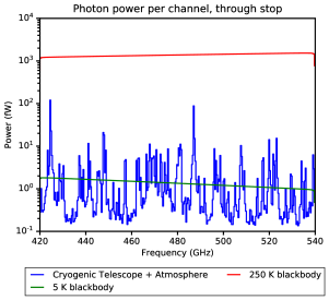
The EXCLAIM optical design is unique in several ways. As EXCLAIM is not taking an instantaneous image and the map is filled in by multiple observations with different detectors in each pixel, the optical design has relatively loose requirements on optical aberrations. There are, however, very stringent requirements on total excess loading on the detectors, since modest spill onto warm elements will significantly degrade performance in the darkest spectral channels. As shown in Figure. 1, even modest illumination at the dB level of a 300 K surface is comparable to the power in the darkest channels. The EXCLAIM optical design aims to limit stray light through the overall system architecture, combined with baffling in key places.
In this section, we describe the requirements on the optical system that flow down from EXCLAIM science and mission objectives (Section 2.1); give an overview of the optical design that meets those requirements (Section 2.2); and describe the design of key optical components, including the silicon superfluid-tight receiver window, silicon lens, coupling to the spectrometer wafer via a dipole antenna and hyper-hemispherical silicon lenslet, IR-blocking aerogel scattering filters, metal-mesh band-defining filters, and in-flight calibration source (Section 2.3).
 |
2.1 Requirements Overview
The EXCLAIM optical design needs to satisfy a number of mechanical, optical, cryogenic, and integration and test (I&T) requirements. Primary requirements on the optical design are:
-
1.
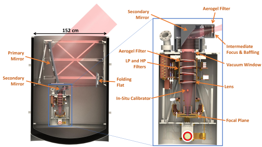
The telescope shall fit within a cylindrical volume approximately 1.2 m in diameter and 1.5 m deep. This corresponds to the usable volume within a bucket dewar sized such that the payload fits within mass limits set by balloon lift capabilities of kg. The bucket dewar is the same size as has been demonstrated for the PIPER payload. See Figure 2 for more details on the payload mechanical design.
-
2.
The angular resolution shall be to allow measurement of physical scales down to approximately 200 kpc (modes h/Mpc).
-
3.
The design shall maintain total root-mean-squared (RMS) wave front error (WFE) below 0.075 waves at the center of the band, 480 GHz. This corresponds to a Strehl ratio greater than 0.80.
-
4.
The instantaneous field of view (FOV) of the telescope shall be between and . This allows efficient mapping of the target observation areas given the angular resolution.
-
5.
Excess loading from stray light on each KID shall be below the expected power in the darkest spectrometer channels, fW defined at the receiver cold stop, to ensure nearly background limited performance across the band.
-
6.
The optical design shall provide for a collimated region within the receiver volume with a 3:1 aspect ratio for effective magnetic shielding, as the KIDs are susceptible to magnetic fields.
-
7.
The telescope shall operate at K to ensure that loading from the reflective optics, assuming a pessimistic 10% total emissivity, does not exceed 0.1 fW, requiring that warm alignment translates to alignment upon cooling.
-
8.
The receiver shall be placed vertically under the primary mirror to allow the receiver to be tested in a liquid helium dewar prior to integration with the telescope and to allow the telescope to be aligned separately from and before integration with the receiver.
-
9.
The design shall provide a means for rapid optical modulation in the event that the stability of the detector data is not sufficient. MKIDs and the associated readout system can have excess low-frequency, or , noise due to two-level systems that would lead to striping in the maps. The primary science signal band for EXCLAIM is approximately 5–25 Hz, based on the current scan strategy. This requirement ensures that rapid modulation could be implemented if required after laboratory testing or the engineering flight to mitigate excess noise.
These primary requirements lead to a series of derived requirements on the optical design. Key derived requirements are:
-
10.
The telescope shall have a physical aperture of 90 cm and projected aperture of 76 cm. This fulfills the angular resolution requirement while fitting within the allowable volume and allowing under-illumination of the primary mirror to reduce ambient-temperature spill. See Sec. 4 for more discussion of angular resolution given realistic Gaussian beam truncation.
-
11.
The reflective telescope shall be to stay within the allowable volume, while producing a collimated region inside the receiver of reasonable diameter, cm, to provide the required 3:1 aspect ratio for magnetic shielding.
-
12.
The receiver shall house a 1.8 K cold aperture stop that truncates the beams from the on-chip spectrometer lenslets at dB at all frequencies within the EXCLAIM band to maintain low edge illumination on the primary mirror for stray light reduction. Given the lenslet beam width (See Sec. 2.2), this requires that the system be after the silicon lens.
-
13.
Stray light spill onto ambient temperature ( K) surfaces, including those behind the primary mirror, around the dewar aperture, and the balloon, shall be less than dB. This ensures that excess loading from warm spill stays below 0.1 fW.
Though not a strict requirement, the design also attempted to reduce the potential for optical cavities to create fringing within the EXCLAIM band and multiple images of objects on the sky from ghosting. As a spectrometer, EXCLAIM is more prone to this than broadband imaging experiments. Given the design spectral resolving power, , at the center of the EXCLAIM band, GHz, each MKID channel is sensitive to a bandwidth of approximately GHz. This leads to a coherence length, , of approximately cm, which is on the order of the size of the optics tube within the receiver. To mitigate possible cavities formed within the receiver optics tube, the silicon lens and filters were tilted with respect to the chief ray by and , respectively. Different tilt directions were used for each optical element to further reduce cavity modes.
 |
 |
2.2 Optical Layout
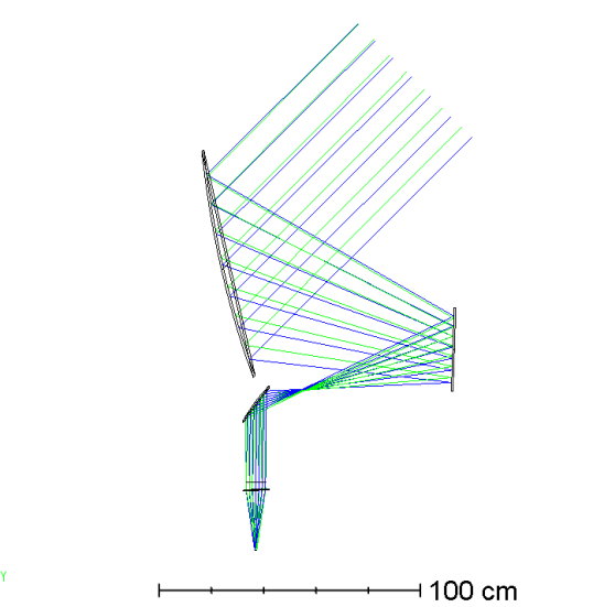
To meet the requirements set out above, the EXCLAIM optical design shown in Figure 3 uses a large, 90 cm, off-axis parabolic primary mirror that is 76 cm in projection. This primary mirror is highly under-illuminated to reduce beam spill around the edges of the primary, which could fall onto warm surfaces. The effective focal length of the primary mirror is set to 155 cm to allow the rays to come to an intermediate focus within the dewar volume on the way to the secondary mirror. A folding flat 30 cm in diameter redirects the rays so that the optical system can fit within the dewar and to allow the secondary mirror to be under the primary mirror, as required by the integration and test sequence.
A more complicated design including a hyperbolic mirror in place of the folding flat in a Mizugutch-Dragone configuration [20, 21] was initially considered; however, the performance of the simpler design outlined here was found to be sufficient given the reasonably loose requirements on optical aberrations and cross polarization for EXCLAIM. Having a folding flat in place of a shaped mirror significantly reduces system complexity and mirror fabrication costs with modest loss of optical quality.
The intermediate focus is important for stray-light control, allowing the secondary mirror and receiver window to be placed entirely within a baffled enclosure. In this enclosure and in the receiver optics tube, baffle rings are blackened with Epotek 377 epoxy loaded with silica and graphite powders. [22] The thickness of this coating is chosen to be 2 mm to provide a balance between absorption at frequencies below the EXCLAIM band and mass of the coating. The thickness and shape of the coating will be controlled using molds following the procedures described in Ref. 23. This intermediate focus also provides a natural place for a chopper if rapid optical modulation is deemed necessary after an engineering flight.
After the intermediate focus, a parabolic secondary mirror with an effective focal length of 19.5 cm collimates the beam as it enters the receiver through the AR-coated silicon vacuum window. The collimated region is 23 cm long and serves multiple purposes. The initial driving requirement was to allow for magnetic shielding with a favorable 3:1 aspect ratio to be placed around the spectrometers, as the MKIDs are sensitive to magnetic fields. Note that the magnetic shield diameter of 14 cm is necessarily larger than the diameter of the optical baffling to allow room for mechanical clearance between the magnetic shield and copper optics tube, as well as for mounting flanges for the lens, filters, and the optics tube as a whole. This means that the collimated region and focal length of the lens, at 24 cm, combine to provide an approximately 3:1 aspect ratio for the magnetic shielding. Optically, the collimated region affords an extended baffled section for stray light control and a natural location for free-space filters.
 |
 |
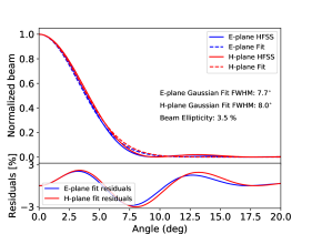
The receiver houses a blackened 7.6 cm cold aperture stop and a plano-convex silicon lens with a focal length of 24 cm to couple light onto the hyper-hemispherical lenslets of the spectrometers. As noted above, the silicon lens is tilted by to reduce cavity modes and ghosting within the receiver. The planar surface of the tilted lens faces toward the focal plane. The 4-mm diameter lenslets provide an approximately Gaussian beam with a full-width at half maximum (FWHM) of (mean of E- and H-plane) at the center of the EXCLAIM band, 470 GHz. The corresponding dB angle for the beams at that frequency is full angle. At the low-frequency edge of the band at 420 GHz, the FWHM and dB half angle are and , respectively. As the beams are broadest for the lowest frequency within the band, requiring the cold stop to truncate at dB across the full band translates into a 7.6-cm cold stop diameter given the 24-cm lens focal length, leading to an optical speed of at the focal plane.
The six 4.0-mm diameter lenslets are equally spaced around a 9.0-mm circle (4.5 mm between neighboring lenslets) to give adequate space for the supporting silicon wafer and reasonable fabrication tolerances on the copper detector package. With the lenslet separation set, the field of view of the telescope is determined by the plate scale, which specifies the ratio between distance within the focal plane and angular separation on the sky. For this design, the plate scale is given by , where , , and are the focal lengths of the primary mirror, secondary mirror, and lens, respectively. Given the values above, the plate scale of the system is /mm, corresponding to a field of view for the 9-mm focal plane of , well within the range of Requirement 4.
2.3 Optical Components
In this section we briefly summarize key design and manufacturing considerations for EXCLAIM optical components, including the aluminum primary, folding flat, and secondary mirrors; the silicon lens and receiver window, band-defining and IR blocking filters, and in-situ calibrator.
2.3.1 Mirror Manufacturing
The primary, folding flat, and secondary mirrors will be computer numerical control (CNC) machined out of monolithic pieces of aluminum. The surface figure of the mirrors is required to be within 25 µm of nominal, corresponding to RMS phase error of 0.020 waves at 470 GHz. It is assumed that the folding flat will be able to achieve considerably better surface figure. The contributions of the primary and secondary mirror surface figure errors add together in quadrature to give total mirror surface figure wavefront error less than 0.028 waves.
The RMS surface roughness of the mirrors is required to be below 2 µm, so that scattering from the mirrors onto warm surfaces stays well below dB. A surface roughness gives rise to a gain degradation factor of
| (1) |
where is the RMS surface roughness and is the observing wavelength. Requiring this term to be below dB corresponds to an RMS surface finish of approximately 0.4 µm. The required surface figure is achievable if care is taken in the CNC machining process. Post-machining polishing will bring the surface finish within the requirement.
2.3.2 Silicon Lens and Receiver Window
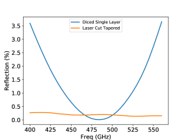
The receiver houses both a lens and a vacuum window, which will be made of silicon with a metamaterial AR coating. A single-layer AR coating produced by a custom dicing saw on a computer-controlled XY gantry system [12] provides sufficient performance over the EXCLAIM band, as shown in Fig. 5; however, a tapered profile created using a laser-cutting system provides higher performance and is the baseline for EXCLAIM. Silicon lenses have been demonstrated on a number of instruments. EXCLAIM will be demonstrating a superfluid silicon vacuum window for the first time. The window must maintain high in-band transmission, while providing a superfluid-tight vacuum seal. PIPER has previously demonstrated a quartz window with a superfluid-tight indium seal and a polytetrafluoroethylene AR coating; [24] however, the measured quartz loss at EXCLAIM frequencies is significant, leading to the choice of silicon as an alternative.
 |
 |
2.3.3 Filters
EXCLAIM requires free-space filters for IR rejection and band definition. Two IR-blocking filters will be used in the EXCLAIM system, one near the intermediate focus and the other as the first element after the vacuum window within the receiver volume. These IR blocking filters will be composed of diamond scattering particles embedded in a polyimide aerogel substrate with low index of refraction and low loss. [10] Particle size and density will be tuned to produce a lowpass filter with a cutoff frequency THz.
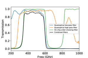
Two free-space filters for band definition will be placed between the IR blocking filter and the aperture stop within the receiver optics tube and will be composed of a heat-pressed stack of metal-mesh filters on polypropylene film with dielectric spacers. [11] A combination of a highpass and lowpass filter, used in conjunction with an order-sorting filter on the spectrometer wafer, will reject radiation immediately above and below the EXCLAIM band. Fig. 5 shows the modeled transmission spectra of the band-defining filters along with the resultant composite spectrum.
2.3.4 In-Situ Calibrator
The EXCLAIM receiver will incorporate an in-situ calibration source for in-flight characterization of spectrometer response, uniformity, and time-varying responsivity. The source is a reverse bolometer of similar design to that used by the Herschel SPIRE instrument. [25] It consists of a sapphire square with an integrated heater thermally isolated from the bath stage using nylon threads. This reverse bolometer is mounted in a copper ring and placed within a bead-blasted integrating cavity. A small aperture in the cavity couples power out to the spectrometers. The calibrator is placed just below and outside the lens to couple into the sidelobes of the on-chip spectrometer lenslet beams.
3 DESIGN PERFORMANCE, TOLERANCING, AND ALIGNMENT
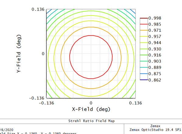
The EXCLAIM optical design was laid out and optimized using Zemax OpticStudio in sequential mode. Once the basic design described in Sec. 2 was determined, it was optimized to minimize WFE, allowing the lens radius and thickness to vary. Calculations of Strehl ratio, or equivalently WFE, across the field of view verify that the design is diffraction limited for all frequencies, as shown in Fig. 3.
After an optimized design was found, Zemax was used to place tolerances on important parameters in the system, including the lens radius and thickness, mirror tilts, and mirror displacements. As laid out in the requirements in Sec. 2.1, the target WFE is 0.075 waves. The target mirror surface figures for the primary and secondary mirrors contribute 0.020 waves of WFE each, for a combined 0.028 waves when added in quadrature. This leaves 0.070 waves of WFE allowable for the misaligned system, where the nominal design has WFE of 0.040 waves. After an initial sensitivity analysis, in which individual parameters were varied alone to determine good ranges to explore for each, Monte Carlo (MC) simulations were performed using Zemax to determine tolerances for the system as a whole varying all parameters together.
Tilts of the mirrors are the most tightly constrained, requiring that they be controlled to , , and for the primary, folding flat, and secondary mirrors, respectively. Given the relative sizes of the mirrors, these tolerances require similar tolerances on the positions of the mount points on each mirror of approximately 0.5 mm each. Mirror decenter tolerances were found to be mm or greater, while tolerances on the relative distances of mirrors was found to be mm or greater.
The telescope is held within the dewar using a stainless steel truss frame. The aluminum primary mirror and folding flat are attached to this frame via hexapod mounts with built-in flexures to allow for differential contraction upon cooling. Turnbuckles on each of the hexapod mounting arms provide precise control of the mirror positions. The aluminum secondary mirror is hard-mounted from the stainles steel receiver lid with flexures to allow for differential contraction. A precision pinning arrangement will align the secondary mirror to the silicon lens and focal plane. Alignment points on the exterior of the secondary mirror allow the receiver and secondary mirror assembly to be aligned to the folding flat via a hexapod mount.
A coordinate measuring arm111Romer Absolute Arm, Model 7520, Hexagon Metrology, Oceanside, CA. will measure relative positions of the mirrors warm. These positions will be compared with a model of the telescope as it will be when warm and slightly misaligned. Small adjustments will be made, followed by additional measurements. This process will be repeated iteratively until the mirrors are measured to be within the required tolerances. Based on experience in aligning the PIPER mirrors with the same coordinate-measurement arm and a nearly identical alignment scheme, it is expected that the mirrors can be brought to within 0.2 mm of the target positions, well within the requirements set by WFE.
4 DIFFRACTION ANALYSIS
Due to the stringent requirements on warm beam spill for EXCLAIM, a diffractive analysis of the optics is being carried out to complement the ray-tracing results presented above. The primary goal of the diffraction analysis is to ensure that the spill on the primary is less than -40dB, thereby minimizing loading from warm sources on the instrument. The diffraction analysis is performed in two steps: (i) on-axis quasi-optics simulation via POPPY222This research made use of POPPY, an open-source optical propagation Python package originally developed for the James Webb Space Telescope project [26]., and (ii) off-axis physical optics simulation via CST. The former is computationally inexpensive and allows us to simulate the full baffling assembly, though it does not include off-axis effects from the mirrors. The CST simulation offers a complementary approach – it allows us to accurately simulate the off-axis mirrors though it is computationally expensive and difficult to account for baffles and the lens. At the time of this writing, we have achieved satisfactory results for the POPPY simulation, while the CST simulation work is on-going.
| Element | Distance from cold stop | Parameters |
|---|---|---|
| Lens aperture | 0 | FWHM cm |
| Cold stop | 0 | cm |
| Optics tube baffles | (0.89, 1.78, 2.67, 5.46, 6.35, 7.24, 10.03, 10.92, 11.81) cm | cm |
| Secondary mirror | 33.06 cm | cm |
| Intermediate focus baffle | 54.00 cm | cm |
| Primary mirror | 188.06 cm | cm |
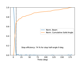
The simulation parameters for the POPPY simulation are shown in Table 1. The simulation begins at the lens, at which the wavefront has a Gaussian profile truncated by the cold stop. This is a good approximation, as shown in Fig. 4. The mirrors are simulated as lenses with corresponding focal lengths and the baffles are simulated as pupils. We used the Fresnel Optical System setting to obtain the results shown in Figure 6. Four different cases are shown: (i) baffles at both the intermediate focus (IF) and optics tube (OT); (ii) IF baffle only; (iii) optics tube baffles only; (iv) no baffles. These simulations were performed for an optical frequency of GHz.
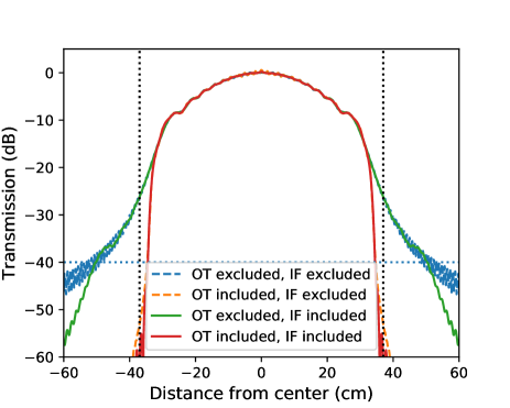

As shown in Figure 6, the optics tube baffling is necessary and sufficient to reduce spill at the edge of the primary to well below the -40 dB target. In the case that OT and IF baffles are included, the main lobe is nearly Gaussian with a FWHM 22.4 cm and edge taper dB. The edge taper is defined as the absolute value of the primary illumination at the effective mirror radius of 38 cm, and it is heavily suppressed through the inclusion of OT baffles as shown in the left figure. The baffle at the intermediate focus smooths out diffraction wiggles in the main lobe, as shown in the right figure, which we attribute to the truncation of the beam at the cold stop. In either case, the diffraction wiggles in the main lobe disappear when propagating to the far field.
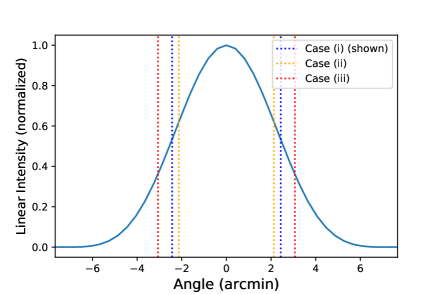
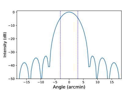
The far-field beam for the fully-baffled POPPY simulation is shown in Figure 7. The two plots show a slice through the beam center in a linear scale (left) and logarithmic scale (right). The far-field calculations were performed for three different cases for the illumination on the primary mirror: (i) full POPPY simulation; (ii) Gaussian with 22.4 cm, truncated at the primary effective radius; (iii) Gaussian with dB.
In Case (i) we calculated the far-field pattern by Fourier Transforming the primary illumination shown in Figure 6, resulting in = 4.33 arcmin. For the latter two cases we calculated using the phenomenological relation[27]
| (2) |
Equation 2 assumes a Gaussian primary mirror, truncated at an edge taper of , where is the wavelength and is the effective diameter of the primary. For Cases (ii) and (iii) the truncated Gaussian estimates were 3.78 arcmin and 5.44 arcmin, respectively. was underestimated in Case (ii) by 0.55 arcmin because the mirror edges were over-illuminated, roughly corresponding to the exclusion of OT baffles. was overestimated in Case (iii) because the bright main lobe was underestimated by only considering the heavily-suppressed edge illumination. While the analytical estimates were both incorrect, the fully-simulated beam did exhibit the expected linear scaling with wavelength to a precision of one part in , demonstrating strong agreement with the scaling in Equation 2. Comparing Cases (i) and (ii) we see only a modest increase in , demonstrating that the inclusion of OT baffles accomplishes our goal of decreasing the spill on the primary, while not causing an unacceptable degradation in the far-field performance of the telescope.
The CST simulations have not yet been completed at the time of this writing. Our strategy is to utilize CST Microwave Studio Suite’s Integral Equation Solver, which is ideal for computations featuring reflective mirrors with diameters much larger than the simulated wavelength, as for the EXCLAIM reflectors. The parameters for the CST simulation are identical to those in Table 1 except for the baffles. We are investigating ways to include the effects of both the optics tube and IF baffles. The primary computational limit is system memory requirements; we estimate a computation at 100 GHz calculated at the location of the primary mirror would require 2.4 TB of RAM. We have successfully simulated the full set of mirrors at lower frequencies and find that memory requirements scale roughly as frequency squared. We are currently investigating high-throughput computing resources to complete the high-frequency simulations.
 |
 |
5 CONCLUSION
The optical design for the EXCLAIM instrument has been described. This design meets all requirements placed on it by the science goals and overall mission architecture. The catadioptric system employs a 90 cm parabolic primary mirror, 30 cm folding flat, and 10 cm parabolic secondary mirror, along with a 10 cm silicon lens inside the receiver optics tube, to provide FWHM resolution in the center of the EXCLAIM band at 480 GHz over a field of view.
The EXCLAIM mission design requires tight control over spill onto warm surfaces at the top of the dewar where light enters the cryogenic telescope. Particular care has been taken in the design to ensure that spill onto warm elements remains below dB. This is achieved with absorptive baffling in the receiver optics tube and around the intermediate focus between the primary and secondary mirrors. Initial results using analytic POPPY simulations in an on-axis analog system suggest that the current system meets this requirement with significant margin. Simulations of the off-axis system using CST Microwave to verify this are on-going.
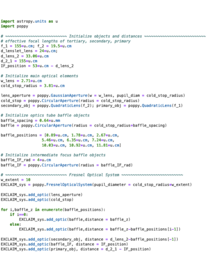
Appendix A POPPY Source Code
Figure 8 shows source code initializing the FresnelOpticalSystem class corresponding to the EXCLAIM POPPY simulation.
References
- [1] Walter, F., Carilli, C., Neeleman, M., Decarli, R., Popping, G., Somerville, R. S., Aravena, M., Bertoldi, F., Boogaard, L., Cox, P., da Cunha, E., Magnelli, B., Obreschkow, D., Riechers, D., Rix, H.-W., Smail, I., Weiss, A., Assef, R. J., Bauer, F., Bouwens, R., Contini, T., Cortes, P. C., Daddi, E., Diaz-Santos, T., González-López, J., Hennawi, J., Hodge, J. A., Inami, H., Ivison, R., Oesch, P., Sargent, M., van der Werf, P., Wagg, J., and Yung, L. Y. A., “The Evolution of the Baryons Associated with Galaxies Averaged over Cosmic Time and Space,” Astrophys. J. 902, 111 (Oct. 2020).
- [2] Madau, P. and Dickinson, M., “Cosmic Star-Formation History,” Annu. Rev. Astron. Astrophys. 52, 415–486 (2014).
- [3] Popping, G., Pillepich, A., Somerville, R. S., Decarli, R., Walter, F., Aravena, M., Carilli, C., Cox, P., Nelson, D., Riechers, D., Weiss, A., Boogaard, L., Bouwens, R., Contini, T., Cortes, P. C., da Cunha, E., Daddi, E., Díaz-Santos, T., Diemer, B., González-López, J., Hernquist, L., Ivison, R., Le Fèvre, O., Marinacci, F., Rix, H.-W., Swinbank, M., Vogelsberger, M., van der Werf, P., Wagg, J., and Yung, L. Y. A., “The ALMA Spectroscopic Survey in the HUDF: the Molecular Gas Content of Galaxies and Tensions with IllustrisTNG and the Santa Cruz SAM,” Astrophys. J. 882, 137 (Sept. 2019).
- [4] Burton, M. G., Ashley, M. C. B., Braiding, C., Freeman, M., Kulesa, C., Wolfire, M. G., Hollenbach, D. J., Rowell, G., and Lau, J., “Extended Carbon Line Emission in the Galaxy: Searching for Dark Molecular Gas along the G328 Sightline,” Astrophysical Journal 811, 13 (Sept. 2015).
- [5] Wolfire, M. G., Hollenbach, D., and McKee, C. F., “The Dark Molecular Gas,” Astrophysical Journal 716, 1191–1207 (June 2010).
- [6] eBOSS Collaboration, Alam, S., Aubert, M., Avila, S., Balland, C., Bautista, J. E., Bershady, M. A., Bizyaev, D., Blanton, M. R., Bolton, A. S., Bovy, J., Brinkmann, J., Brownstein, J. R., Burtin, E., Chabanier, S., Chapman, M. J., Choi, P. D., Chuang, C.-H., Comparat, J., Cuceu, A., Dawson, K. S., de la Macorra, A., de la Torre, S., de Mattia, A., de Sainte Agathe, V., du Mas des Bourboux, H., Escoffier, S., Etourneau, T., Farr, J., Font-Ribera, A., Frinchaboy, P. M., Fromenteau, S., Gil-Marín, H., Gonzalez-Morales, A. X., Gonzalez-Perez, V., Grabowski, K., Guy, J., Hawken, A. J., Hou, J., Kong, H., Klaene, M., Kneib, J.-P., Le Goff, J.-M., Lin, S., Long, D., Lyke, B. W., Cousinou, M.-C., Martini, P., Masters, K., Mohammad, F. G., Moon, J., Mueller, E.-M., Munõz-Gutieŕrez, A., Myers, A. D., Nadathur, S., Neveux, R., Newman, J. A., Noterdaeme, P., Oravetz, A., Oravetz, D., Palanque-Delabrouille, N., Pan, K., Parker, James, I., Paviot, R., Percival, W. J., Peŕez-Rafols, I., Petitjean, P., Pieri, M. M., Prakash, A., Raichoor, A., Ravoux, C., Rezaie, M., Rich, J., Ross, A. J., Rossi, G., Ruggeri, R., Ruhlmann-Kleider, V., Sańchez, A. G., Sańchez, F. J., Sańchez-Gallego, J. R., Sayres, C., Schneider, D. P., Seo, H.-J., Shafieloo, A., Slosar, A., Smith, A., Stermer, J., Tamone, A., Tinker, J. L., Tojeiro, R., Vargas-Magaña, M., Variu, A., Wang, Y., Weaver, B. A., Weijmans, A.-M., Yeche, C., Zarrouk, P., Zhao, C., Zhao, G.-B., and Zheng, Z., “The Completed SDSS-IV extended Baryon Oscillation Spectroscopic Survey: Cosmological Implications from two Decades of Spectroscopic Surveys at the Apache Point observatory,” arXiv e-prints , arXiv:2007.08991 (July 2020).
- [7] Singal, J., Fixsen, D. J., Kogut, A., Levin, S., Limon, M., Lubin, P., Mirel, P., Seiffert, M., Villela, T., Wollack, E., and Wuensche, C. A., “The ARCADE 2 Instrument,” The Astrophysical Journal 730, 138 (Apr. 2011).
- [8] Gandilo, N. N., Ade, P. A. R., Benford, D., Bennett, C. L., Chuss, D. T., Dotson, J. L., Eimer, J. R., Fixsen, D. J., Halpern, M., Hilton, G., Hinshaw, G. F., Irwin, K., Jhabvala, C., Kimball, M., Kogut, A., Lowe, L., McMahon, J. J., Miller, T. M., Mirel, P., Moseley, S. H., Pawlyk, S., Rodriguez, S., Sharp, E., Shirron, P., Staguhn, J. G., Sullivan, D. F., Switzer, E. R., Taraschi, P., Tucker, C. E., and Wollack, E. J., “The Primordial Inflation Polarization Explorer (PIPER),” in [Millimeter, Submillimeter, and Far-Infrared Detectors and Instrumentation for Astronomy VIII ], Holland, W. S. and Zmuidzinas, J., eds., Society of Photo-Optical Instrumentation Engineers (SPIE) Conference Series 9914, 99141J (July 2016).
- [9] Kogut, A. et al., “Superfluid Liquid Helium Control for the Primordial Inflation Polarization Explorer Balloon Payload,” In Prep. (2020).
- [10] Essinger-Hileman, T., Bennett, C. L., Corbett, L., Guo, H., Helson, K., Marriage, T., Meador, M. A. B., Rostem, K., and Wollack, E. J., “Aerogel scattering filters for cosmic microwave background observations,” Applied Optics 59, 5439 (June 2020).
- [11] Ade, P. A. R., Pisano, G., Tucker, C., and Weaver, S., “A review of metal mesh filters,” in [Society of Photo-Optical Instrumentation Engineers (SPIE) Conference Series ], Zmuidzinas, J., Holland, W. S., Withington, S., and Duncan, W. D., eds., Society of Photo-Optical Instrumentation Engineers (SPIE) Conference Series 6275, 62750U (June 2006).
- [12] Datta, R., Munson, C. D., Niemack, M. D., McMahon, J. J., Britton, J., Wollack, E. J., Beall, J., Devlin, M. J., Fowler, J., Gallardo, P., Hubmayr, J., Irwin, K., Newburgh, L., Nibarger, J. P., Page, L., Quijada, M. A., Schmitt, B. L., Staggs, S. T., Thornton, R., and Zhang, L., “Large-aperture wide-bandwidth antireflection-coated silicon lenses for millimeter wavelengths,” Applied Optics 52, 8747 (Dec. 2013).
- [13] Cataldo, G., Hsieh, W.-T., Huang, W.-C., Moseley, S. H., Stevenson, T. R., and Wollack, E. J., “Micro-Spec: an ultracompact, high-sensitivity spectrometer for far-infrared and submillimeter astronomy,” Applied Optics 53, 1094 (Feb. 2014).
- [14] Noroozian, O., Barrentine, E., Brown, A., Cataldo, G., Ehsan, N., Hsieh, W.-T., Stevenson, T., U-yen, K., Wollack, E., and Moseley, S. H., “µ-spec: An efficient compact integrated spectrometer for submillimeter astrophysics,” in [26th International Symposium on Space Terahertz Technology ], (2015).
- [15] Barrentine, E. M., Cataldo, G., Brown, A. D., Ehsan, N., Noroozian, O., Stevenson, T. R., U-Yen, K., Wollack, E. J., and Moseley, S. H., “Design and performance of a high resolution -spec: an integrated sub-millimeter spectrometer,” in [Millimeter, Submillimeter, and Far-Infrared Detectors and Instrumentation for Astronomy VIII ], Holland, W. S. and Zmuidzinas, J., eds., Society of Photo-Optical Instrumentation Engineers (SPIE) Conference Series 9914, 99143O (July 2016).
- [16] Lourie, N. P., Angilé, F. E., Ashton, P. C., Catanzaro, B., Devlin, M. J., Dicker, S., Didier, J., Dober, B., Fissel, L. M., Galitzki, N., Gordon, S., Klein, J., Lowe, I., Mauskopf, P., Nati, F., Novak, G., Romualdez, L. J., Soler, J. D., and Williams, P. A., “Design and characterization of a balloon-borne diffraction-limited submillimeter telescope platform for BLAST-TNG,” in [Ground-based and Airborne Telescopes VII ], Marshall, H. K. and Spyromilio, J., eds., Society of Photo-Optical Instrumentation Engineers (SPIE) Conference Series 10700, 1070022 (July 2018).
- [17] Presta, G., Ade, P. A. R., Battistelli, E. S., Castellano, M. G., Colantoni, I., Columbro, F., Coppolecchia, A., D’ Alessandro, G., de Bernardis, P., Gordon, S., Lamagna, L., Masi, S., Mauskopf, P., Paiella, A., Pettinari, G., Piacentini, F., Pisano, G., and Tucker, C., “The first flight of the OLIMPO experiment: instrument performance,” in [Journal of Physics Conference Series ], Journal of Physics Conference Series 1548, 012018 (May 2020).
- [18] Cataldo, G. et al., “Overview and status of EXCLAIM, the experiment for cryogenic large-aperture intensity mapping,” in [Millimeter, Submillimeter, and Far-Infrared Detectors and Instrumentation for Astronomy X ], International Society for Optics and Photonics (2020).
- [19] Mirzaei, M. et al., “µ-Spec Spectrometers for the EXCLAIM Instrument,” in [Millimeter, Submillimeter, and Far-Infrared Detectors and Instrumentation for Astronomy X ], International Society for Optics and Photonics (2020).
- [20] Dragone, C. and Hogg, D. C., “The radiation pattern and impedance of offset and symmetrical near-field Cassegrainian and Gregorian antennas.,” IEEE Transactions on Antennas and Propagation 22, 472–475 (Jan. 1974).
- [21] Mizugutch, Y., Akagawa, M., and Yokoi, H., “Offset Dual Reflector Antenna,” in [IEEE International Symposium on Antennas and Propagation Digest ], 2–5 (Jan. 1976).
- [22] Chuss, D. T., Rostem, K., Wollack, E. J., Berman, L., Colazo, F., DeGeorge, M., Helson, K., and Sagliocca, M., “A cryogenic thermal source for detector array characterization,” Review of Scientific Instruments 88, 104501 (Oct. 2017).
- [23] Sharp, E. H., Benford, D. J., Fixsen, D. J., Moseley, S. H., Staguhn, J. G., and Wollack, E. J., “Stray light suppression in the Goddard IRAM 2-Millimeter Observer (GISMO),” in [Millimeter, Submillimeter, and Far-Infrared Detectors and Instrumentation for Astronomy VI ], Holland, W. S. and Zmuidzinas, J., eds., Society of Photo-Optical Instrumentation Engineers (SPIE) Conference Series 8452, 84523I (Sept. 2012).
- [24] Datta, R. et al., “Anti-reflection-coated vacuum window for the PIPER balloon-borne instrument,” Submitted to Rev. Sci. Inst. (2020).
- [25] Pisano, G., Hargrave, P., Griffin, M., Collins, P., Beeman, J., and Hermoso, R., “Thermal illuminators for far-infrared and submillimeter astronomical instruments,” Applied Optics 44, 3208–3217 (June 2005).
- [26] Perrin, M. D., Soummer, R., Elliott, E. M., Lallo, M. D., and Sivaramakrishnan, A., “Simulating point spread functions for the james webb space telescope with webbpsf,” in [Space Telescopes and Instrumentation 2012: Optical, Infrared, and Millimeter Wave ], 8442, 84423D, International Society for Optics and Photonics (2012).
- [27] Goldsmith, P. F., “Radiation patterns of circular apertures with gaussian illumination,” International Journal of Infrared and Millimeter Waves 8(7), 771–781 (1987).