Benjamin Ramtoula, Adam Caccavale, Giovanni Beltrame, and Mac Schwager
11institutetext:
University of Oxford, Oxford, UK
11email: benjamin@robots.ox.ac.uk
22institutetext: Stanford University, Stanford, USA
22email: {awc11,schwager}@stanford.edu
33institutetext: Polytechnique Montréal, Montréal, Canada
33email: giovanni.beltrame@polymtl.ca
MSL-RAPTOR: A 6DoF Relative Pose Tracker for Onboard Robotic Perception
Abstract
Determining the relative position and orientation of objects in an environment is a fundamental building block for a wide range of robotics applications. To accomplish this task efficiently in practical settings, a method must be fast, use common sensors, and generalize easily to new objects and environments. We present MSL-RAPTOR, a two-stage algorithm for tracking a rigid body with a monocular camera. The image is first processed by an efficient neural network-based front-end to detect new objects and track 2D bounding boxes between frames. The class label and bounding box is passed to the back-end that updates the object’s pose using an unscented Kalman filter (UKF). The measurement posterior is fed back to the 2D tracker to improve robustness. The object’s class is identified so a class-specific UKF can be used if custom dynamics and constraints are known. Adapting to track the pose of new classes only requires providing a trained 2D object detector or labeled 2D bounding box data, as well as the approximate size of the objects. The performance of MSL-RAPTOR is first verified on the NOCS-REAL275 dataset, achieving results comparable to RGB-D approaches despite not using depth measurements. When tracking a flying drone from onboard another drone, it outperforms the fastest comparable method in speed by a factor of 3, while giving lower translation and rotation median errors by 66% and 23% respectively.
keywords:
Perception, Aerial Robots, Machine Learning1 Introduction
For a robot to intelligently interact with its environment, it must quickly and accurately determine the relative position and orientation of neighboring robots, people, vehicles, and a variety of other static and dynamic obstacles in the scene. From drone racing [1] to pedestrian avoidance [2], tasks relying on such estimates are numerous and are essential to creating truly autonomous robots. Regardless, the ability to track the six Degree of Freedom (6DoF) relative pose of a dynamic object in real-time, with onboard sensing and computation, is largely beyond the reach of existing robot perception frameworks. To fill this need, we propose Monocular Sequential Lightweight Rotation And Position Tracking On-Robots (MSL-RAPTOR), a lightweight, general-purpose robot perception module for tracking the 6DoF relative pose of a dynamic object using only an onboard monocular camera. MSL-RAPTOR performs similarly to state-of-the-art approaches relying on more sensors (e.g. depth) and greater computation capability.
Existing methods for 6DoF relative pose estimation from vision can be divided into model-based, deep learning-based, and hybrid methods. Existing model-based approaches rely on matching the view of an object to a database of templates or visual features. These methods are limited in the face of scenes with low textures or changing conditions, and cannot be used when prior 3D models of objects are not available [3, 4]. Deep learning methods such as PoseCNN [5] and LieNets [6] overcome these challenges by directly estimating the relative pose from images, learning this inverse map from a large corpus of training data. Hybrid approaches combine elements of deep neural networks and model-based methods. For example, BB8 [7], SSD-6D [8], and SingleShotPose [9] (SSP) all use deep neural networks to estimate the 2D projections of the 3D bounding box encompassing the object. These projections are then used to solve the Perspective-n-Point (PnP) problem to obtain a pose estimate [10]. Another hybrid method, NOCS [11], estimates pose using pixel correspondences and depth data with category-level canonical representations. However, the above deep and hybrid methods ignore temporal correlations among multiple frames to aid in tracking objects. In contrast, 6-PACK [12] leverages temporal consistency by learning to represent objects using keypoints that are matched between frames. While these methods present impressive pose estimation performance, they are either too slow, too computationally demanding, or require too much prior model knowledge to be used for practical onboard relative pose perception for resource-limited robots.
These same limitations apply to the many pose tracking approaches developed for self-driving cars, for which tracking methods represent a key component of the system [2]. These rely on the use of rich sensors and/or advanced computational capabilities to achieve online performance and often assume planar constraints since they deal solely with land-based objects (e.g. pedestrians, other vehicles), hence are only SE(2) trackers with 3DoF (e.g. [13, 14]).
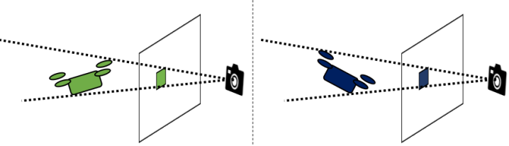
Contribution. With the requirements for onboard robotic perception in mind, we propose MSL-RAPTOR, which seeks to combine the best aspects of deep learning-based and model-based perception paradigms. MSL-RAPTOR takes raw image data with a dual deep neural network architecture on the front-end to produce and track an angled 2D bounding box around an object in the scene. A single 2D bounding box is not enough information to determine the object’s pose (see Fig. 2), so this semantically labeled bounding box is passed to a model-based Unscented Kalman Filter (UKF) [17, 18] back-end to fuse measurements across time and produce a Bayesian relative pose estimate for the object. The deep front-end uses a YOLOv3 network [15], retrained with robot-specific object classes, for initial object detection and labeling, together with a SiamMask network [16] for quickly tracking the 2D object bounding box from frame to frame once it has been detected. The 2D bounding box corners and semantic object labels (e.g., “person”, “UAV”, “car”, “tree”) are then passed to the UKF back-end. The back-end uses the bounding box corners as pseudo-measurements, which are fused over time to infer the full 6DoF relative pose of the object. The UKF propagates the target’s motion with a label-specific motion model (since people, cars, and UAVs all move differently). We then close the loop between back-end and front-end with a re-detection trigger. If the Mahalanobis distance between the measurement and its posterior is above a threshold or if the pose estimate is too close to the edge of the field of view (judged using the z-test based on its covariance), the target is considered lost, and we re-trigger the YOLO target detection on the front-end. With this framework, we can track an object through occlusions and temporary absences from the field of view. MSL-RAPTOR currently assumes a single object in the scene, but the extension to multiple objects (and classes) is straightforward.
We demonstrate MSL-RAPTOR running on a Jetson TX2 onboard a standard quadrotor UAV platform while tracking another UAV at 8.7 frames per second. This is 3 times faster than the fastest comparable state-of-the-art method, SSP [9], and produces pose estimates with 66% and 23% lower translation and rotation median errors, respectively. We also compare performance with several state-of-the-art deep learning methods for 6DoF pose tracking using a depth camera. We show on standard datasets that MSL-RAPTOR performs similarly to these existing methods despite only using a monocular camera with no depth information.
2 Problem Formulation
We consider the scenario where a computationally-limited mobile robotic agent with a calibrated monocular camera needs to identify and track the relative pose of a dynamic object from a series of RGB images . The state at time is where is 3D position, is linear velocity, is the orientation as a quaternion, and is angular velocity. The position and orientation component of this state can be represented as the object pose . Henceforth the time superscripts will be dropped for notational convenience unless they are needed for clarity.
The object has a span in 3D space that can be approximated with a sparse set of points , most commonly the corners of its 3D bounding box which we use by default. Additionally, each object has a corresponding class label (e.g. drone, bottle, etc) denoted . Each class of object has an associated dynamics model used to propagate the components of the state in the UKF back-end: . By default a simple constant velocity model is used, but more sophisticated class-specific models may be provided. In general we assume no knowledge of the tracked object’s control input.
When processing an image, the 2D projections of the object’s points onto the image are enclosed in the minimum-area angled bounding box: where and are the column and row of the box center, and are the box width and height, and is the box angle from the horizontal image axis. If instead an axis-aligned bounding box is produced (i.e. ), it is denoted (Fig. 2). The distribution of estimates over states and measurements are both modeled as Gaussians, and respectively. When evaluating the consistency of a measurement with our prior estimate, we use the Mahalanobis distance defined as:
| (1) |
3 Algorithm
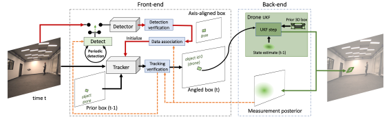
The architecture of our approach is illustrated in Fig. 1. The front-end has two components for processing the images: a detector and a visual tracker. The detector can identify all objects in an image and their class labels, but is slower and only generates axis-aligned bounding boxes. The tracker is faster and produces angled bounding boxes, but requires an accurate 2D bounding box from the previous timestep. The back-end relies on a class-specific UKF, taking in an angled bounding box measurement from the front-end to produce pose estimates. For each image, the decision to use the tracker vs. detection is determined by the consistency of the new bounding box measurement with the measurement posterior generated by the back-end’s UKF.
3.1 Object detection
Upon receiving an image , the angled bounding boxes must be extracted. If the object has not been previously located, or if re-detection has been triggered, a pre-trained, out-of-the-box object detector outputs the axis-aligned bounding box and class label for each visible object : .
Only bounding boxes for the class of interest are considered, and if multiple boxes are found, the one closest to our current estimate as measured by Eqn. 1 is used. If our estimate’s uncertainty is too high, then the box with highest confidence is chosen. This axis-aligned bounding box is then used to initialize the visual tracker (Sec. 3.2) which produces an angled bounding box measurement . This, along with the class label from the detector, serves to initialize the UKF (Sec. 3.3). Because the filter requires an initial pose estimate, the initial 6D pose is roughly approximated assuming the width, height, and roll are aligned with the 2D bounding box. This is a poor assumption in general, but the robustness of the filter will compensate for the initialization error. As the class of the object is also identified, class-based initialization rules can also be used (e.g. mugs are usually upright).
3.2 Visual tracking
Once an object has been detected and the associated tracker and UKF are initialized, MSL-RAPTOR’s front-end only relies on the tracker to provide measurements to the UKF. The tracker is an object-agnostic method, which produces an angled bounding box measurement given the previous bounding box and a new image .
When a new image is available, the tracker generates an angled bounding box that serves as an observation for the UKF predicting the object’s pose (Sec. 3.3).
Aside from the speed benefit, we use a visual tracking method that produces angled bounding boxes that are more informative measurements than the axis-aligned boxes as illustrated in Fig. 2. While the angle is still not sufficient to uniquely determine an object’s pose, it reduces the set of poses that would result in the given measurement which improves tracking performance.
3.3 Unscented Kalman Filter
To estimate pose from a series of angled bounding box measurements, we use a class-dependent unscented Kalman filter. Probabilistic filters like the UKF consist of a prediction and update step. During prediction, the state is propagated forward using the object dynamics, and the expected measurement from the resulting anticipated state is calculated. In the update step, the difference between the predicted and actual measurement is used to adjust the state estimate and uncertainty. A typical output of a UKF is the mean and covariance of the state, but as part of the update process, the measurement mean and covariance are also calculated. These are passed to the front-end for determining whether to trigger re-detection (Sec. 3.4).
The prediction step of the UKF relies on a dynamics model, which can optionally depend on the object tracked. The MSL-RAPTOR framework gives access to a class label for each object, enabling the use of class-specific dynamics if available, or a simple constant velocity model if not. For systems without significant inertial effects this is a good approximation, otherwise, we rely on the robustness of the filter to correct for the modeling error.
To predict the expected measurement associated to a pose, the knowledge of the 3D points representing the tracked object is used. The vertices are projected into the image plane using the known camera intrinsic matrix and the estimate of the object’s pose in the camera frame [19]. The minimum area rectangle that encloses these projected pixels is the predicted measurement .
A UKF is chosen over alternatives such as an EKF or PF due to its efficient handling of the non-linearities inherent in the system. The PF’s natural ability to track multiple-hypothesis potentially could allow it to better determine poses that best explain the series of bounding box measurements, but empirical testing showed the computational requirements of this method to be too high to run onboard.
3.4 Updating the tracked objects
Occlusions, objects leaving the field of view, and poor measurements (e.g. due to light reflections) can all cause tracking failures that lead to inaccurate bounding boxes. No assumptions are made regarding these scenarios. To address these challenges, detection is triggered periodically to identify and locate when the object has become unoccluded or has entered the image. This has the advantage of compensating for any drift or errors that might occur in the visual tracking. The front-end’s verification mechanisms can also trigger detection to correct for uncertain measurements.
3.4.1 Bounding Box Verification
Detected measurements
Detection returns both the bounding box and the class label of the object. This can be used to filter detections by class and to set class-specific rejection conditions for the measurement that can help prevent false-positive matches. For example, an aspect ratio condition can be set so that a bounding box is valid only if it is in a valid class-specific aspect-ratio range:
where the thresholds and can be determined from the typical geometry of the class. Additionally, a threshold on the minimum distance to the edge of the image can prevent bad measurements due to truncated bounding boxes:
Tracker measurements
At each iteration of the UKF, anticipated measurements are predicted for a range of perturbations about the current state estimate. From this set of possible measurements, a mean and covariance representing the distribution of observations is calculated. The Mahalanobis distance (Eqn. 1) is compared against a threshold to evaluate the likelihood of new measurements. If a mismatch between the state estimate of the back-end and the new measurement is detected, this could indicate drift in the tracker or some other failure, and detection is triggered.
Additionally, to ensure the object is fully in view, -tests using the diagonal values of are performed at each edge. The results are compared with a threshold.
The probabilistic thresholds in this section can be chosen from the quantiles of the chi-squared distribution and normal distribution, respectively. When the test fails, the system switches into detection mode to either confirm it should stop tracking the object, or to correct its tracked bounding box.
4 Experimental Results
4.1 Implementation choices
For our experiments we implement MSL-RAPTOR with YOLOv3 [15] from Ultralytics [20] for our front-end’s object detector. We chose YOLOv3 due to its ubiquity, speed, and demonstrated ability to detect a range of objects. To support the objects used in our experiments, we retrain it on the COCO dataset mixed with a custom dataset containing images of a flying quadrotor, which leads to 81 supported object categories. For our visual tracker, we rely on the implementation of SiamMask [16] provided by the authors, which is object-agnostic and therefore does not require retraining. We chose SiamMask for its speed, ability to produce angled bounding boxes, and impressive tracking performance. We use the provided weights trained on the VOT dataset [21].
4.2 Evaluation on the NOCS-REAL275 dataset
We begin by evaluating MSL-RAPTOR on the NOCS-REAL275 dataset [11] to answer a fundamental question about the method: can the algorithm track pose accurately for a range of objects? In all, the dataset contains seven training videos and six testing videos from a camera moving in different scenes. The scenes contain objects with class labels in {bowl, mug, can, bottle, laptop, and camera}. We tune our class-specific UKF parameters using the training set and present the results evaluated on the testing set. Similarly to the baseline methods, we do not penalize orientation errors about axes of symmetry for the can, bowl, and bottle classes.
Implementation details
Our re-detection and verification mechanisms presented in 3.4 serve to make the tracking robust to occlusions and to handle objects exiting and entering the frame. However, sequences of the dataset are relatively short and mostly maintain all objects in the field of view. Moreover, the datasets used to train our detector did not contain instances of all the classes appearing in the scenes, and the training set from NOCS-REAL275 would not be general enough to train the detector to properly detect new instances of objects in the testing set. For these reasons, we disable the probabilistic detection and verification mechanisms for evaluation on this dataset and rely only on visual tracking in the front-end. This is a conservative approach as violations of these assumptions will reduce our performance.
To replace MSL-RAPTOR’s filter initialization, which is based on the disabled detection, the same method is used as the baselines [12, 22, 23]. For a given object , random uniform translation noise of up to 4cm is added to the ground truth initial pose . From this initialized pose, the first bounding box is calculated using the UKF’s measurement prediction function . We add uniformly sampled noise of up to 5% of the width and height of the box to its row and width, and its column and height respectively. With this first bounding box, the visual tracker will generate future measurements.
For objects in the dataset with shapes not well approximated by a 3D bounding box (bowl, laptop, mug), we add additional vertices to restrict the volume. For example, 12 points are used instead of 8 for the laptop, resulting in an “L” shape when viewed from the side. For mugs and bowls, extra points allow a tighter fit around curved rims. Using these refined volumes reduces the mismatch between predicted and observed measurements in the UKF, which can lead to incorrect adjustments of the pose estimate. This effect is greatest when objects are close to the camera, as in the NOCS dataset.
Finally, as the baseline methods are evaluated using desktop GPUs, for this set of experiments only we use a desktop computer with an Nvidia RTX 2060 GPU.
Baselines
We compare our results with those reported by Wang et al.over the same dataset [12] for four methods, all of which use RGB-D input:
-
•
NOCS [11], a recent 6D pose estimation solution relying on pixel correspondences to a canonical representation.
-
•
ICP [24], the Open3D implementation of the iterative closest point algorithm.
-
•
KeypointNet [25], a category-based 3D keypoint generator.
-
•
6-PACK [12], a state-of-the-art method using learned 3D keypoints with an anchoring mechanism incorporating temporal information for improved tracking.
Results
| Method | Modality | Bottle | Bowl | Camera | Can | Laptop | Mug | Overall | |||||||
|---|---|---|---|---|---|---|---|---|---|---|---|---|---|---|---|
| NOCS [11] | RGB-D | 25.6 | 1.2 | 4.7 | 3.1 | 33.8 | 14.4 | 16.9 | 4.0 | 8.6 | 2.4 | 31.5 | 4.0 | 20.2 | 4.9 |
| ICP [24] | RGB-D | 48.0 | 4.7 | 19.0 | 12.2 | 80.5 | 15.7 | 47.1 | 9.4 | 37.7 | 9.2 | 56.3 | 9.2 | 48.1 | 10.5 |
| Keypoint Net [25] | RGB-D | 28.5 | 8.2 | 9.8 | 8.5 | 45.2 | 9.5 | 28.8 | 13.1 | 6.5 | 4.4 | 61.2 | 6.7 | 30.0 | 8.4 |
| 6-PACK [12] | RGB-D | 15.6 | 1.7 | 5.2 | 5.6 | 35.7 | 4.0 | 13.9 | 4.8 | 4.7 | 2.5 | 21.3 | 2.3 | 16.0 | 3.5 |
| Ours | Mono. | 18.7 | 9.8 | 16.2 | 4.0 | 23.4 | 8.5 | 17.6 | 9.0 | 17.4 | 11.6 | 35.3 | 7.7 | 21.8 | 8.2 |
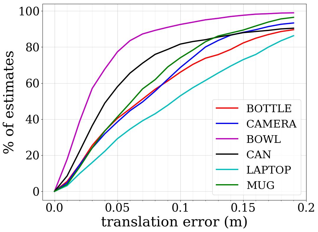
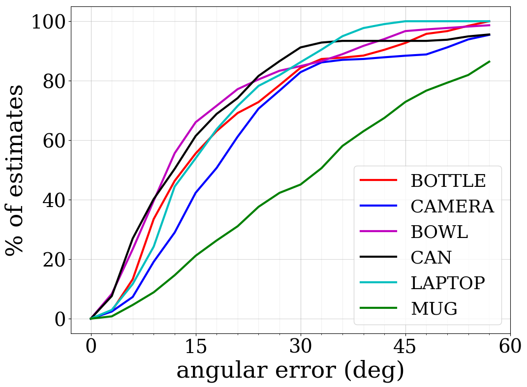
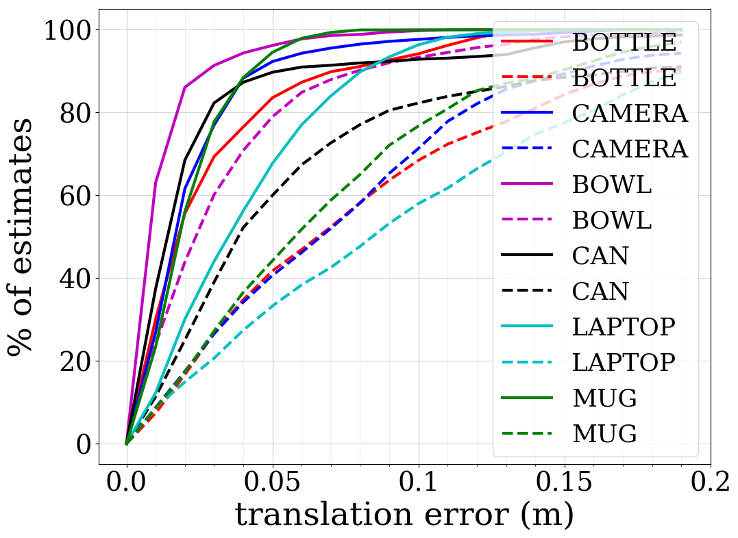
The average rotation and translation errors over each class are presented in Tab. 1 and the accuracy visualized in Fig. 3. Despite relying only on monocular images, MSL-RAPTOR achieves comparable performance to state-of-the-art methods that use RGB-D. As is expected for a monocular camera, depth estimates are less accurate than translations perpendicular to the agent’s camera axis (i.e. parallel to the image plane). This can be seen in Fig. 3 where these are broken out into separate errors. This is a problem that comes with the use of monocular images rather than RGB-D data.
4.3 Baseline evaluation in an aerial robotics scenario
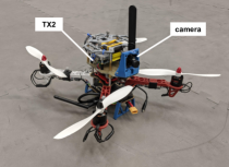
To demonstrate that MSL-RAPTOR provides robust onboard perception, we ran the algorithm onboard a drone with an Nvidia Jetson TX2 to track another drone. The ego quadrotor uses the DJI F330 frame and is equipped with off-the-shelf and custom made components as shown in Fig. 4. The quadrotor uses an RGB camera (640 480 resolution). Experiments were designed so that the ego drone moves about the experimental space causing the image background to change substantially, a challenge which demonstrates the robustness of the system. The flights varied from slow to aggressive, with the tracked object occasionally exiting and reentering the field of view or being occluded by other objects. As would be expected in collision avoidance situations, the distances between the ego and tracked drone routinely reached 8 meters (a substantially larger separation distance than what is seen in most existing pose estimation datasets). This provides important validation of the use of this method for planning and decision making onboard agile robots. From our collected data, we use 5500 images over several runs to form a training set for the detector and baseline, and use 5000 different images to form a testing set to evaluate pose predictions.
Implementation details
We do not assume knowledge about the control input of the tracked drones, and a simple constant velocity dynamics model is used. Since we are looking at tracking the other drone at up to 10 meters distance from the ego drone, we treat the tracked drone as symmetric about the vertical axis considering the yaw angle does not have an appreciable effect on our measurements, and does not provide useful information about its behavior. For a fair comparison, the same assumption is made for the baseline method. With a higher resolution camera or for tracking at closer ranges this constraint could be removed.
Baseline
While most state-of-the-art methods struggle to achieve real-time speeds on desktop GPUs, SSP [9] reports inference-only speeds of 50 Hz. This, in addition to its impressive accuracy, makes it the only candidate likely to be competitive when running onboard. SSP takes in an image and outputs the estimated locations of the projected 3D bounding box of the object on the image plane. Its network is based on YOLO’s architecture and is modified to produce the 3D bounding box projections instead of a 2D bounding box. The relative rigid body transformation is then calculated from the projected vertex locations and the 3D bounding box geometry using a PnP algorithm.
SSP requires the full object pose for each image when training. Outside of laboratory environments with specialized equipment, this is more challenging to acquire than the 2D bounding boxes used by MSL-RAPTOR. Moreover, SSP is presented as an instance-based method, meaning it must be trained on specific objects for which it will infer pose. For this reason, we did not evaluate it on the NOCS dataset that contains unseen objects instances in the testing set.
We train SSP using a desktop GPU, and present results for both SSP and MSL-RAPTOR evaluated on an Nvidia Jetson TX2.
Results
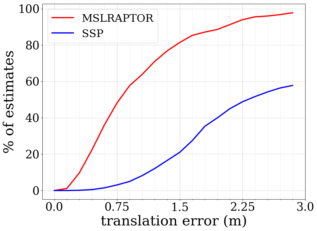
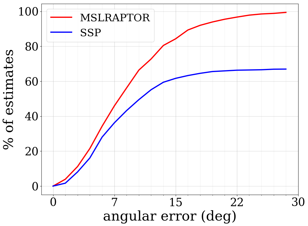
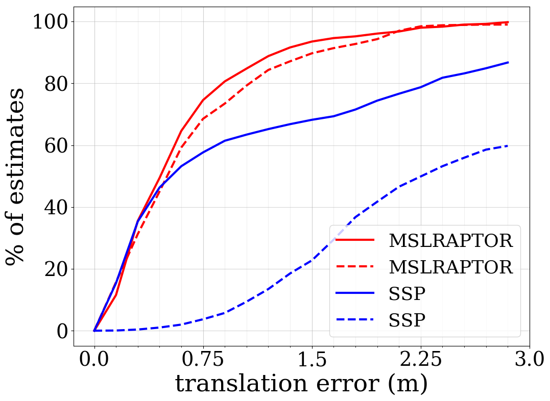
Fig. 5 shows the better accuracy of MSL-RAPTOR compared to SSP. The median translation and rotation errors are 0.82 m and 8.59 degrees for MSL-RAPTOR compared to 2.45 m and 11.26 degrees for SSP (66% less translation error and 23% less rotation error). When tracking a drone, MSL-RAPTOR runs 3X faster than SSP on a TX2, with an average pose prediction speed of 0.115 s (8.7 Hz) compared to 0.335 s (2.98 Hz) for SSP.
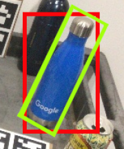
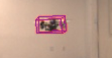
SSP directly outputs the locations of the 3D bounding box projections on the image, so when the drone is far away or moving quickly (causing blur), these points can be warped and scaled (Fig. 6). Regardless, the PnP algorithm will find a rigid body transformation that best matches these projections to the actual 3D bounding box, leading to significant depth errors as seen in Fig. 5. Since the in-plane translation is affected by the average of these points, and the rotation by the relative positioning, the difference in performance is less stark for the rotation and in-plane translation errors. As SSP does not incorporate temporal information it cannot identify nor correct for these situations which lead to estimates with large errors, resulting in the apparent asymptotes in Fig. 5.
5 Conclusions
In this paper, we propose MSL-RAPTOR, an efficient monocular relative pose tracking algorithm that combines the image processing capabilities of modern neural networks with the robustness advantages of classical probabilistic filters. The front-end extracts class labels and angled bounding boxes, which are used as observations by the back-end’s UKF. The back-end estimates the relative pose and returns measurement uncertainty parameters to the front-end for methodically determining when to trigger the slower, but more accurate, re-detection. When not detecting, the faster visual tracking method is used. The algorithm runs 3 times faster than the quickest state-of-the-art method, while still out-performing it in terms of precision in onboard robotic perception scenarios. Furthermore, despite not using depth measurements, comparable performance to state-of-the-art results is achieved on the NOCS-REAL275 dataset.
Acknowledgements
This research was supported in part by ONR grant number N00014-18-1-2830, NSF NRI grant 1830402, the Stanford Ford Alliance program, the Mitacs Globalink research award IT15240, and the NSERC Discovery Grant 2019-05165. We are grateful for this support.
References
- [1] Spica, R., Falanga, D., Cristofalo, E., Montijano, E., Scaramuzza, D., Schwager, M.: A Real-Time Game Theoretic Planner for Autonomous Two-Player Drone Racing. In: Proceedings of Robotics: Science and Systems, Pittsburgh, Pennsylvania (June 2018)
- [2] Badue, C., et al.: Self-driving cars: A survey. Expert Systems with Applications 165 (2021) 113816
- [3] Schmidt, T., Newcombe, R., Fox, D.: DART: Dense Articulated Real-Time Tracking. In: Proceedings of Robotics: Science and Systems, Berkeley, USA (July 2014)
- [4] Andriluka, M., Roth, S., Schiele, B.: Monocular 3D pose estimation and tracking by detection. In: Conference on Computer Vision and Pattern Recognition, IEEE (2010) 623–630
- [5] Xiang, Y., Schmidt, T., Narayanan, V., Fox, D.: PoseCNN: A Convolutional Neural Network for 6D Object Pose Estimation in Cluttered Scenes. In: Robotics: Science and Systems, Pittsburgh, Pennsylvania (2018)
- [6] Do, T.T., Pham, T., Cai, M., Reid, I.: Real-time Monocular Object Instance 6D Pose Estimation. In: British Machine Vision Conference (BMVC). Volume 1. (2018) 6
- [7] Rad, M., Lepetit, V.: BB8: A Scalable, Accurate, Robust to Partial Occlusion Method for Predicting the 3D Poses of Challenging Objects without Using Depth. In: Proceedings of the IEEE International Conference on Computer Vision. (2017) 3828–3836
- [8] Kehl, W., Manhardt, F., Tombari, F., Ilic, S., Navab, N.: SSD-6D: Making RGB-Based 3D Detection and 6D Pose Estimation Great Again. In: IEEE International Conference on Computer Vision. (2017) 1521–1529
- [9] Tekin, B., Sinha, S.N., Fua, P.: Real-Time Seamless Single Shot 6D Object Pose Prediction. In: IEEE Conference on Computer Vision and Pattern Recognition. (2018) 292–301
- [10] Lepetit, V., Moreno-Noguer, F., Fua, P.: EPnP: An Accurate O(n) Solution to the PnP Problem. International journal of computer vision 81(2) (2009) 155
- [11] Wang, H., Sridhar, S., Huang, J., Valentin, J., Song, S., Guibas, L.J.: Normalized Object Coordinate Space for Category-Level 6D Object Pose and Size Estimation. In: Proceedings of the IEEE Conference on Computer Vision and Pattern Recognition. (2019) 2642–2651
- [12] Wang, C., Martín-Martín, R., Xu, D., Lv, J., Lu, C., Fei-Fei, L., Savarese, S., Zhu, Y.: 6-PACK: Category-level 6D Pose Tracker with Anchor-Based Keypoints. In: IEEE Conference on Robotics and Automation (ICRA), Paris, France (May 2020)
- [13] Cho, H., Seo, Y.W., Kumar, B.V., Rajkumar, R.R.: A multi-sensor fusion system for moving object detection and tracking in urban driving environments. In: IEEE Conference on Robotics and Automation (ICRA). (2014) 1836–1843
- [14] Buyval, A., Gabdullin, A., Mustafin, R., Shimchik, I.: Realtime vehicle and pedestrian tracking for didi udacity self-driving car challenge. In: 2018 IEEE International Conference on Robotics and Automation (ICRA), IEEE (2018) 2064–2069
- [15] Redmon, J., Farhadi, A.: YOLOv3: An Incremental Improvement. arXiv:1804.02767 (2018)
- [16] Wang, Q., Zhang, L., Bertinetto, L., Hu, W., Torr, P.H.: Fast online object tracking and segmentation: A unifying approach. In: IEEE Conference on Computer Vision and Pattern Recognition. (2019) 1328–1338
- [17] Julier, S., Uhlmann, J., Durrant-Whyte, H.F.: A new method for the nonlinear transformation of means and covariances in filters and estimators. IEEE Transactions on Automatic Control 45(3) (March 2000) 477–482
- [18] Wan, E.A., Van Der Merwe, R.: The Unscented Kalman Filter for Nonlinear Estimation. In: Proceedings of the IEEE 2000 Adaptive Systems for Signal Processing, Communications, and Control Symposium. (2000) 153–158
- [19] Hartley, R., Zisserman, A.: Multiple View Geometry in Computer Vision. Cambridge University Press (2004)
- [20] Jocher, G., guigarfr, perry0418, Ttayu, Veitch-Michaelis, J., Bianconi, G., Baltacı, F., Suess, D., WannaSeaU, IlyaOvodov: ultralytics/yolov3: Rectangular Inference, Conv2d + Batchnorm2d Layer Fusion (April 2019)
- [21] Kristan, M., Matas, J., Leonardis, A., Vojir, T., Pflugfelder, R., Fernandez, G., Nebehay, G., Porikli, F., Čehovin, L.: A Novel Performance Evaluation Methodology for Single-Target Trackers. IEEE Transactions on Pattern Analysis and Machine Intelligence 38(11) (Nov 2016) 2137–2155
- [22] Issac, J., Wuthrich, M., Cifuentes, C.G., Bohg, J., Trimpe, S., Schaal, S.: Depth-based object tracking using a Robust Gaussian Filter. In: 2016 IEEE International Conference on Robotics and Automation (ICRA), Stockholm, Sweden (May 2016)
- [23] Wuthrich, M., Pastor, P., Kalakrishnan, M., Bohg, J., Schaal, S.: Probabilistic Object Tracking using a Range Camera. 2013 IEEE/RSJ International Conference on Intelligent Robots and Systems (Nov 2013)
- [24] Zhou, Q.Y., Park, J., Koltun, V.: Open3D: A Modern Library for 3D Data Processing. arXiv preprint arXiv:1801.09847 (2018)
- [25] Suwajanakorn, S., Snavely, N., Tompson, J.J., Norouzi, M.: Discovery of Latent 3D Keypoints via End-to-end Geometric Reasoning. In: Advances in Neural Information Processing Systems. (2018) 2059–2070