High-fidelity superconducting quantum processors via laser-annealing of transmon qubits
Abstract
Scaling the number of qubits while maintaining high-fidelity quantum gates remains a key challenge for quantum computing. Presently, superconducting quantum processors with 50-qubits are actively available. For such systems, fixed-frequency transmons are attractive due to their long coherence and noise immunity. However, scaling fixed-frequency architectures proves challenging due to precise relative frequency requirements. Here we employ laser annealing to selectively tune transmon qubits into desired frequency patterns. Statistics over hundreds of annealed qubits demonstrate an empirical tuning precision of 18.5 MHz, with no measurable impact on qubit coherence. We quantify gate error statistics on a tuned 65-qubit processor, with median two-qubit gate fidelity of 98.7%. Baseline tuning statistics yield a frequency-equivalent resistance precision of 4.7 MHz, sufficient for high-yield scaling beyond 103 qubit levels. Moving forward, we anticipate selective laser annealing to play a central role in scaling fixed-frequency architectures.
I Introduction
Recent technological advances have enabled rapid scaling of both the physical number of qubits and computational capabilities of quantum computers [1, 2, 3, 4]. The distinction between classical and quantum computing arises from the exponentially larger computational subspace available to qubits (quantum bits), which may be set to non-classical superpositions and entangled states. Existing multi-qubit systems built on superconducting circuit quantum electrodynamics (cQED) architectures [5, 6] have been utilized in applications ranging from early implementations of Shor’s factoring algorithm [7], to quantum chemistry simulations [8, 9, 10] and accelerated feature mapping in machine-learning [11, 12]. Presently, solid-state cQED-based processors have significantly increased in scale [13, 14], with dozens of physical qubits demonstrated on a single quantum chip. As gate fidelities improve and eventually reach thresholds required for fault-tolerance, quantum advantage will be exploited to simulate complex molecular dynamics and implement quantum algorithms on practical scales [15, 16, 17]. To track the continual progression of quantum processing power, the quantum volume (QV) metric is used as an overall measure of the computational space available for a given processor [4].
Amongst the major classes of superconducting qubits, fixed frequency transmons [5, 2] operating in the EJ EC regime are attractive for their low charge dispersion, yielding relatively noise-immune qubits with coherence times (T1, T2) exceeding 100 s [18]. Transmon qubits are amenable to high fidelity ( 99.9%) single-qubit gate operations [2], and two-qubit entangling cross-resonance (CR) gates [19] are realized via static qubit-qubit coupling activated by an all-microwave drive scheme [2, 20]. A key requirement to enable high-fidelity CR gates involves the selective addressability of fixed-frequency transmons, as well as precisely engineering their computational transitions (f01) for optimal two-qubit interaction [2]. For example, sub-optimal f01 separation between neighboring qubits reduces ZX coupling strength whilst higher-order static ZZ interactions cause accumulation of two-qubit errors as well as ‘spectator’ error propagation across the lattice [21]. The most likely frequency collisions and corresponding tolerance bounds resulting from frequency crowding of lattice transmons have been quantitatively enumerated in [22].
The principal challenge for scaling fixed-frequency architectures is mitigating errors arising from lattice frequency collisions. Typical fabrication tolerances for transmon frequencies range from 1-2%, with uncertainties dominated by the 2-4% variation in tunnel junction resistance Rn [22, 23]. Thermal annealing methods to adjust and stabilize post-fabrication Rn (and correspondingly, transmon frequencies f01) have been explored previously in [24, 25, 26, 27]. More recently, the LASIQ (Laser Annealing of Stochastically Impaired Qubits) technique was introduced to increase collision-free yield of transmon lattices by selectively trimming (i.e. tuning) individual qubit frequencies via laser thermal annealing [22]. The LASIQ process sets Rn with high-precision, and f01 could be predicted from Rn according to a power-law relationship resulting from the Ambegaokar-Baratoff relations and transmon theory [28, 5]. An empirical f01(Rn) scatter of 14 MHz limited the ability to predict f01 from Rn, resulting in a post-tune fequency precision of equivalently 14 MHz [22].
Here, we demonstrate LASIQ as a scalable process tool used to reduce two-qubit gate errors by systematically trimming lattice transmon frequencies to desired patterns. We show laser tuning results on statistical aggregates of 300 tuned qubits, and demonstrate LASIQ baseline frequency-equivalent resistance tuning precision of 4.7 MHz from empirical f01(Rn) correlations, reaching this precision with 89.5% success rate. Based on cryogenic f01 measurements from our laser-tuned processors, we empirically find a frequency assignment precision of 18.5 MHz, which in addition to the LASIQ tuning precision includes all deviations arising from pre-cooldown steps including post-tuned chip cleaning and bonding processes. Our results indicate the precision of trimming f01 is dominated by the residual f01(Rn) scatter of untuned qubits ( = 18.1 MHz), and is not limited by the LASIQ trimming process itself.
In addition to scaling the number of tuned qubits, we measure functional parameters of multi-qubit chips (coherence and two-qubit gate-fidelity) to ensure high processor performance. We assess the impact of LASIQ tuning on qubit coherence using a collection of composite (partially tuned) processors, showing aggregate mean T1 and T2 times of 79 16 s and 69 26 s respectively, with no statistically significant variation between the tuned and untuned groups. Our LASIQ process has been broadly utilized for precise frequency control of post-fabricated 27-qubit Falcon processors, including the recent QV-128 ibmq_montreal system [4, 29]. We demonstrate LASIQ scaling capabilities by tuning a 65-qubit Hummingbird processor (cloud-accessible as ibmq_manhattan), with a median two-qubit gate fidelity of 98.7% based on randomized benchmarking [30, 2]. As a scalable frequency trimming tool for fixed frequency transmon architectures, we envision the LASIQ process to be widely implemented in future generations of superconducting quantum systems.
II Results
II-A Tuning a 27-qubit Falcon processor
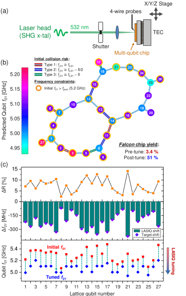
As a practical demonstration of frequency trimming, a 27-qubit Falcon processor is tuned to predicted frequency targets using the LASIQ setup shown in Fig. 1(a) (described in Methods). The Falcon chip series are based on a heavy-hexagonal lattice, which contains the distance-3 hybrid surface and Bacon-Shor code for error correction [31]. For this demonstration, all measurements were performed at ambient conditions, with resulting tuned frequencies estimated from empirical f01(Rn) correlations. The tuned lattice is depicted in Fig. 1(b), with a color heatmap indicating the post-LASIQ frequency predictions. Nearest-neighbor (NN) qubit frequency spacing (fNN) can visually be seen to be separated by 50 MHz 250 MHz, placing qubits comfortably within the straddling regime for high-ZX interaction [32]. NN collisions have been avoided with twice the collision tolerance (2, see Supplementary Information) from bounds described in [22], to protect against two-qubit state hybridization and improve chip yield. Prior to tuning, high-risk pairs within 2 collision bounds have edge borders highlighted as indicated in the lattice graph, and are resolved after the LASIQ process is complete. Based on Monte Carlo models with a conservative post-tune spread estimate of = MHz (Sec. II-B), we demonstrate substantial increase in the yield rate from 3.4% to 51% for achieving zero NN collisions, corresponding to 15 yield improvement after LASIQ tuning (see Supplementary Information). The target qubit f01 patterns corresponding to Fig. 1(b) are shown in the bottom panel of Fig. 1(c), where initial f01 (red) are progressively tuned until they reach pre-defined and distinct frequency setpoints (blue).
In addition to NN collision avoidance, all qubits have been tuned to targets at or below fpurc = 5.2 GHz, which in our Falcon design is the cutoff for maintaining good Purcell protection and avoiding radiative qubit relaxation [33]. Due to the monotonic increase of junction resistance (Rn) intrinsic to the laser anneal process, qubit frequencies are ‘trimmed’ (i.e. reduced) to desired f01 values. The LASIQ process is engineered to proceed until Rn for all junction reside within 0.3% of the target RT (corresponding to 10 MHz for typical f01(Rn) correlation coefficients), although a nominal LASIQ approach will typically outperform this upper precision bound (Sec. II-B). The center panel of Fig. 1(c) shows desired target shifts (purple diamonds) superimposed on final predicted frequency tuning amplitudes (green bars), indicating excellent agreement with desired target values. The root-mean square (RMS) Rn deviation from RT for this processor is %, corresponding to a frequency-equivalent resistance tuning precision of 4.8 MHz (using nominal f01(Rn) power-law coefficients for this sample), and is consistent with LASIQ baseline tuning precision as described in Fig. 2. As seen from the center panel, target f01 shifts range from 75 MHz (Qubit 8) to 375 MHz (Qubit 21) in Fig. 1(c), corresponding to resistance shifts up to Rn = 14.2%. Based on separate calibration measurements over standard junction arrays, resistance tuning peaks at 14%, and therefore tuning plans for each processor are designed to be constrained within attainable targets. Upon completion of the LASIQ process, a typical quantum processor is cooled and screened for coherence and single/two-qubit gate fidelity, and assessments of quantum volume are performed [4]. Two-qubit gate error statistics of a tuned and operational 65-qubit Hummingbird processor are shown in Sec. II-C.
II-B LASIQ tuning precision
In prior work, tuning precision estimates were limited by the imprecision in predicting f01 from room-temperature Rn measurements [22]. Thus, only an upper bound of tuning precision could be determined ( 14 MHz). Presently, we address the limits of LASIQ tuning precision as limited by the process itself, rather than our ability to predict cryogenic f01(Rn). We analyze a large sample of 390 tuned qubits, 349 of which successfully tuned to target (defined in Sec. II-A as achieving junction resistance within 0.3% of RT), yielding an aggregate tuning success rate of 89.5% for this experiment. The initial and final distributions of successfully tuned qubits are shown in Fig. 2. We note here that a full range of tuning (R up to 14% with respect to initial junction Rn) was performed for this experiment, with anticipated failure rates being weighted towards tuning extremes (R 14% increases undershoot risk, whilst low tuning R 1% results in increased overshoot risk). Such extremes are readily avoided during f01 tuning plan assignment. A detailed analysis of tuning statistics and success rates has been performed for all qubits (see Supplementary Information).
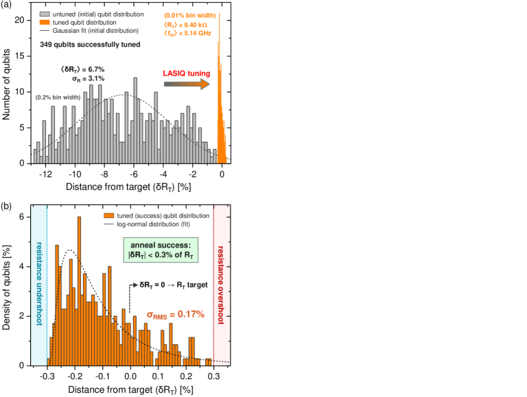
To understand the consequences of the incremental approach to RT, aggregate tuning statistics of the 349 successfully tuned qubits are depicted in Fig. 2(a). Rn of the initial qubits (gray histogram) are tuned to a tight tolerance about the targets (orange), as displayed on a RT normalized scale. A Gaussian fit approximates the initial resistance distribution, yielding a mean fractional tuning distance of 6.7% (with respect to RT). The final distribution is magnified in Fig. 2(b) with a superimposed log-normal curve fit, a characteristic distribution for fractional growth processes consistent with incremental anneals during the LASIQ process. Averaging over the entire distribution yields a RMS error deviation R = 0.17% from RT, corresponding to f = = 4.7 MHz as determined by empirical f01(Rn) correlations from our 65-qubit Hummingbird processor (Fig. 3). Our determination of LASIQ resistance precision shows that the fundamental tuning performance is well below the upper bound of 14 MHz determined in [22], where it was also noted that this bound was dominated by residual scatter in the prediction of cryogenic f01 from room temperature Rn. Based on Monte Carlo simulations, a precision of 6 MHz is required for high-yield scaling for quantum processors beyond 103 qubits [22]. Therefore, our baseline frequency-equivalent resistance precision of f 5 MHz demonstrates LASIQ as a viable post-fabrication trimming process for high-yield scaling of fixed frequency transmon processors.
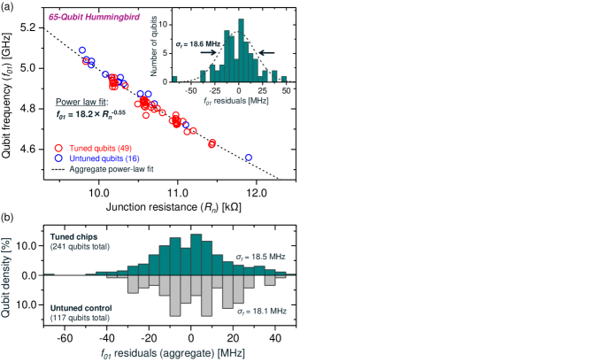
In addition to the residual f01(Rn) prediction scatter, a number of preparatory cleaning, bonding and processor mounting steps are undertaken for our quantum processors in the pre-cooldown stage. A natural question therefore arises as to the practical precision achieved for frequency assignment with the inclusion of such processes. Fig. 3(a) shows cryogenic f01 plotted against post-LASIQ measurements of Rn on a 65-qubit Hummingbird processor, which comprised 49 tuned qubits and 16 untuned qubits. Post-tuning, the processor underwent plasma cleaning and flip-chip bump-bonding to an interposer layer prior to mounting in a dilution refrigerator for cooldown and screening (see Methods). The entire process occurred within a 24-hour span to minimize the impact of aging and drift on the junction resistances (and therefore qubit frequencies). A power-law fit (dashed curve) conforms well to both the tuned and untuned qubits, indicating that no appreciable relative shifts due to LASIQ tuning have occurred, and that the same f01(Rn) prediction may be adequately utilized in both cases. We note the slight deviation of the power-law fit exponent (-0.55) from the nominal one-half expected from the Ambegaokar-Baratoff relations and transmon theory [28, 5], which is attributed to non-idealities in predicting f01 from room-temperature Rn. Nevertheless, this deviation to first-order does not affect the relative frequency spacing between qubits, and therefore does not impact the precision to which we assign qubit frequency spacing for collision avoidance. The effective f01 assignment precision may be determined by the residuals of the power-law fit as shown in the inset of Fig. 3(a), outlined by a Gaussian distribution with f = 18.6 MHz spread, corresponding to 0.38% of the mean qubit frequency (4.84 GHz), and defines the practical f01 assignment precision for this chip.
Fig. 3(b) shows a similar analysis performed over a statistical sampling of 241 qubits from 7 Falcon and 2 Hummingbird tuned processors. Each processor sample was fit to an individual f01(Rn) curve and residuals are aggregated in the upper histogram (dark green), with 1-f spread of 18.5 MHz, consistent with the single-processor sample observed in Fig. 3(a). Results from control (untuned) qubits are shown in the bottom panel histogram (gray), which are f01(Rn) residuals extracted from 117 untuned qubits on composite (partially tuned) processors, yielding 1-f spread of 18.1 MHz. We may therefore conclude that the f01 assignment imprecision resulting from our LASIQ process is a negligible contributor to the overall frequency spread of the qubits. We note that although our residual value for both tuned and untuned samples is larger than the 14 MHz demonstrated in [22], our Falcon and Hummingbird processors undergo significantly more preparatory steps prior to cooldown and a certain amount of deviation is anticipated. The prediction imprecision of f01(Rn) remains the dominant contributor to overall spread, with relatively smaller contributions from post-tune drifts and pre-cooldown processes. Significant room remains for improving frequency predictions to reach single-MHz levels dictated by the 5 MHz LASIQ baseline frequency-equivalent tuning precision as shown in Fig. 2(b) (details in Sec. III).
II-C Qubit coherence and gate fidelity
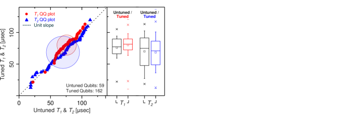
Maintaining high qubit coherence is an essential component of high-fidelity single- and two-qubit gates, in addition to precise frequency control. To empirically determine the impact of laser-tuning on qubit coherence, a composite (partially tuned) set of 4 Hummingbird processors were cooled and coherence was assessed. Out of a total 221 measured qubits from the 4 composite processors, 162 were LASIQ-tuned and 59 were left untuned (73% fractional tuning rate). The statistical aggregate is shown in Fig. 4 where tuned and untuned relaxation (T1, red) and dephasing (T2, blue) times are correlated on a quantile-quantile plot (left panel). Good correspondence is observed with respect to linear unity slope, indicating that distributions of coherences remain unaffected by tuning. Visual indicators of the mean T1 and T2 and 1- bounds are shown in the shaded ovals, with aggregate (including both tuned and untuned qubits) relaxation and dephasing times of 79 16 s and 69 26 s respectively. A direct comparison between tuned and untuned qubits indicates that for tuned (untuned) qubits, T1 = 80 16 s (76 15 s) and T2 = 68 25 s (70 26 s). Corresponding box-plots (interquartile box range, with 10-90% whiskers) are shown in the right panel, demonstrating that within statistical error, no variation in qubit coherence is observed due to the LASIQ process.
As a practical demonstration of LASIQ tuning capabilities, a 65-qubit Hummingbird processor is laser-tuned and operationally cloud-accessible as ibmq_manhattan. In a similar fashion to that shown in Fig. 1(a), the LASIQ tuning plan is generated by ensuring avoidance of nearest-neighbor (NN) level degeneracies whilst maintaining level separation within the straddling regime [32]. Post-LASIQ, the 65-qubit processor was cooled and qubit frequencies were measured, with density of frequency detuning between two-qubit gate pairs shown in the top panel of Fig. 5 (orange, 10 MHz bin width), along with the initial two-qubit detuning (blue, 30 MHz bins). As-tuned, our processor consists of 72 operational two-qubit CR gates, with gate durations ranging from 250 to 600 ns. Collision boundaries (2 bounds as derived from [22, 32], see Supplementary Information) for NN degeneracies are shown in the background, consistent with those utilized in Fig. 1(a) indicating that 20% of gates are within ‘high-risk’ collision zones. Indeed, Monte Carlo yield modeling of the untuned (as-fabricated) 65-qubit Hummingbird chip indicates an average of 12 NN collisions (assuming nominal 20 MHz spread with collision bounds), with an effectively null yield of zero NN collisions. These yield and collision outcomes are typical of untuned processor samples of this size. Post-LASIQ, the collisions are resolved, as evidenced by the high median two-qubit gate fidelity (98.7%) shown in the lower panel. The corresponding ZZ statistics are shown in the middle panel, indicating good separation near null-detuning (type-1 collision), whilst maintaining tight ZZ distribution with median 69 kHz (23.2 kHz). We note that transmon-transmon coupling suffers from static-ZZ (i.e. ‘always-on’) error; however, within the fj,k regime (anharmonicity –330 MHz, see Methods), tailoring the ZZ distribution to present magnitudes (70 kHz) with collision-free detuning is sufficient to yield gate errors approaching 10-2 for typical two-qubit CR gate durations of 400 ns, indicating that our two-qubit gate-fidelities are near levels set by coherence [21].
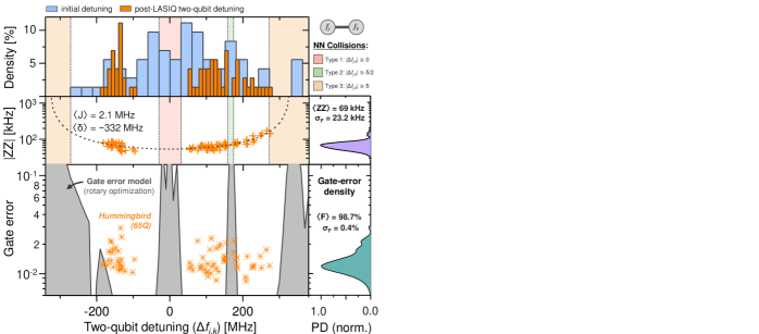
Two-qubit gate errors as a function of qubit-pair detuning are displayed in Fig. 5 (bottom panel), with their associated distribution shown in the adjacent probability density map (right). Notably, our detuning distribution shows more gates with positive control-target detuning, as expected given the greater ZX interaction in the positive detuning region. A CR gate error model is also depicted in the figure (see Methods), where the shaded background (gray) indicates low-fidelity regions consistent with known frequency collisions described in [22]. As part of our model, an optimizer routine incorporates a standard CR echo sequence with optional target rotary pulsing to determine usable two-qubit detuning regions within the straddling regime. For a gate-error of 1%, a total usable frequency range of 380 MHz is available (optimized using J = 1.75 MHz in the depicted model), which reduces to 350 MHz (130 MHz) for error targets of 0.5% (0.1%). Finally, we note that our depicted model does not incorporate the impacts of classical crosstalk and coherence, the latter of which limits gate error in the desirable detuning regions. We note that although our collisions bounds and unitary gate model have similar qualitative outcomes, further work is required to determine exact collision constraints and identify high-fidelity detuning regimes as lattice sizes are progressively increased.
III Discussion
Significant yield improvement and high two-qubit gate fidelities for both Falcon and Hummingbird processors demonstrate LASIQ as an effective post-fabrication frequency trimming technique for multi-qubit processors based on fixed-frequency transmon architectures. Selective laser annealing offers a compelling and scalable solution to the problem of frequency crowding, with LASIQ being readily adaptable to the scaling of qubits on progressively larger quantum processors. Based on Monte Carlo models [22] the 4.7 MHz frequency-equivalent resistance tuning precision of LASIQ allows high-yield scaling up to and beyond the 1000-qubit level. At present, cryogenic f01 measurements indicate a practical precision of 18.5 MHz; however, statistical analysis of cryogenic-to-ambient thermal cycling in a dilution refrigerator yields a re-cool stability of 5.7 MHz for our multi-qubit processors, which may be leveraged to obtain f01(Rn) predictions with similar accuracy and approach the baseline frequency assignment precision allowed by LASIQ. Finally, we note that despite our present emphasis on nearest-neighbor (NN) collisions, errors arising from next-NN qubits (e.g. spectator collisions) are a rising concern with lattice scaling, and future work will incorporate tuning plans to minimize such errors, as well as lattice frequency pattern optimization for yield maximization.
IV Methods
IV-A Laser annealing for transmon frequency allocation
The LASIQ frequency tuning system is depicted in Fig. 1(a), whereby a diode-pumped solid-state laser (532 nm) is actively aligned and focused on a multi-qubit quantum processor to selectively anneal individual transmon qubits [22]. A timed shutter precisely controls the anneal duration and monotonically increments the junction resistance over multiple exposures, with intermediate resistance measurements to aid the adaptive approach to target resistances (RT). Diffractive beam shaping is optionally available to aid in the uniform thermal loading of the junction [35]. The LASIQ process is fully automated and tunes an entire chip to completion, which occurs when each junction is annealed to within 0.3% tolerance around RT (corresponding to 10 MHz for typical f01(Rn) correlations).
IV-B Preparation and screening of multi-qubit processors
The Josephson junctions are fabricated via standard electron beam lithographic patterning followed by two-angle shadow evaporation with intermediate oxidation for Al/AlO2/Al junction formation [36]. Typical lateral dimensions of the junction are 100 nm, which yield as-fabricated frequency deviations near 2%, corresponding to 100 MHz of qubit frequency spread. Transmon qubit designs follow those described in [4, 22], with coupled qubits in a fixed-frequency lattice architecture. Nominal qubit anharmonicities are engineered near –330 MHz. Following junction evaporation, pre-screening of viable processor candidates are performed via room-temperature resistance measurements of all Josephson junctions, with transmon qubit frequencies estimated through wafer-level resistance-to-frequency power-law fits from prior control experiments. Candidates are ranked based on suitability for LASIQ tuning into collision-free tuning plans and within the Purcell filter bandwidth, all under the constraint of tuning range limits (typical maximum resistance tuning of 14%). Following this pre-selection process, a frequency plan is generated and tested through Monte Carlo collision and yield modeling [22]. Automated LASIQ tuning is performed as defined by the tuning plan for each transmon qubit to a junction resistance precision band of 0.3%, which yields an as-tuned RMS frequency-equivalent resistance precision 5 MHz (Sec. II-B). Post-LASIQ, the multi-qubit processors are plasma-cleaned and flip-chip bonded to an interposer layer for Purcell filtering and readout. The bonded processors are mounted into a dilution refrigerator for cryogenic screening, including coherence measurements and single- and two-qubit gate-error analysis. The post-LASIQ cleaning, bonding and mounting steps are coordinated to occur within a 24-hour span to minimize junction aging and drifts, thereby maintaining the qubits faithfully outside collision bounds of the intended tuning frequency plans.
IV-C Gate-error model
Our gate error estimates are the result of time-domain simulations of the Schrodinger equation within the full Duffing model of two coupled transmon qubits [32]. CR pulses are modeled as “Gaussian square” in shape. For each set of parameters, CR gate amplitudes are tuned up in a two-pulse echo for a fixed gate time by minimizing the Bloch vector [4]. A rotary pulse is additionally applied to the target qubit during the CR pulses, the amplitude of which is optimized to minimize gate error, as described in [21]. Using an adaptive Runge-Kutta solver, we calculate the full unitary evolution of the system resulting from the calibrated gate sequence. From this simulated unitary , error can be estimated by (where and for our two-qubit simulations) and is compared to the results of two-qubit randomized benchmarking.
References
- [1] D. P. DiVincenzo, “The physical implementation of quantum computation,” Fortschr. Phys., vol. 48, no. 9-11, pp. 771–783, 2000.
- [2] J. M. Gambetta, J. M. Chow, and M. Steffen, “Building logical qubits in a superconducting quantum computing system,” NPJ Quantum Inf., vol. 3, no. 1, p. 2, 2017.
- [3] M. H. Devoret and R. J. Schoelkopf, “Superconducting circuits for quantum information: an outlook,” Science, vol. 339, no. 6124, pp. 1169–1174, 2013.
- [4] P. Jurcevic, A. Javadi-Abhari, L. S. Bishop, I. Lauer, D. F. Bogorin, M. Brink, L. Capelluto, O. Günlük, T. Itoko, N. Kanazawa, A. Kandala, G. A. Keefe, K. Krsulich, W. Landers, E. P. Lewandowski, D. T. McClure, G. Nannicini, A. Narasgond, H. M. Nayfeh, E. Pritchett, M. B. Rothwell, S. Srinivasan, N. Sundaresan, C. Wang, K. X. Wei, C. J. Wood, J.-B. Yau, E. J. Zhang, O. E. Dial, J. M. Chow, and J. M. Gambetta, “Demonstration of quantum volume 64 on a superconducting quantum computing system,” arXiv:2008.08571, Aug. 2020.
- [5] J. Koch, T. M. Yu, J. Gambetta, A. A. Houck, D. I. Schuster, J. Majer, A. Blais, M. H. Devoret, S. M. Girvin, and R. J. Schoelkopf, “Charge-insensitive qubit design derived from the Cooper pair box,” Phys. Rev. A, vol. 76, no. 4, p. 042319, 2007.
- [6] A. Blais, R.-S. Huang, A. Wallraff, S. M. Girvin, and R. J. Schoelkopf, “Cavity quantum electrodynamics for superconducting electrical circuits: An architecture for quantum computation,” Phys. Rev. A, vol. 69, no. 6, p. 062320, 2004.
- [7] E. Lucero, R. Barends, Y. Chen, J. Kelly, M. Mariantoni, A. Megrant, P. O’Malley, D. Sank, A. Vainsencher, J. Wenner, T. White, Y. Yin, A. N. Cleland, and J. M. Martinis, “Computing prime factors with a Josephson phase qubit quantum processor,” Nature Phys., vol. 8, no. 10, pp. 719–723, 2012.
- [8] J. Argüello-Luengo, A. González-Tudela, T. Shi, P. Zoller, and J. I. Cirac, “Analogue quantum chemistry simulation,” Nature, vol. 574, no. 7777, pp. 215–218, 2019.
- [9] S. McArdle, S. Endo, A. Aspuru-Guzik, S. C. Benjamin, and X. Yuan, “Quantum computational chemistry,” Rev. Mod. Phys., vol. 92, no. 1, p. 015003, 2020.
- [10] N. Moll, P. Barkoutsos, L. S. Bishop, J. M. Chow, A. Cross, D. J. Egger, S. Filipp, A. Fuhrer, J. M. Gambetta, M. Ganzhorn et al., “Quantum optimization using variational algorithms on near-term quantum devices,” Quantum Sci. Technol., vol. 3, no. 3, p. 030503, 2018.
- [11] M. Schuld and N. Killoran, “Quantum machine learning in feature hilbert spaces,” Phys. Rev. Lett., vol. 122, no. 4, p. 040504, 2019.
- [12] V. Havlíček, A. D. Córcoles, K. Temme, A. W. Harrow, A. Kandala, J. M. Chow, and J. M. Gambetta, “Supervised learning with quantum-enhanced feature spaces,” Nature, vol. 567, no. 7747, pp. 209–212, 2019.
- [13] J. Preskill, “Quantum Computing in the NISQ era and beyond,” Quantum, vol. 2, p. 79, 2018.
- [14] D. Rosenberg, D. Kim, R. Das, D. Yost, S. Gustavsson, D. Hover, P. Krantz, A. Melville, L. Racz, G. Samach et al., “3d integrated superconducting qubits,” NPJ Quantum Inf., vol. 3, no. 1, pp. 1–5, 2017.
- [15] P. W. Shor, “Polynomial-Time Algorithms for Prime Factorization and Discrete Logarithms on a Quantum Computer,” SIAM Rev., vol. 41, no. 2, pp. 303–332, 1999.
- [16] L. K. Grover, “A fast quantum mechanical algorithm for database search,” Proceedings of the Twenty-Eighth Annual ACM Symposium on Theory of Computing, p. 212–219, 1996.
- [17] P. J. Karalekas, N. A. Tezak, E. C. Peterson, C. A. Ryan, M. P. da Silva, and R. S. Smith, “A quantum-classical cloud platform optimized for variational hybrid algorithms,” Quantum Sci. Technol., vol. 5, no. 2, p. 024003, 2020.
- [18] A. P. Place, L. V. Rodgers, P. Mundada, B. M. Smitham, M. Fitzpatrick, Z. Leng, A. Premkumar, J. Bryon, S. Sussman, G. Cheng, T. Madhavan, H. K. Babla, J. Berthold, A. Gyenis, N. Yao, R. J. Cava, N. P. de Leon, and A. A. Houck, “New material platform for superconducting transmon qubits with coherence times exceeding 0.3 milliseconds,” arXiv:2003.00024, Feb. 2020.
- [19] V. Tripathi, M. Khezri, and A. N. Korotkov, “Operation and intrinsic error budget of a two-qubit cross-resonance gate,” Phys. Rev. A, vol. 100, no. 1, p. 012301, 2019.
- [20] C. Rigetti and M. Devoret, “Fully microwave-tunable universal gates in superconducting qubits with linear couplings and fixed transition frequencies,” Phys. Rev. B, vol. 81, no. 13, p. 134507, 2010.
- [21] N. Sundaresan, I. Lauer, E. Pritchett, E. Magesan, P. Jurcevic, and J. M. Gambetta, “Reducing unitary and spectator errors in cross resonance with optimized rotary echoes,” arXiv:2007.02925, Jul. 2020.
- [22] J. B. Hertzberg, E. J. Zhang, S. Rosenblatt, E. Magesan, J. A. Smolin, J.-B. Yau, V. P. Adiga, M. Sandberg, M. Brink, J. M. Chow, and J. S. Orcutt, “Laser-annealing Josephson junctions for yielding scaled-up superconducting quantum processors,” arXiv:2009.00781, Sep. 2020.
- [23] J. M. Kreikebaum, K. P. O’Brien, A. Morvan, and I. Siddiqi, “Improving wafer-scale Josephson junction resistance variation in superconducting quantum coherent circuits,” Supercond. Sci. Tech., vol. 33, no. 6, p. 06LT02, 2020.
- [24] N. Muthusubramanian, A. Bruno, B. Tarasinski, A. Fognini, R. Hagen, L. Dicarlo, and Nandini Muthusubramanian Team, “Local trimming of transmon qubit frequency by laser annealing of Josephson junctions,” B. Am. Phys. Soc., vol. 64, no. 2, Mar. 2019.
- [25] T. Lehnert, D. Billon, C. Grassl, and K. H. Gundlach, “Thermal annealing properties of Nb-Al/AlOx-Nb tunnel junctions,” J. Appl. Phys., vol. 72, no. 7, pp. 3165–3168, 1992.
- [26] P. Koppinen, L. Väistö, and I. Maasilta, “Complete stabilization and improvement of the characteristics of tunnel junctions by thermal annealing,” Appl. Phys. Lett., vol. 90, no. 5, p. 053503, 2007.
- [27] J. S. Orcutt and S. Rosenblatt, “Adjustment of qubit frequency through annealing,” U.S. Patent 10,418,540, Sep. 2019.
- [28] V. Ambegaokar and A. Baratoff, “Tunneling between superconductors,” Phys. Rev. Lett., vol. 10, no. 11, pp. 486–489, 1963.
- [29] IBM Quantum, “Quantum Volume 128 on a 27-qubit Falcon processor,” in preparation, Dec. 2020.
- [30] E. Knill, D. Leibfried, R. Reichle, J. Britton, R. B. Blakestad, J. D. Jost, C. Langer, R. Ozeri, S. Seidelin, and D. J. Wineland, “Randomized benchmarking of quantum gates,” Phys. Rev. A, vol. 77, no. 1, p. 012307, 2008.
- [31] C. Chamberland, G. Zhu, T. J. Yoder, J. B. Hertzberg, and A. W. Cross, “Topological and Subsystem Codes on Low-Degree Graphs with Flag Qubits,” Phys. Rev. X, vol. 10, no. 1, p. 011022, 2020.
- [32] E. Magesan and J. M. Gambetta, “Effective hamiltonian models of the cross-resonance gate,” Phys. Rev. A, vol. 101, no. 5, p. 052308, 2020.
- [33] E. Jeffrey, D. Sank, J. Mutus, T. White, J. Kelly, R. Barends, Y. Chen, Z. Chen, B. Chiaro, A. Dunsworth, A. Megrant, P. O’Malley, C. Neill, P. Roushan, A. Vainsencher, J. Wenner, A. Cleland, and J. Martinis, “Fast accurate state measurement with superconducting qubits,” Phys. Rev. Lett., vol. 112, no. 19, p. 190504, 2014.
- [34] E. Pritchett, A. Kandala, and D. McKay, “Bounds on cross-resonance gate fidelity in an extended parameter regime,” B. Am. Phys. Soc., vol. 65, no. 1, Mar. 2020.
- [35] S. Rosenblatt and J. S. Orcutt, “Laser annealing of qubits with structured illumination,” U.S. Patent 10,170,681, Jan. 2019.
- [36] G. Dolan, “Offset masks for lift-off photoprocessing,” Appl. Phys. Lett., vol. 31, no. 5, pp. 337–339, 1977.
Acknowledgments
The authors acknowledge support for collision yield modeling and multi-qubit device characterization work under IARPA (Contract No. W911NF-16-0114). The authors also thank the IBM Microelectronics Research Laboratory and the Central Scientific Services for assistance with chip fabrication and handling, as well as associated control electronics. We thank M. Carroll, A. Rosenbluth and J. Gambetta for helpful discussions and feedback. We acknowledge the broader IBM team for their project support.
Data availability
The experimental and numerical simulation data found in this manuscript are available from the corresponding author upon reasonable request.
Author contributions
E.J.Z, Y.M. and J.S.O. constructed the LASIQ tuning system. E.J.Z., J.M.C. and J.S.O. conceived the experiments. S.S., N.S., D.F.B. and D.T.M. performed coherence and gate fidelity measurements of the multi-qubit chips. S.S., N.S., C.W., G.A.K., I.L., M.B.R., O.E.D. and M.B. helped design and fabricate the devices. J.B.H. built the Monte Carlo model for yield and collision simulations. E.J.Z. and J.B.Y. measured room temperature junction resistances. E.J.Z. performed the LASIQ tuning trials. J.S.O. and S.R. developed the LASIQ tuning method. J.T. and E.J.P. developed the numerical models for gate error estimation. W.L., E.P.L. and A.N. performed pre-cooldown preparations for the multi-qubit chips. E.J.Z., J.S.O., S.S., N.S., J.T., E.P. and J.M.C. prepared the manuscript with input from all authors.
V Supplementary Information
In this supplementary section we present and expand upon results of (A) Monte Carlo yield modeling of the tuned (and comparison against the untuned) 27-qubit Falcon processor presented in Sec II-A, and (B) Statistical analysis of tuning success rates as described in Sec. II-B.
V-A 27-qubit Falcon yield
In Sec II-A, an example 27-qubit Falcon processor was LASIQ-tuned for nearest-neighbor (NN) type 1-4 collision removal. To ascertain the impact of tuning on the NN collision-free yield rates, a Monte Carlo simulation [22] has been performed for the initial (pre-tuned) and final (post-tuned) transmon qubit frequencies, as predicted by typical power-law f01(Rn) curves for our sample. As described in [22], our model incorporates a random deviation (i.e. normal spread) from the target qubit frequencies, which may arise from empirical qubit spread from cleaning, bonding and cooldown processes (18.5 MHz), tuning imprecision (4.7 MHz), or other factors resulting in deviations from the desired target (Sec. II-B). We model the yield by adding to each target qubit frequency a random variation consistent with this frequency spread, and count the proportion of NN collision-free outcomes.
Fig. S1 shows the result of our yield models, indicating both the untuned (red) and tuned yield rates (blue) as a function of target frequency deviation. As-fabricated, the chip yields a significant number of type 1-4 NN collisions, as evidenced by the poorly conditioned untuned yield curve (red). The low yields for small f results from the presence of existing collisions immediately after fabrication and prior to tuning. However, even accounting for large random spreads, the initial untuned lattice frequency pattern is highly collision prone, with yields remaining under 5% for f 40 MHz. The poorly conditioned untuned yield curve is a general characteristic of fixed-frequency architectures that exhibit frequency crowding. The primary goal of our LASIQ tuning method to arrange our lattice frequency into well conditioned yield curves with high probability of achieving a NN collision-free configuration.
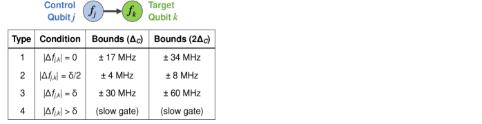
Fig. S2 tabulates the various NN collision types, as well as tolerance bounds around which collision avoidance is successfully achieved. As described in the main text and elaborated in [22], four main collision types are enumerated. Type-1 corresponds to two-qubit hybridization, with degenerate control (j) and target (k) level spacings. Type-2 results from two-photon excitation of j into the non-computational state, and type-3 poses similar risk when and vice-versa. Type-4 corresponds to a ‘slow gate,’ whereby reduced ZX interaction strength occurs due to two-qubit detuning beyond the straddling regime, resulting in longer gate operating times. The collision bounds are displayed in the third column of Fig. S2, numerically determined to yield 1% two-qubit gate errors [22, 32], and are consequently utilized in the Monte Carlo collision and yield models depicted in Fig. S1. In the process of generating tuning plans for LASIQ, we generally adopt the ‘best practice’ protocol of doubling these to 2 bounds shown in the final column of Fig. S2, which provide tuning plans with greater robustness to post-tuned drifts, and therefore yields NN collision-free tuned candidates with increased confidence.
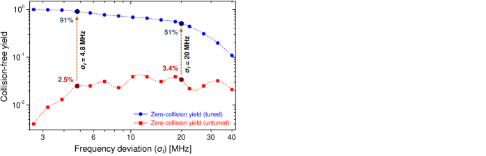
The tuning plan for this particular Falcon processor is outlined in Fig. 1(a), with the aim of tuning out NN collisions and ensuring frequencies reside within the Purcell filter bandwidth, while maintaining resistance tuning 14%. All qubits are successfully tuned to frequency targets with a predicted 4.8 MHz precision, as outlined in Sec II-A. The resulting Monte Carlo yield model of the tuned lattice pattern is shown by the well-conditioned (blue) curve in Fig. S1, indicating a typical yield roll-off as the frequency deviation increases. For nominal practical spreads (20 MHz, Sec. II-B), we calculate a yield improvement of 15, from 3.4% to 51%, indicating the efficacy of the LASIQ tuning method. A similar comparison is performed for the baseline precision achievable by LASIQ, which is predicted at 4.8 MHz for this chip (based on 0.16% post-LASIQ resistance precision), and indicates NN collision-free yields beyond 90%. As lattice sizes are scaled to 103 qubit levels, practical tuning precisions approaching these single-MHz levels will be required to ensure appreciable yields. Presently, a major contributor to our practical trimming precision results from the imprecision of predicting f01 from Rn [22], and significant gains may be achieved by leveraging processor recool cycles to tailor f01(Rn) predictions. In particular, statistics on qubit frequency deviations during cryogenic cycling yields a recool stability of 5.7 MHz (see Sec. III), which provides a practical pathway to approach the baseline precision of 5 MHz set by the frequency-equivalent resistance precision of our LASIQ process.
V-B Tuning success statistics
In Sec. II-B, a tuning sample of 349 Falcon qubits out of 390 total qubits were tuned to resistance targets (RT), spanning a tuning range up to 14.5% with 89.5% success rate. In this section we break down the tuning success statistics of the tuned qubits, and outline failure mechanisms which induce deviations from target resistances extending beyond the desired target band.
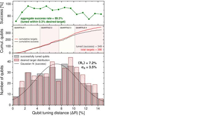
Fig. S3 shows the tuning statistics of all 390 qubits used in our precision benchmarking experiments. The bottom panel indicates the desired tuning histogram distribution (red, striped) with respect to initial junction resistance, superimposed upon the successfully tuned qubits (gray). Tuning success is defined as tuning to within 0.3% band around RT, and the LASIQ system will proceed incrementally towards this goal. A Gaussian distribution of the successfully tuned qubits is also depicted, with a mean tuned distance of 7.2% ( = 3.5%). We note here that each of the Falcon qubits was tuned as part of a tuning plan designed for NN collision avoidance, and hence our tuning distances are representative of realistic processor samples. It is notable that deviations between the desired (red, striped) and actual (gray) tuning distributions increasingly depart at both lower and higher tuning ranges, indicating that missed targets occur at the tuning distribution extremities.
The central panel of Fig. S3 indicates the cumulative plot of LASIQ tuned qubits, with both tuned total (red) and successfully tuned (black) qubits shown. Corresponding success rates for each tuning distance (assessed at 1% intervals) are displayed in the top panel, which indicates that failure rates are most likely ( 90% success) for tuning targets under 1% and above 10%. Below, we consider each case in turn.
In the former case, small desired tuning distances are exposed to risk of overshooting (i.e. R ). This is a result of the statistical spread in resistance progression, and small desired resistance shifts suffer increased risk of accidental increase beyond desired targets. Despite this risk, we note that typical optimal frequency separation between qubits in our tuning plans are on the order 100 MHz, and even for significant overshoot, NN collisions are unlikely to be induced unless the deviation between tuned resistances and targets approach the frequency spacing between NN qubits.
In the latter case, undershoot effects appear for junction targets beyond R 10%, as evidenced by the slow tapering down of success rates in the top panel of Fig. S3. This is a consequence of junctions reaching their maximum tuning limit, which based on calibration measurements on junction arrays, is near 14%, with a spread of 2%. In almost all cases, tuning plans are engineered to reside under 14% tuning, to ensure that almost all qubits on a given processor have high probability of reaching desired targets. Nevertheless, that statistical nature of the tuning range causes outlier qubits which saturate at lower R, resulting in monotonically decreasing success rates as observed in Fig. S3. Progress in scaling lattices of transmon qubits will benefit greatly from determining the origin of this resistance limit, and the best-practice fabrication processes through which this may be increased.