∎
11institutetext: Ulm University
Institute of Databases and Information Systems
Building O27 Level 5, James-Franck-Ring
89081 Ulm, Germany
11email: firstname.lastname@uni-ulm.de
Enacting Coordination Processes††thanks: This work is part of the ZAFH Intralogistik, funded by the European Regional Development Fund and the Ministry of Science, Research and the Arts of Baden-Württemberg, Germany (F.No. 32-7545.24-17/3/1)
Abstract
With the rise of data-centric process management paradigms, interdependent processes, such as artifacts or object lifecycles, form a business process through their interactions. Coordination processes may be used to coordinate these interactions, guiding the overall business process towards a meaningful goal. A coordination process model specifies coordination constraints between the interdependent processes in terms of semantic relationships. At run-time, these coordination constraints must be enforced by a coordination process instance. As the coordination of multiple interdependent processes is a complex endeavor, several challenges need to be fulfilled to achieve optimal process coordination. For example, processes must be allowed to run asynchronously and concurrently, taking their complex relations into account. This paper contributes the operational semantics of coordination processes, which enforces the coordination constraints at run-time. Coordination processes form complex structures to adequately represent processes and their relations, specifically supporting many-to-many relationships. Based on these complex structures, markings and process rules allow for the flexible enactment of the interdependent processes while fulfilling all challenges. Coordination processes represent a sophisticated solution to the complex problem of coordinating interdependent, concurrently running processes.
Keywords:
process interactions coordination process enactment operational semantics process choreography1 Introduction
Business process management, for the most part, is concerned with large, monolithic models of business processes (van der Aalst et al, 2000). Interactions between different business processes predominantly take place only if each business process belongs to a different organization (Object Management Group, 2011; van der Aalst, 2000). In practice, these cross-organizational business processes have been mostly limited to bidirectional one-to-one message exchanges, and interactions between business processes in a one-to-many relationship have been an afterthought at best. Consequently, concepts to model and describe the interactions between processes can support one-to-many interactions conceptually, but practically, they have been limited mostly to message exchanges between two processes. With the advent of data-centric process management, the postulate of only two interacting processes is no longer viable. In general, data-centric process management elevates data to a first-class citizen of a business process model and organizes data into objects with attributes. Each business process may comprise multiple different objects, and each of these objects possesses a lifecycle process that governs the way the object is processed over time, i.e., a lifecycle process describes object behavior. Therefore, the concepts of lifecycle process and object are mutually intertwined. The key idea of this object-centric variant of data-centric process management is that a business process is not prescribed by a monolithic model, but instead emerges from the interactions of objects and their lifecycle processes. In other words, a business process is constituted of interacting lifecycle processes in data-centric approaches using objects or artifacts (Nigam and Caswell, 2003; Künzle and Reichert, 2011). Generally, more than two types of processes have interactions, and the various process types may be in one-to-one, one-to-many as well as many-to-many relationships.
The emergence of the overall business process from interacting lifecycle processes possesses a fundamental property: It allows for a high degree of flexibility regarding the overall enactment of the business process (Künzle and Reichert, 2011; Hull et al, 2011a). The different objects and their lifecycle processes may be created and executed in very diverse ways, i.e., without too may constraints placed upon them. This is possible because data-centric approaches do not presume prescribed, imperative process choreographies that govern all object interactions in detail (e.g., (Decker and Weske, 2011)). Despite the absence of imperative process choreographies, one cannot necessarily assume that interacting lifecycle processes converge towards a meaningful overall business process on their own. As a consequence, the interactions between the lifecycle processes still require the enforcement of certain constraints at different points in time, which is denoted as process coordination in the following. Process coordination ensures that the processes and their interactions are guided towards a purposeful business process.
1.1 Problem Statement
For the convergence towards an overall business process, the interacting lifecycle processes require a coordination approach that preserves the inherent enactment flexibility of lifecycle processes. Regarding process coordination, several challenges were encountered during the design and conception of the object-aware approach to business process management (Künzle and Reichert, 2011). These challenges possess a high practical relevance, as they impact a successful enactment of an object-aware business process. These challenges represent issues that occur predominantly when one-to-many and many-to-many relationships between processes and the concurrent enactment of processes are concerned. Concurrent enactment and many-to-many-relationships are essential to the object-aware approach. The findings were supported by a systematic literature review on data-centric approaches to BPM (Steinau et al, 2018c), and by expert assessments (Marrella et al, 2015). When only one-to-one interactions of lifecycle processes are considered, these challenges exist as well, but are far less complicated to solve. Regarding the interacting lifecycle processes in one-to-many and many-to-many relationships, five main challenges may be identified: asynchronous concurrency, complex process relationships, local contexts, immediate consistency, and manageable complexity. These challenges are designated as main challenges for their relevance and complexity.
Each of these challenges states an optimum of what an approach for coordinating the interactions between lifecycle processes might support. Addressing all challenges together requires high sophistication and the development of new ways to deal with the coordination of processes. These challenges not only encompass the design-time, where lifecycle process and coordination models are specified, but in particular the run-time, where multiple instances of these models are concurrently executed. Much of the complexity of coordinating the lifecycle process interactions resides with the run-time.
1.2 Contribution
As one data-centric approach, object-aware process management (Künzle and Reichert, 2011) has encountered these challenges. Subsequently, a sophisticated solution to these challenges has taken shape over recent years: coordination processes (Steinau et al, 2018a). A coordination process is a high-level concept to specify and enforce the dependencies that exist between multiple interacting lifecycle processes. These dependencies between processes are called coordination constraints. In other words, a coordination process provides coordination for processes, i.e., such as lifecycle processes. The object and lifecycle process concept is not mandatory for coordination processes; in the following, a general notion of process is used that includes, but is not limited to, lifecycle processes. This notion is simply named a process, and is distinct from the notions of coordination process or business process.
Coordination processes alone are not able to resolve every challenge themselves. Instead, the concept of coordination processes is the keystone binding together two other fundamental concepts that revolve around the aforementioned challenges: the relational process structure and semantic relationships . A relational process structure captures process types and their relations, which may be one-to-many or many-to-many relations, at both design- and run-time. Interactions between processes only occur between related processes, i.e., a relation is a prerequisite for interactions between processes. Every process instance and its relations are tracked at run-time, enabling a complete overview over processes and their relations. Semantic relationships describe patterns inherent in the interactions between processes in a one-to-many relationship. Based on semantic relationships, sophisticated coordination constraints between multiple interacting processes can be expressed. Specifically, this paper builds upon
-
•
semantics relationships at design-time and state-based views (Steinau et al, 2017)
-
•
the design-time and run-time of relational process structures (Steinau et al, 2018b)
-
•
the design-time aspects of coordination processes (Steinau et al, 2018b)
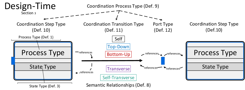
This paper subsequently presents all run-time aspects of coordination processes and semantic relationships, concluding the work started with (Steinau et al, 2017). A schematic view of coordination processes, the relational process structure, and semantic relationships is shown in Figure 1, indicating that all three concepts are inextricably linked.
One aspect of these efforts is that coordination processes are designed to be executable directly after instantiation from a respective coordination process type. In consequence, object-aware process management has achieved full design-time and run-time support for a data-centric approach, which has been accomplished only by very few other data-centric approaches to BPM (Steinau et al, 2018c). The implementation of the object-aware approach is named PHILharmonicFlows (Künzle and Reichert, 2011). PHILharmonicFlows has recently seen drastic changes due to moving to a microservice-based architecture (Andrews et al, 2018). Paramount for full run-time support is the operational semantics that describes how coordination processes are enacted. The operational semantics completely account for the new microservice-based architecture and the required adaptations in the concepts that constitute the basis for PHILharmonicFlows.
More specifically, the first contribution in enabling the enactment of a coordination process is the representation of process instances. A coordination process requires an internal representation of processes and their complex relations, i.e, one-to-many and many-to-many relationships, which is derived from the relational process structure (Steinau et al, 2018b). Coordination processes combine the derived representation of processes with components that describe the coordination constraints that restrict the interactions between processes. This combined representation enables the coordination process to actually enforce these coordination constraints at run-time, i.e., the enactment of the coordination process. The challenge here is that this combined representation is not fixed at run-time, but dynamically adapts to new relations and newly instantiated processes.
The second contribution are process rules. The operational semantics that describes how a coordination process is enacted is defined using a variant of event-condition-action (ECA) rules, denoted as process rules. Process rules read and write markings of elements in a coordination process instance, which indicate status information of process instances and the coordination process instance itself. The use of process rules and markings enables a highly flexible enactment of coordination processes, allowing to accommodate copious amounts of possible interactions, while prohibiting forbidden behavior in the interactions between process instances. This paper provides the set of process rules necessary to enact a coordination process. Furthermore, it describes the principles of how the process rules govern the enactment of a coordination process.
While the concept of coordination processes was devised in context of the object-aware approach, it is by no means limited to be employed only with object-aware processes. The design of coordination processes includes the possibility to coordinate any kind of processes, independently from the paradigm in which they are specified. Therefore, it is possible to coordinate interdependent activity-centric processes with a coordination process as well (Steinau et al, 2017, 2018b).
The remainder of the paper is organized as follows: Section 2 describes the problem of process coordination and presents a detailed description of the challenges that coordination processes aim to solve. Section 3 recaps the prerequisite concepts of the relational process structure and semantic relationships. Furthermore, the necessary background on coordination processes at design-time is presented. Section 4 gives a general overview over the enactment of coordination processes. The details of enacting a coordination process are presented in two distinct parts: Part one is shown in Section 5 and describes how process instances from the relational process structure and their semantic relationships are represented in a coordination process. Sections 4 and 5 contain the first contribution. Part two is presented in Section 6 and describes how process rules and markings are employed to enforce coordination constraints, constituting the second contribution. Sections 4-6 discuss the run-time of coordination processes and cover the contribution of this paper. The technical implementation of the operational semantics and the concept of coordination processes are presented in Section 7. Section 8 covers related work and discusses other approaches to process coordination. Section 9 concludes the paper with a summary and an outlook.
2 Challenges
The principal purpose of process coordination is to manage the complex interactions between two or more processes. In previous works, the interactions between processes in a one-to-one relationship, and typically in an inter-organizational setting, have been investigated (van der Aalst, 2000). As such, concepts for process coordination have been tailored to this setting. Extensions of this setting, e.g., the inclusion of one-to-many or many-to-many relationships or the interactions between more than two different types of processes, have been mostly neglected (zur Muehlen and Recker, 2013).
With data-centric process management, e.g., objects with lifecycle processes, the necessity has arisen to consider one-to-many and many-to-many relationships between multiple lifecycle processes of different types. With the advent of cloud computing and the Internet of Things (IoT), it may be further conjectured that small, interdependent processes will become increasingly important, for reasons of scalability in cloud environments and the complexity limitations of IoT devices.
Several new challenges have arisen due to the numerous requirements of data-centric approaches (Künzle and Reichert, 2011), and these additional challenges demand more sophisticated solutions. The principal promise of data-centric process management is the ability to support both unstructured and semi-structured business processes adequately. Previously, this kind of business processes could not be correctly represented with traditional process management approaches, e.g., BPMN 2.0. This is due to the extraordinary requirements regarding the flexibility of these business processes (Künzle and Reichert, 2009). One contribution for supporting this flexibility is the elimination of large, monolithic process models that encompass everything in favor of interdependent processes constituting the overall business process. These interdependent processes then need to interact and, therefore, require coordination. In consequence, much of the effort for realizing this flexibility is placed on the coordination approach that governs these process interactions. In particular, this effort is compounded by the requirements to support complex process relationships and multiple types of processes. As such, the flexibility promises of data-centric paradigms can be fulfilled if a coordination concept delivers a solution that meets the flexibility requirements. For a more systematic approach, five primary challenges have been identified that a coordination approach should fulfill in order to enable flexible interactions between different kinds of processes with complex relationships.
For illustrating these challenges as well as the concept of coordination processes and its operational semantics, a running example is used throughout the paper (cf. Example 1). It describes a recruitment business process in the human resource domain. Much of the complex behavior and interactions between different lifecycle processes may be observed in this rather simple setting.
Example 1 (Recruitment Business Process)
A company has an open position for which it wants to hire a suitable candidate. For this purpose, a company employee creates a and publishes it (e.g., on the company website). For this , interested persons may create . may be created as long as the is not closed, i.e, may arrive at different points in time at the company. For each that is sent to the company, an evaluation is started. Company experts must create for the application and give a recommendation on whether to invite the applicant for an or reject him outright. The overall recommendation requires at least three and a majority of 50% or more in favor of the applicant for an invite recommendation. Depending on the availability of the company experts and the arrival date of the respective application, may be created and completed at different points in time. If the overall recommendation favors the rejection of an applicant, the corresponding will be rejected. If the are in favor of the applicant, the applicant must be invited to at least one to further substantiate the suitability of the applicant for the open . If the majority of recommend hiring the applicant, the may be accepted, otherwise the will be rejected. Ties are resolved in favor of acceptance. At least one must be performed. However, only one may be accepted for each . Should an applicant have been hired, the is closed and given the final status “position filled” indicating success. Other applicants must consequently be rejected. The may be closed at any time as long as at least one has been sent to the company. If, after a reasonable amount of time, no suitable applicant can be found, the is closed, and its final status is set to “position vacant”.
In the following, five challenges in the context of advanced process coordination are characterized in detail. Coordination processes aim to fulfill all challenges.
2.1 Challenge 1: Asynchronous concurrency
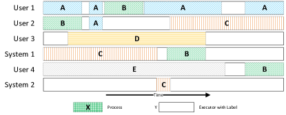
The first challenge relates to the concurrent and asynchronous enactment of processes. Processes may run concurrently to each other. Their concurrent enactment, however, is not required to be synchronized constantly, i.e., not every instance of a process is at the same stage at the same point in time. Instead, the enactment of a process is in principle fully asynchronous. At the one extreme, the enactment of multiple processes is sequential without any parallelism, i.e., a process is strictly enacted one after the other. At the other extreme, the enactment of the processes is fully parallelized, meaning every process enacts the same step at the same time. In between these extremes, processes may be enacted partially in parallel and partially sequential, where any combination is feasible. For example, one group of processes may be enacted in parallel, but sequentially after another group. Furthermore, the enactment of a process may be suspended and resumed at a later time, possibly by different actors. Actors may be users or systems in this context. Figure 2 shows a schematic view of asynchronously and concurrently enacted processes by different users or systems.
In practical scenarios, there may be dependencies between processes that restrict their concurrent enactment in some way. Of particular importance is that such coordination constraints do not restrict process enactment unnecessarily. Consider a process and another process , where must wait for a specific state of . When has reached that state, then can continue and subsequently must deliver a result back to , which may then proceed. In a naive implementation, process must wait for after has started until delivers the result. However, in principle, the result from might not be needed until a later point in the enactment of process . Therefore, it should be possible that continues running, while process is enacted in parallel, i.e., and run asynchronously and concurrently. This offers much more flexibility and performance, as unneeded waiting times do not occur. Only when the result from is absolutely needed for process to continue, should be forced to wait for .
In summary, as processes need to interact in order to form the overall business process, asynchronous concurrency of the processes opens up a myriad of possibilities for different processes to interact. A coordination approach should support these interactions as best as possible. As concurrent and asynchronous enactment is beneficial to the overall performance and flexibility of any interaction-focused paradigm, such as object-aware process management, an approach that coordinates processes should not unnecessarily restrict concurrent enactment. Consequently, the support of asynchronous concurrency in process enactment is the first challenge of process coordination. Note that this challenge is not solely associated with the conceptual level, but is also crucial for the implementation of a process management system. A practical occurrence of the first challenge can be illustrated with the running example (cf. Example 2).
Example 2 (Asynchronous Concurrency)
In Example 1, may be enacted in parallel to each other as well as to other types of processes, e.g., or . Depending on when an arrives, it may still be enacted in parallel, but with a time offset (cf. processes C and D of Figure 2). However, may only be started after the has been sent to the company. rely on a positive preliminary result from the associated with the . Note that the results of the may arrive at different points in time, i.e., asynchronously. Additionally, another may be processed in parallel to conducting an for the first . As can be seen, processes may run concurrently, but not without constraints placed upon them by the process coordination.
Challenge 1 Asynchronous Concurrency has been chosen for its importance for business processes in general and its impact on the performance of business process execution.
2.2 Challenge 2: Complex Process Relations
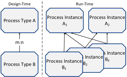
When representing an overall business process using interacting processes, it is likely that not just one instance of each process type is needed at run-time. Thus, multiple instances of each process type in the business process model may be created. These process instances do not exist independently from each other, but have interrelations (cf. Figure 3). For example, process instances may depend on multiple other process instances, which constitutes a one-to-many relationship. Moreover, process instances may be part of a many-to-many relationship with other process instances, introducing a significant increase in complexity compared to one-to-many relationships. Furthermore, processes may not only be directly related to other processes, but relations may form paths across different process types. This is called a transitive relationship, which, together with one-to-many and many-to-many relationships, leads to the creation of vast process structures of interrelated and, thus, interdependent processes. This structure of interrelated processes sets data-centric process management apart from the predominant one-on-one interactions of activity-centric processes—complex relationships between processes are part of the premise.
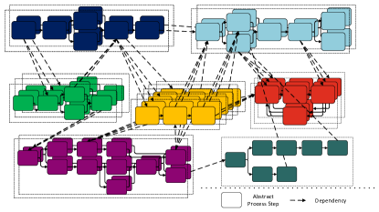
Managing and identifying these complex relationships at design-time and, more importantly, handling the emerging structure of process instances and their relations at run-time, constitutes the second challenge regarding process interactions that needs to be resolved. The challenge is compounded by the fact that processes and their relations are created and deleted over time. This results in a dynamic environment of a continually evolving process structure. In summary, process structures and their dynamic evolution must be taken into account when coordinating process interactions.
Example 3 (Complex Process Relations)
In Example 1, may be related to many , constituting a one-to-many relationship. At run-time, a must know which belong to it. In turn, each may be related to several and eventually some , which must be tracked and related accordingly as well. At any point in time, as long as the is not closed, may be newly created for the ,
or may be withdrawn or deleted, showing the dynamics of the process structure. are transitively related to and , e.g., it is possible to determine how many and have been performed in the context of a particular , as well as their status, at any point during run-time.
Challenge 2 Complex Process Relations has been chosen as business processes composed of smaller processes would be severely limited in their expressiveness with only simple one-to-one relations. Considering one-to-many and many-to-many relations for interacting processes has been well established in literature (Künzle and Reichert, 2009; Fahland et al, 2011; Meyer et al, 2013)
2.3 Challenge 3: Local Contexts
As multiple different objects exist that have different kinds of relationships, e.g., one-to-many, many-to-many, as well as transitive relationships, several implications can be observed at run-time. As shown before, process instances of different types form process structures because of their relations. In consequence, one process instance may be handled differently from another process instance of the same type simply because of the relations it has formed to other process instances. Thereby, some interconnected process instances form substructures within the overall process structure, denoted as arrangements. Arrangements are defined by the involved process instances as well as their exact relations (Steinau et al, 2017). An instance related to four instances is an example of an arrangement. An arrangement may therefore be subject to a local context. A local context represents individual constraints for the coordination of process interactions that must be handled individually, as part of an overall coordination effort. As opposed to this individualized approach, process choreography approaches in activity-centric process management always operate in the same context, as only one-to-one relations and no transitive relations have been considered. With many-to-many relations and transitive relations, the individual handling of emerging local contexts creates an entirely new challenge.
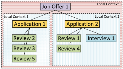
Numerous different local contexts may exist within the same process structure at the same time. More specifically, process instances and their arrangements may belong to different local contexts at the same time, i.e., local contexts may overlap or contain each other (cf. Figure 4). The arrangement consisting of as well as , , and is subject to its own local context (Local Context 1) and is included in the local context of (Local Context 3). Local contexts change over time due to changes in process relations. Altogether, the correct consideration of local contexts in the overall process coordination is crucial and therefore designated as the third challenge.
Example 4 (Local Contexts)
Each creates a local context together with its and . While each is embedded in the overall coordination of the local context of a (cf. Figure 4), each must also be handled individually. For one , may still be in progress and have not reached consensus yet (cf. Local Context 1, Figure 4), whereas for another ,
are being conducted (cf. Local Context 2, Figure 4). While must obey the same coordination constraints in general, due to their local context, different subsets of these constraints are relevant at different points in time. In other words, for which an interview invite is proposed are subject to other constraints than
for which a reject is proposed. These different local contexts must be recognized and the respective appropriate subset of constraints enforced.
The emergence of local contexts is a direct consequence of considering processes in one-to-many and many-to-many as well as transitive relations. Therefore, Challenge 3 Local Contexts has been included for consideration in coordination processes. As transitive one-to-many and many-to-many relationships have only been considered in relational process structures (Steinau et al, 2018b) and object-aware process management (Künzle and Reichert, 2011), the phenomenon of local contexts in process interactions has not been established otherwise in business process management literature.
2.4 Challenge 4: Immediate Consistency
As mentioned in Section 2.2, process structures are highly dynamic, as processes and relations may be created at any point in time and, later on, deleted. Furthermore, this dynamic is amplified by the actual progress of processes, which change enactment status according to their process model over time. Concerning process coordination, any of these changes might have enormous implications for other processes within the same process structure (cf. Example 5).
Example 5 (Process Coordination Consistency I)
Advancing of the enactment status of a process instance may allow other process instances to advance as well. When reach either state or , the related may enter state .
In general, such an event may trigger a cascade of changes that propagates through a process structure. A cascade is triggered by an initial event that causes many subsequent changes to occur, which again might cause additional changes. An event is the emergence of a new process or a new enactment status of a process being enacted. A change means that coordination constraints are re-evaluated, which may cause processes, which previously have been suspended, to continue. This, in turn, might trigger new re-evaluations of other coordination constraints. The cascade may affect one or more processes that are only distantly related to the process where the initial event occurred. The cascade is highly relevant for process coordination, as previously disallowed actions, e.g., creating a new process instance, may become available or vice versa, depending on the given coordination constraints. In order to ensure correctness, subsequent actions may only be performed if it is ensured that such an action is indeed allowed by the respective coordination constraints. Performing the action triggers another event, leading to another cascade.
This requires that the process structure has reached an overall consistent state, i.e, all follow-up changes from an event have been processed until no more changes occur and the cascade has ended. Only then can it be determined with certainty whether or not coordination constraints allow performing a given action. Consequently, consistency is crucial when changes occur within a process structure. Only then can the process coordination approach ensure a correct evaluation of all coordination constraints on subsequent actions. Otherwise, subsequent actions may be performed based on an overall inconsistent state, i.e., on outdated information, leading to incorrect processing and possibly violated coordination constraints. Example 6 shows this based on an online shop scenario.
Example 6 (Process Coordination Consistency II)
When a user has placed an order in an online shop, the ordered products must be commissioned, packaged, and loaded onto a delivery truck. The user may modify the
order as long as commissioning has not started. The commissioning and packaging starts once respective workers are free from other duties. Thus, timing and consistency are crucial for the possibility to modify the order. The respective coordination between order and delivery must ensure that this constraint actually holds. Furthermore, once the last package has been loaded onto the delivery truck, the delivery starts, allowing the order status to display “on the way”. The correct processing of the order is only possible when constraints are upheld, which requires a consistent process structure of order, commissioning, packaging, and delivery processes.
Keeping consistency is not only a question of the correctness of process coordination. It also concerns the performance of the system that implements the coordination approach, i.e., how fast actions are performed by the system. The required time to reach an overall consistent state is, among others, dependent on the system’s performance. Moreover, the required time for propagating changes is proportional to the size of the process structure and the number of changes, i.e., the size of the changeset. Considering this, “immediate” consistency is certainly unobtainable, as changes need time to propagate through a process structure. Moreover, the system cannot process the changes arbitrarily fast. There is always some time required to process the changes leading to an overall consistent state. The term “immediate” should be understood as an idealized goal.
However, the required time to process the cascading changes leading to a consistent overall state should be minimal, i.e., as close to “immediate” as possible. Overly long processing times cause a variety of issues, including the decreased acceptance by an end user. An obvious threshold for judging if the performance of the system is adequate is whether an end user experiences a delay when issuing two consecutive actions in the system. Note that remaining below this threshold for all possible sizes of the follow-up changeset is unreasonable, as large changesets require more time to be processed. As a general rule, processing time for cascading changes should be below this threshold for small- to medium-sized sets of follow-up changes, for large sizes of the changeset it is arguably understandable if the user notices a reasonable delay.
In summary, it is required that changes are properly propagated within a process structure to reach an overall consistent state, so that coordination constraints are not evaluated based on outdated information. This requires performance considerations on the part of the coordination approach, as better performance leads to reaching an overall consistent state more quickly, benefiting the end user experience. Keeping consistency and as-best-as-possible performance in regard to the coordinated processes is paramount and therefore designated as the fourth challenge. Note again that this challenge is not only concerned with concepts, but primarily concerns the implementation of a process management system.
Consistency is a desirable property for the correct execution of vast structures of processes. Furthermore, establishing consistency rapidly is relevant for the performance of the overall system. Challenge 4 Immediate Consistency logically follows from the consideration of vast process structures enabled by Challenge 2 Complex Process Relations
2.5 Challenge 5: Manageable Complexity
Any of the four previously described challenges introduces an enormous complexity. Obviously, an approach to process coordination that aims to fulfill these challenges is bound to have a high complexity as well. Especially in regard to coordination constraint modeling, any solution that is overly complex should be avoided.
The fifth challenge consists of managing this complexity in such a manner that the complexity of the solution does not outweigh the complexity of the challenges or overall benefits of the approach; at least, the complexity of the concepts should be on an appropriate level for the challenges. In other terms, the Challenge 5 is concerned with finding suitable abstractions, simplifications, and ideas to make the overall complexity manageable. Ideally, the intricacies of the solutions for the challenges can be abstracted and simplified in such a way that the overall complexity is lower than the complexity of the challenges. A coordination approach that solves the other challenges, but is hard to use due to overbearing complexity, may not find acceptance with the users.
The consideration of this challenge can be subdivided into the complexity for end users executing a business process, the complexity for process modelers creating the business process models, and the complexity for developers implementing a corresponding process engine for running these business processes. Furthermore, given the nature of this challenge, the assessment of whether this challenge is fulfilled in the absolute sense is challenging in itself. However, it is also feasible to compare the complexity of an approach relative to established standard approach, e.g., an industry standard. As this approach has become an established (industry) standard, by definition its complexity must be manageable for the majority of end users, process modelers, and developers.
Challenge 5 Manageable Complexity is motivated by research into simplicity and understandability of BPM and business process models (Fahland et al, 2009; Vom Brocke et al, 2014; Reijers and Mendling, 2011; Houy et al, 2010). One common factor that influences simplicity and understandability is complexity. Complexity may therefore be seen as the root problem. Keeping a check on complexity has a myriad of benefits and is therefore designated as challenge, as a groundbreaker for more specific issues like understandability
For all five challenges, it is important to note that for achieving full support, it is not only required to conceptually fully support a particular challenge. It is furthermore equally important, if not more so, that the challenge is also fully supported at run-time by an appropriate process engine or general implementation. Especially as some challenges require a working process engine to be evaluated properly, e.g., Challenge 1 Asynchronous Concurrency and Challenge 4 Immediate Consistency.
Specifically not an issue for process coordination is data exchange between processes. Logically, data exchange occurs when processes have been coordinated in order to send or receive data so that an successful data exchange can take place. While message-based approaches to process coordination, e.g., BPMN (Object Management Group, 2011), tend to couple process coordination and data exchange, this is not a necessary consequence. Technically, process coordination and data exchange are separate issues. Though there are connections, e.g., data exchange builds upon process coordination. The separation of process coordination and data exchange is further reinforced as data exchange can occur by means other than messages, e.g., by writing into shared memory or databases. Coordination processes therefore focus on the pure coordination of processes and consequently do not presume or prescribe the means of data exchange between processes.
It is noteworthy that for most individual challenges, attempts at solutions or solutions exist. However, jointly considering all five challenges requires a sophisticated approach as well as the proper consideration of possible trade-offs. Coordination processes aim at fulfilling exactly all five challenges, using the relational process structure and semantic relationships (cf. Figure 1). Both concepts and the modeling parts of coordination processes are discussed in Section 3.
3 Background
The following section presents terminology and concepts required for the definition of the operational semantics of coordination processes.
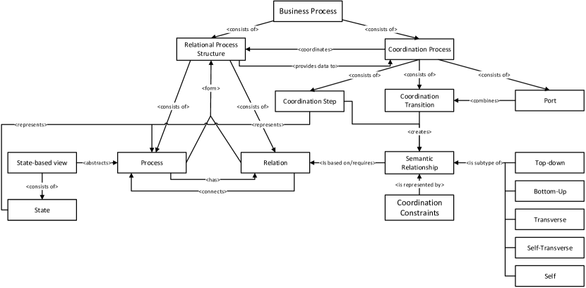
Object-aware process management is an comprehensive approach for managing data-centric processes (Künzle and Reichert, 2011). The core of object-aware process management is presented as a meta-model in Figure 5. Object-aware process management describes business processes in terms of interacting processes, e.g., object lifecycles, with the goal of providing better support for data and better flexibility. The business process only emerges through interactions between processes, and this requires coordination for guiding the business process towards a meaningful goal. Note that the meta model is intended as an overview and only represents a simplified view and does not convey all details of either the design-time or the run-time.
The coordination approach of object-aware process management consists of three concepts: relational process structures capture and track process types and their relations. Semantic Relationships use these relations for describing constraints for coordinating the interactions between processes. Coordination processes are used for concretely specifying semantic relationships and enforcing these constraints at run-time, relying on the information provided by the relational process structure. Moreover, for obtaining only the relevant information coordinating the processes, these processes are abstracted using a state-based view.
The concepts that constitute and support a coordination process are inextricably linked to each other, which necessitates mutual references and forward references in the formal definitions for completeness. The formal definitions mirror the implementation of the concepts and do not contain cyclic dependencies, but simply mutual references for navigating the resulting graph. Consequently, formal definitions may mention concepts and entities that will only be defined later in this section. Still, the introduction of concepts and entities follows a logical top-down manner despite the forward references. The intention is to keep this background section as concise as possible while still conveying the essential information. The (mutual) references are implicitly resolved using a globally unique identifier (GUID) for each entity, omitted in all definitions for conciseness. Furthermore, as this article is part of a larger body of work in context of the PHILharmonicFlows project, the formal definitions are kept consistent in every article.
This section is concerned exclusively with the design-time of coordination processes and otherwise the design-and run-time of other concepts as far as required for understanding Sections 4-6. Figure 6 gives a brief over coordination process design-time entities introduced in this section and their relationship to each other.
3.1 Basics
Coordination processes and their related concepts operate on a strict distinction between design-time and run-time entities. A design-time entity is designated as a type (formally superscriptT), whereas run-time entities are instances (formally I). “Entity” is used as an umbrella term comprising all types and instances defined in the following. For the sake of brevity, when referring to entities without a type or instance superscript or word member, e.g., just process instead of process instance, this means that a statement applies to both types and instances. By convention, instances are created by instantiating a type. The dot (.) represents the member access operator. The symbol signifies the subtype relation, i.e., is a subtype of is written as . Again, by convention, any set is denoted by a capital letter, whereas an element of the set is denoted with the same lowercase letter. The concepts that constitute and support a coordination process are inextricably linked to each other, which necessitates mutual references and forward references in the formal definitions for completeness. For sake of clarity, formal definitions are presented in a top-down manner.
Definition 1 (Process Type)
A process type has the form where
-
•
refers to relational process structure to which this process type belongs (cf. Definition 6)
-
•
is the unique identifier (name) of the process type
-
•
is a process model specification not publicly visible
-
•
is a publicly visible state-based view mapped to (cf. Definition 3)
While objects and their lifecycle processes have provided the initial motivation for coordination processes, objects with lifecycle processes are not a prerequisite for coordination processes to work. Therefore, a generalized notion of process is used that may represent, in principle, any kind of process model specification, except for a coordination process. Object lifecycle processes are just one example of a process . For the purpose of coordination processes and their operational semantics, the paradigm and modeling language in which processes are specified is unimportant. Consequently, a process may be an object-aware process or a process that is specified using BPMN 2.0 (Object Management Group, 2011). Consequently, no formal definition of is provided. Instead, a state-based view provides an abstraction level over the actual process specification (Steinau et al, 2019), which is used by a coordination process.
Thereby, every process to be coordinated is partitioned into different states that provide significant meaning for process coordination. State-based views enable a coordination process to be paradigm-agnostic, i.e., processes from any paradigm or even different paradigms may be coordinated. This applies to both type and instance levels.
Definition 2 (Process Instance)
A process instance has the form where
-
•
refers to the process type from which has been instantiated (cf. Definition 1)
-
•
refers to the relational process instance structure to which this object instance belongs (cf. Definition 7)
-
•
is the unique identifier (name) of the process instance. Default is
-
•
is a process instance specification not publicly visible
-
•
is a publicly visible state-based view mapped to (cf. Definition 3)
State-based views partition a process specification into distinct and non-overlapping states (cf. Definition 3). More precisely, a state-based view is an abstraction over , the actual process specification, mapping elements of to states of the state-based view so that each process element (e.g., an activity) belongs to exactly one state (cf. Figure 7)(Steinau et al, 2019). States are used to indicate the progress of the underlying process . State-based views are virtually identical for design-time and run-time, indicated by the missing superscript.
Definition 3 (State-based View)
A state-based view has the form where
- •
-
•
is a set of states
-
•
is a set of transitions
-
•
is a set of backwards transitions .
States are connected with directed edges denoting state transitions. At run-time, an active state of a process signifies its current execution status; the active state is determined by , e.g., the currently executed activity is mapped to . As states are an abstraction over executable elements, e.g., activities, for the sake of abstraction, the term executing a state is used to refer to work being done within the state, e.g., executing the activities in the state. Only one state may be active at a given point in time. As a consequence, branching state transitions categorically implement an exclusive choice semantics, i.e., states may be mutually exclusive regarding activation. This does not prohibit parallel execution of activities, as parallelism may still occur within a state. Note that this is in addition to the concurrent or parallel execution of processes. As only one state may be active, in case of mutually exclusive states, non-active states are denoted as skipped. Furthermore, state-based views may include backwards transitions that allow re-activating a previous state , i.e., is a predecessor of the currently active state . For changing a state, transitions and backwards transitions require an explicit commitment per default, e.g., a user or system must explicitly commit the activation of the transition. Figure 7 shows state-based views of the processes referenced in Example 1.
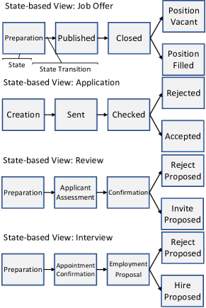
States and their transitions are, by default, the only entities that are publicly visible to an outside observer of a process. The state transitions and the active state are driven by . Despite the simplistic specification, state-based views capture the essentials of a process in regard to process coordination. In addition, if desired, state-based views may introduce additional process properties, e.g., specific data attributes that may subsequently be used for process coordination.
Generally, processes may be interconnected by relations. A relation represents a connection between two processes, indicating one or more dependencies between them, i.e., multiple coordination constraints can be defined over the same relation. A relation type (cf. Definition 4) and relation instance (cf. Definition 5) are defined as follows:
Definition 4 (Relation Type)
A relation type represents a many-to-many relation between two processes and has the form where
-
•
refers to the source process type (cf. Definition 1)
-
•
refers to the target process type (cf. Definition 1)
-
•
is an upper bound on the number of process instances with which may be related. Default:
-
•
is a lower bound on the number of process instances with which may be related. Default:
-
•
is an upper bound on the number of process instances with which may be related. Default:
-
•
is a lower bound on the number of process instances with which may be related. Default:
As a relation type represents a many-to-many relationship, four bounds are needed to have restrictions on both source and target sides. By choosing appropriate bounds, a relation type may represent one-to-many and one-to one relationships as well.
Definition 5 (Relation Instance)
A relation instance has the form where
Relation instances always have exactly one source and one target process instance, as one-to-many or many-to-many relationships are comprised of multiple relation instances (cf. Figure 8). In particular, two processes may be related by a transitive relation, i.e., a path of relations exists connecting one process with another. Contrary to, for example, Entity-Relationship-Diagrams, relations are directed, which serves various purposes, among them the definition of semantic relationships (cf. Section 3.3). For any process type or instance , two sets are maintained in regard to relations: is the set of incoming relation instances for a process instance , i.e., , and , which is defined analogously for outgoing relations. These sets allow realizing some efficiency optimizations in coordination process execution and are therefore mentioned for accuracy.
3.2 Relational Process Structures
Relational Process Structures provide a major building block for solving Challenge 2 Complex Process Relations (cf. Section 2.2). Moreover, they are a factor in solving Challenge 3 Local Contexts and Challenge 4 Immediate Consistency (cf. Sections 2.3 and 2.4). At design-time, a relational process type structure captures all processes and their relations (cf. Definition 6) (Steinau et al, 2018b). Formally, relational process type and relational process instance structure (cf. Definition 7) are defined as follows:
Definition 6 (Relational Process Type Structure)
A relational process type structure has the form where
Definition 7 (Relational Process Instance Structure)
A relational process instance structure has the form where
-
•
refers to the relational process type structure from which has been instantiated
-
•
is the set of process instances (cf. Definition 2)
-
•
is the set of relation instances (cf. Definition 5)
Relation types (and by extension, relation instances) that belong to relational process structure only exist between processes in . Creating a new relation between two process instances is referred to as linking process instances. The new process instance and the new relation are then added to the respective sets of the relational process structure the existing process instance belongs to.
At run-time, the purpose of the relational process instance structure is to track and capture every creation and deletion of processes and relation instances, enabling full process relation awareness (Steinau et al, 2018b). Process instances may be added dynamically during run-time to an existing relational process instance structure, each creating a new relation between the process instance to be added and a process instance that is already part of the relational process instance structure.
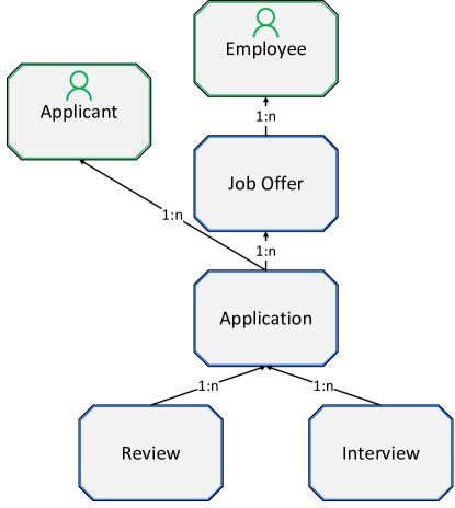
A coordination process can query the relational process instance structure to obtain up-to-date information about processes and their relations. Figure 9 shows an example of a relational process type structure in context of the running example.
A coordination process can query the relational process instance structure to obtain up-to-date information about processes and their relations.
The formal notation is used to signify a (transitive) directed relation from process to process . The directed relation between processes induce a hierarchy in a relational process structure. In this context, the terms lower- and higher-level become important. For illustration, is denoted as a higher-level process in respect to process , as there is a directed relation from to (cf. Figure 9). Transitively, is also a higher-level process to and . Analogously, and are lower-level processes in respect to process . This terminology applies to transitive relations as well. The process types and are user process subtypes concerned with representing users, relevant for authorizations and permissions in object-aware process management (Andrews et al, 2017).
For the purpose of coordination processes, each process is required to know all its related processes, specifically, its lower- and higher-level processes. In order to avoid computationally expensive queries every time lower- or higher-level instances are needed, the relational process structure maintains two sets per process instance : for all lower-level instances and for all higher-level instances. These sets are kept up-to-date as the process structure evolves, providing a performance benefit to process coordination (Steinau et al, 2018b).
Altogether, relational process structures allow for a coordination approach to gain full knowledge over processes and their relations, and thus enable fine-grained process coordination. Relational process structures represent one foundation for coordination processes (cf. Figure 1).
3.3 Semantic Relationships
Semantic relationships are means to specify coordination constraints at a high level of abstraction (Steinau et al, 2017). A coordination constraint is a formal or informal statement describing one or more conditions or dependencies that exist between processes. For example, the statement “An application may only be accepted if three or more reviews are positive” is a coordination constraint. In essence, process coordination is tasked with formally capturing and enforcing coordination constraints. Other coordination approaches, e.g., BPMN choreographies (Object Management Group, 2011), choose messages to express the necessary interactions between the processes to be coordinated. However, due to complex process relationships and large numbers of process instances, defining messages in a procedural manner is cumbersome. This is especially true for larger relational process structures. Specifying individual messages also negatively impacts the fulfillment of Challenge 1 Asynchronous Concurrency. A process modeler has to ensure asynchronous concurrency manually when specifying messages, requiring large efforts.
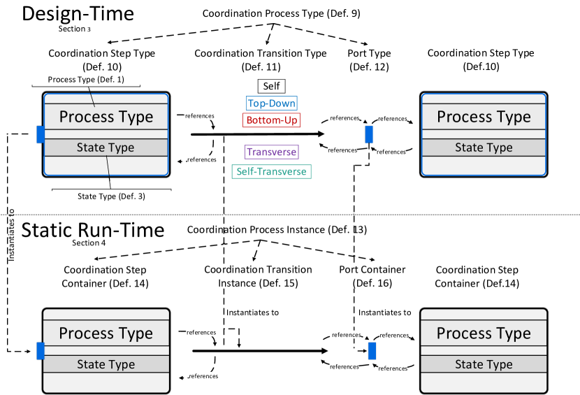
A coordination constraint must be expressed in terms of semantic relationships for its use in a coordination process. A semantic relationship describes a recurring semantic pattern inherent in the coordination of processes in a one-to-many or many-to-many relationship (cf. Table 1). As one example of a pattern, several process instances may depend on the execution of one other process instance. For a proper representation of coordination constraints, the combination of multiple different semantic relationships might become necessary. Moreover, a semantic relationship may only be established between processes if a (transitive) relation within the relational process structure, i.e., a dependency, exists between these processes. Figure 10 illustrates the types of semantic relationships between different processes in the running example.

| Name | Description of the semantic relationship |
|---|---|
| Top-Down | The execution of one or more lower-level processes depends on the execution status of one common higher-level process. |
| Bottom-Up | The execution of one higher-level process depends on the execution status of one or more lower-level processes of the same type. |
| Transverse | The execution of one or more processes is dependent on the execution status of one or more processes of different type. Both types of processes have a common higher-level process. |
| Self | The execution of a process depends upon the completion of a previous step of the same process. |
| Self-Transverse | The execution of a process depends on the execution status of other processes of the same type. All processes have a common higher-level process. |
Semantic relationships are specified at design-time in the context of a coordination process. Formally, a semantic relationship is defined as follows.
Definition 8
A semantic relationship has the form where
-
•
is the identifier of the semantic relationship,
-
•
is an expression, configuring in case of
-
•
is a set of state types in case of .
-
•
refers to the common ancestor of in case of
Semantic relationships are always defined between two (not necessarily different) types of processes. Different semantic relationships, determined by the identifier , signify different basic constraints (cf. Table 1). One of the outstanding features of semantic relationships is that the appropriate semantic relationship between processes can be automatically inferred from a relational process structure. This is possible as the direction of the relations directly implies certain semantic relationships between process types (Steinau et al, 2018b). This is exemplified in Example 8.
Example 8 (Top-Down and Bottom-Up Semantic Relationships I)
Consider Figure 9: A top-down semantic relationship can be established from to an , as there is a relation from to . Additionally, a bottom-up semantic relationship can be established from to a . The direction of the connection and the direction of the relation determine directly the type of semantic relationship. Note also that one relation supports establishing multiple semantic relationships on top.
The execution status referred to in Table 1 is represented by the state-based view of the process (cf. Section 3). At run-time, each semantic relationship has a logical value to indicate whether or not it is satisfied; Boolean operators may be used to express more complicated coordination logic involving more than one semantic relationship. Semantic relationships have been designed with Challenge 1 Asynchronous Concurrency in mind. The details on how Challenge 1 is fulfilled are presented in Sections 5-7.
Semantic relationships feature an expression in case of a bottom-up, transverse, or self-transverse semantic relationship. Top-down semantic relationships feature a state set. Self semantic relationships cannot be configured and do not possess an expression or a state set (cf. Definition 8). Instead, they may be addressed collectively by using the umbrella term coordination condition. A coordination condition modifies the basic semantics of the semantic relationship (cf. Table 1), which is needed to customize a semantic relationship to specifically represent a coordination constraint. Details on the coordination conditions can be found in (Steinau et al, 2018a).
3.4 Coordination Process Types
Coordination processes are a generic concept for coordinating interdependent processes by expressing coordination constraints with the help of semantic relationships, which are then enforced at run-time (Steinau et al, 2018a). The concept allows specifying sophisticated coordination constraints for vast structures of interrelated process instances with an expressive, high-level graphical notation using a minimum number of modeling elements.
A coordination process type is a design-time entity, which is represented as a directed, connected, and acyclic graph that consists of coordination step types, coordination transition types, and port types (cf. Figure 11). A formal definition of coordination process types is presented in Definition 9. Figure 12 shows the coordination process type for the processes of the running example, which ensures the correct enactment of the overall recruitment business process.
Definition 9 (Coordination Process Type)
A coordination process type
has the form
where
-
•
refers to the process type to which the coordination process type belongs
-
•
is a set of coordination step types (cf. Definition 10)
-
•
is a set of coordination transition types (cf. Definition 11)
-
•
is a set of port types (cf. Definition 12)
Coordination steps are the vertices of the graph referring to a process type as well as to one of the states of its state-based view , e.g. and state . For the sake of convenience, a coordination step is addressed with referenced process type and state in the form of :, e.g. :. A formal definition for coordination steps is presented in Definition 10.
Definition 10 (Coordination Step Type)
A coordination step type
has the form
where
-
•
refers to the coordination process type (cf. Definition 9)
-
•
refers to a process type (cf. Definition 1)
-
•
refers to a state type belonging to , i.e., (cf. Definition 3)
-
•
is a set of outgoing coordination transition types (cf. Definition 11)
-
•
is a set of port types (cf. Definition 12)
A coordination transition is a directed edge that connects a source coordination step type with a target coordination step type (cf. Figure 12 and Definition 11).
Definition 11 (Coordination Transition Type)
A coordination transition
type has the form
where
-
•
refers to the source coordination step type (cf. Definition 10)
-
•
refers to the target port type (cf. Definition 12)
-
•
is a semantic relationship between and
More precisely, connects to one of multiple ports that are attached to . A formal definition of ports is shown in Definition 12
Definition 12 (Port Type)
A port type has the form where
-
•
refers to the coordination step type to which this port type belongs (cf. Definition 10)
-
•
is the set of all incoming coordination transitions (cf. Definition 11)
By creating a coordination transition between source step and target step , a semantic relationship is created as well. Conceptually, a semantic relationship is attached to a coordination transition. With the relations from the relational process structure and the definitions of semantic relationships (cf. Table 1), the identifier can be automatically derived. The identifier determines which semantic relationship is established between the process types referenced by the two coordination steps.
Example 9 (Top-Down and Bottom-Up Semantic Relationships)
Connecting : with : constitutes a top-down relationship (cf. Figure 12). The sequence in which the steps occur is important for determining the type of semantic relationship. By connecting : with :, a bottom-up semantic relationship is established instead, as is a lower-level process type of .
As coordination transitions represent coordination constraints with semantic relationships, coordination constraints depend on previous constraints for fulfillment. In Example 8, activating : requires at least one in state , which in turn requires : to be activated. The coordination constraint between : and : depends on the constraint between : and :. Therefore, coordination process graphs must be acyclic, otherwise cyclic dependencies and, therefore, deadlocks are possible. Consequently, the acyclicity of coordination processes is not a restriction of expressiveness, but a requirement for correctness.
Moreover, a coordination process is not required to coordinate all processes at every point in time. Depending on the coordination constraints, only the processes and states that are necessary for these constraints need to be modeled and are therefore subject to coordination. States and processes that do not occur in a coordination process model are not constrained in their execution by process coordination. Consequently, coordination process allow for a high degree of freedom in executing processes by only providing coordination when absolutely required.
Ports allow realizing different semantics for combining semantic relationships (Steinau et al, 2018a). Connecting multiple coordination transitions to the same port corresponds to AND-semantics, i.e., all semantic relationships attached to the incoming transitions must be enabled for the port to become enabled as well. Enabling a port also enables the coordination step, allowing the state of the coordination step to become active. Generally, at least one port of a coordination step must be enabled for the coordination step to become enabled as well. Consequently, connecting transitions to different ports of the same coordination step corresponds to OR-semantics.
A coordination process is a directed, acyclic graph which possesses exactly one start coordination step and a finite set of end coordination step types . The notions of start and end coordination step apply equally to types and instances. A start coordination step type has no port types and consequently no incoming transitions, i.e., . Analogously, an end coordination step has no outgoing transitions, i.e., . Coordination process enactment begins at the start step and terminates after reaching an end step .
A coordination process is attached to a particular process type within the relational process structure. This process type is denoted as a coordinating process type . Note that is a short-hand notation for a process being a coordinating process type, i.e, , and does not signify one specific process. There may be many processes in a relational process structure that are coordinating processes, i.e., , as many coordination processes may be used to coordinate the same relational process structure . The notion of coordinating process also applies at the instance level, i.e., there may be one or more coordinating process instances. For the running example (cf. Example 1), is designated as the coordinating process type.
The scope of a coordination process determines which processes it needs to coordinate, in relation to the coordinating process type . In general, the scope is defined as all lower-level process types of the coordinating process type, which includes itself. The processes contained in are called the coordinated processes. In the running example, the coordination process is responsible for coordinating , , , and . Coordinating process type and the concept of scope serve for dealing with large process structures, coordinated by multiple coordination processes.
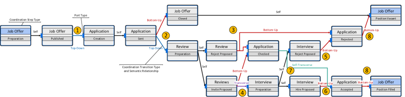
In the following, this paper gives a rundown of the coordination process (cf. Figure 12) of the running example (cf. Example 1) and the most important coordination constraints. Encircled numbers \raisebox{-.9pt} {n}⃝ represent points of interest in Figure 12.
Example 10 (Coordination Process Rundown)
Any process begins enactment in the start state , represented by the start coordination step type of the coordination process. The outgoing self semantic relationship signifies the transition of the to state . Then, Coordination Constraint 1 is represented using a top-down semantic relationship \raisebox{-.9pt} {1}⃝.
Coordination Constraint 1
An application may only be created as long as the corresponding job offer is published.
After coordination step type :, a self semantic relationship allows an to transition to state . When in state , may be created for the (cf. Coordination Constraint 2), again represented by a top-down semantic relationship \raisebox{-.9pt} {2}⃝. Multiple lower-level processes () depend upon the execution status (state ) of one higher-level process (the ) (cf. Table 1).
Coordination Constraint 2
An application may only be reviewed once it has been sent to the company.
Moreover, at least one in state allows a to reach state (cf. Coordination Constraint 3). For representing the coordination constraint, a bottom-up semantic relationship is established between coordination step types : and : \raisebox{-.9pt} {2}⃝. It is a bottom-up semantic relationship as is a higher-level process of (cf. Table 1).
Coordination Constraint 3
A job offer may be closed after at least one application has been received.
Coordination Constraint 4 determines when may reach state or when may
be created. Rejection is handled by a bottom-up semantic relationship between coordination step types : and : \raisebox{-.9pt} {3}⃝. The precise semantics of the bottom-up semantic relationship is accomplished with an expression (cf. Definition 8).
Coordination Constraint 4
An interview with the applicant may only be performed if at least three reviews or a simple majority of reviews are in favor of the applicant. Applications for which this is not the case must be rejected.
In case of favorable , a transverse semantic relationship is established between : and : \raisebox{-.9pt} {4}⃝. depend on in the context of a particular (cf. Table 1). The serves as the common ancestor of the transverse semantic relationship (cf. Definition 8). The precise semantics of the transverse semantic relationship are again accomplished with an expression (cf. Definition 8). In case of unfavorable reviews, the must be rejected. : is connected to a second port of coordination step : \raisebox{-.9pt} {5}⃝.
This constitutes OR-Semantics, as an may be rejected because of unfavorable or unfavorable . After have been created and conducted, another assessment of the applicant is accomplished. In case of favorable , the may be (cf. Coordination Constraint 5). Therefore, a bottom-up semantic relationship is established between : and : \raisebox{-.9pt} {6}⃝.
Coordination Constraint 5
At least one interview or a simple majority of interviews must be in favor of the applicant before the applicant can be accepted for the job offer
In addition to the bottom-up semantic relationship representing Coordination Constraint 5, another coordination constraint affects the acceptance of an
(cf. Coordination Constraint 6).
Coordination Constraint 6
Only one applicant may be accepted for a job offer.
For Coordination Constraint 6, depend on other , hence a self-transverse semantic relationship is established \raisebox{-.9pt} {7}⃝ (cf. Table 1). The self-transverse semantic relationship permits only one to reach state , whereas other are blocked. The self-transverse semantic relationship connects to the same port of : as the previous bottom-up semantic relationship. This represents AND-semantics, as both Coordination Constraints 5 and 6 need to be fulfilled simultaneously.
Finally, Coordination Constraint 7 determines under which conditions a : may terminate.
Coordination Constraint 7
The job offer is successfully completed when an applicant has been found. If no suitable applicant is found, the job offer ends with status “Position vacant”.
The representation of Coordination Constraint 7 must be split into two semantic relationships. One bottom-up semantic relationship established between : and : represents the case where no suitable applicant could be found. A second bottom-up semantic relationship between : and : represents the opposite case, i.e., a suitable applicant could be found \raisebox{-.9pt} {8}⃝.
How a coordination process can fulfill its role and enforce these coordination constraints at run-time is explained in the subsequent sections. The enactment of a coordination process involves two primary components: The accurate representation of process instances, their relations, and their semantic relationships in a coordination process at run-time, and the comprehensive operational semantics to enforce the constraints imposed by semantics relationships on the coordinated process instances.
4 Enacting Coordination Processes
A coordination process model represents coordination constraints between multiple process types in terms of (multiple) semantic relationships (cf. Section 3.3). The process types to be coordinated and their relations are captured in a relational process structure (cf. Section 3.2). At run-time, multiple process instances may be created from each of these types, which then form relations to other instances. Compared to the design-time, this represents an enormous additional complexity. The specific challenges of the run-time have been discussed in Section 2. Consequently, a coordination process instance is required to deal with this complexity adequately if proper process coordination shall be provided.
One of the main ideas of a coordination process is that it may be enacted, similarly to any regular process. A coordination process is not simply a collection of coordination constraints, but the representation of constraints is done in a process-like fashion. An instance of a coordination process has a start and an end, as well as steps in between signifying important goals for process coordination. Through the enactment of a coordination process, it enforces the correct coordination constraints at the appropriate time. Furthermore, a coordination process is able to react to changing circumstances, e.g., when a new process instance emerges or existing process instances are deleted. This enactment can be split into two parts: The first part consists of the correct representation of process instances and their semantic relationships, taking Challenge 2 Complex Process Relations and Challenge 3 Local Contexts into account. Based on this representation, the operational semantics, constituting the second part, describes how the coordination process is enacted, i.e., which coordination constraint is fulfilled or not at which point in time. In the following, the general properties of run-time coordination processes are discussed.
This section is concerned with the static parts of the run-time, called the “static run-time”. Static in this context means that certain entities are instantiated once per coordination process instance and persist over the lifetime of the coordination process. Dynamic entities are instantiated and deleted conditionally and introduced in Section 5. Figure 13 gives a brief over entities introduced in this section and their relationship to each other. Further, it displays their connection to the design-time entities of Section 3.
Coordination process instances coordinate process instances captured in a relational process instance structure. For this purpose, the coordination process model is instantiated along with its coordinating process type , e.g., a coordination process instance is created along with an instance of (cf. Example 1). The coordination process instance is responsible for enforcing all coordination constraints in the context of the process instance. Formally, a coordination process instance is defined as follows:
Definition 13 (Coordination Process Instance)
A coordination process instance
has the form
where
-
•
is the coordinating process instance to which belongs (cf. Definition 2)
-
•
is a set of coordination step containers (cf. Definition 14)
-
•
is a set of coordination transition instances (cf. Definition 15)
-
•
is a set of port containers (cf. Definition 16)
The model of a coordination process type contains coordination step types , coordination transition types , and port types . By principle, a coordination step type represents multiple process instances at run-time, e.g., multiple instances are represented by an coordination step type. This has consequences for the overall instantiation of a coordination process: A coordination step type is not instantiated once per coordination process instance, but instead multiple times, depending on how many process instances of corresponding type exist in the relational process structure. Figure 14 shows an example configuration of a relational process instance structure for the running example. Accordingly, an coordination step type would create two instances representing each .
Regarding a relational process structure at run-time, the term arrangement denotes a specific substructure of the relational process structure. It is characterized by specific process instances and their concrete relations. Arrangements are defined as immutable, i.e., adding a new relation or process instance creates a new arrangement, which is consequently not identical to the first arrangement. In other words, arrangements can be thought of as snapshots of a part of the relational process structure. Note that an entire relational process structure, at a specific point in time, is likewise an arrangement.
Arrangements are connected to Challenge 3 Local Contexts, but are however not identical to local contexts. The main difference is that arrangements are precisely defined by processes and relations, and any change destroys the arrangement and creates a new one (immutability). In contrast, local contexts persists over changes of the relational process structure, i.e., linking a new to an instance creates a new arrangement, but the local context of the remains the same.
Example 11 (Arrangements and relational process instance structure)
In Figure 14, the combination of processes , , and and their relations is one example of an arrangement. Generally, Figure 14 shows a snapshot of the recruitment business process (cf. Example 1). One instance and related process instances are shown to be in various stages of processing (cf. Figure 7 for an overview of the state-based views). Specifically, two have been submitted for . More may still be sent, as the is still in state . The process instance is in the first states of processing, as its active state is and only two are linked, which have not yet reached a conclusion (states and , respectively). By contrast, already has three completed with a positive conclusion, signified by state . Because of the positive verdict, it is allowed conducting with the applicant, for whom is currently in state . This is another arrangement different from the arrangement involving .
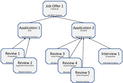
The coordination process of (cf. Figure 12) ensures that all coordination constraints are upheld during the execution of all process instances. For example, each coordination step type that represents the process type, namely :, :, :, :, and :, references each instance. A coordination step instance would be required to have a reference to process type, state type, and process instance information. As depicted in Figure 14, the relational process instance structure has two instances. In consequence, this results in ten coordination step instances, representing two instances and each of the five coordination step types. The state type and process type is however held redundantly in each coordination step instance. Note that this implies that there are groups of coordination step instances based on state type and process type information. In other words, each coordination step type corresponds to a group of coordination step instances at run-time.
In order to organize this information efficiently, the instatiation of a coordination step type follows a non-standard pattern. Instantiating a coordination step type creates two different entities:
-
1.
A coordination step container, which is instantiated exactly once with the creation of the coordination process instance and contains process and state information, representing the group.
-
2.
The actual coordination step instance, which is instantiated dynamically and represents a corresponding process instance belonging to the group.
Formally, a coordination step container is defined as follows:
Definition 14 (Coordination Step Container)
A coordination step
container has the form
where
-
•
is the coordination process instance (cf. Definition 13)
-
•
is the process type (cf. Definition 1)
-
•
is a state type of (cf. Definition 3)
-
•
is a set of coordination step instances (cf. Definition 17)
-
•
is a set of outgoing coordination transition instances (cf. Definition 15)
-
•
is a set of port instance containers (cf. Definition 16)
Coordination transition types and port types follow the same non-standard pattern. Coordination transition types create coordination transition instances, functioning as containers, and coordination components, functioning as dynamic representations of semantic relationships (cf. Definition 15). Port instances and coordination step instances are analogous to coordination step instances regarding containers.
Definition 15
A coordination transition instance has the form where
-
•
is the source coordination step container (cf. Definition 14)
-
•
is the target port instance container (cf. Definition 16)
-
•
is a set of coordination component instances (cf. Definition 19)
The instantiation of port types functions analogously to the instantiation of coordination step types. Port instance containers that contain port instances are defined as follows:
Definition 16
A port instance container has the form where
In essence, containers represent the scaffolding of a coordination process instance. Containers replicate the structure of the coordination process model at run-time and are static components, i.e., they persist over the lifetime of the coordination process instance. Within the containers, coordination step instances, coordination component instances, and port instances are located. These are dynamic components, which depend on the existence of process instances and their relations. For example, when a new process instance emerges, a new coordination step instance becomes instantiated as well, and is put into the appropriate container. In the same way, coordination step instances are deleted when the process instance is deleted. Coordination step instances, coordination component instances, and port instances are discussed in detail in Section 5. Figure 15 shows a part of a coordination process instance consisting solely of containers, with placeholders standing for the dynamically instantiated entities.
Coordination containers were introduced for technical reasons in order to maintain correct references and associations in an implementation. However, coordination containers find usage in the (real-time) monitoring of a coordination process instance, as they can be used for providing aggregated status information over the contained coordination steps and their process instances.
Coordination step containers, coordination transition instances, and port containers are the static entities of a coordination process instance. In Section 5, the dynamic entities, namely coordination step instances, coordination components, and port instances, are discussed in detail.
5 Representing Process Instances and Semantic Relationships
A coordination process instance coordinates process instances that fall within its scope in the relational process structure . More precisely, it coordinates process instances that fall within its scope and whose type is referenced by a coordination step type of the coordination process model . Process instances whose process type is not referenced by at least one coordination step type are irrelevant for the coordination process instance . Both the creation of new process instances and deletion of old process instances affect a coordination process instance. For the sake of brevity, the following examples use the creation of a new process instance or existing process instances; deletions are handled correctly as well by a coordination process instance, but are omitted in this paper. The following elaborations continue using the running example: one coordination process instance is attached to the process instance, and is responsible for coordinating the entire relational process structure (cf. Figure 14).
Whenever a new process instance is created and, hence, emerges in a relational process structure, it must first be checked whether it is to be coordinated by . To efficiently accomplish the check, a relational process instance structure maintains the set of lower level process instances for each object instance (cf. Section 3.2). If is a coordinating process type, i.e., , and the new process instance is added to of , the corresponding coordination process instance is notified of this addition. This optimized approach avoids the performance penalty of continual depth-first traversals of the relational process structure in order to recognize new instances, which contributes to fulfilling Challenge 4 Immediate Consistency (Steinau et al, 2018b).
This section is concerned with the dynamic parts of the run-time. Dynamic entities are instantiated or deleted conditionally, based on the existence of processes and relations. Figure 16 gives a brief over entities introduced in this section and their relationship to each other. Further, it displays their connection to the design-time entities of Section 3.
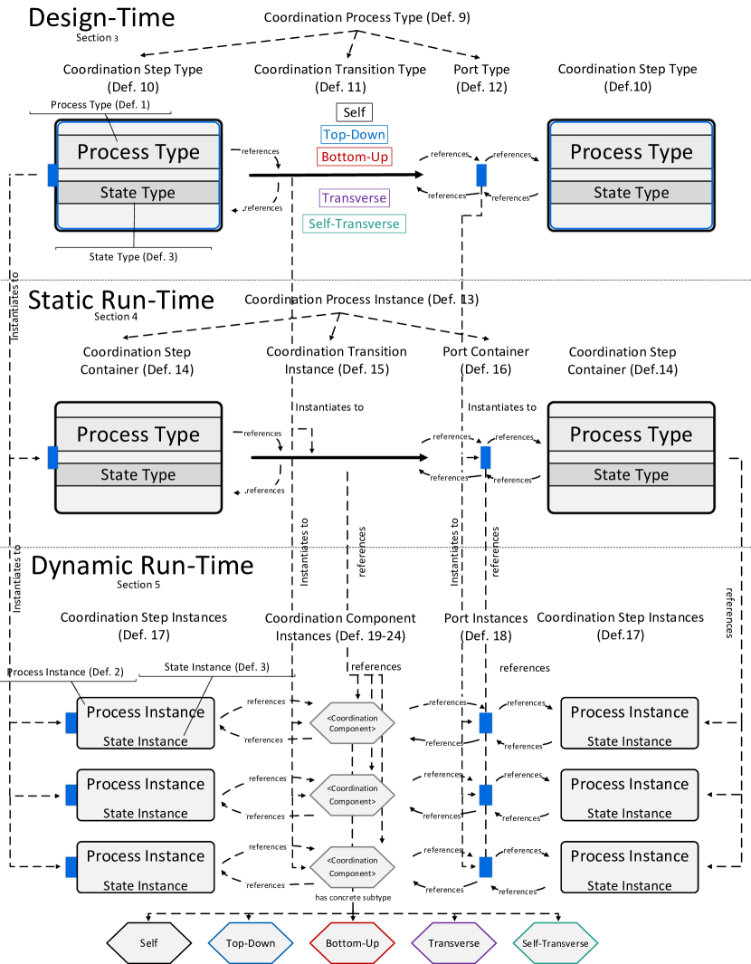
5.1 Coordination Step and Port Instances
If the new process instance needs to be coordinated by the coordination process instance, the new process instance is represented with a coordination step instance in the coordination process. Formally, a coordination step instance is defined as follows:
Definition 17 (Coordination Step Instance)
A coordination step instance
has the form
where
-
•
is a coordination step instance container (cf. Definition 13)
-
•
is a reference to a process instance (cf. Definition 2)
-
•
is a reference to a state instance belonging to , i.e., (cf. Definition 3)
-
•
is a set of outgoing coordination component instances (cf. Definition 19)
-
•
is a set of port instances (cf. Definition 18)
For each process instance , there is exactly one corresponding coordination step instance in each container . Consequently, a particular process instance may be represented by multiple coordination step instances , depending on the number of containers that reference the corresponding process type . The reason is that coordination step types not only reference a process type , but also a state type , analogous to the coordination step instance (cf. Definition 17). Consequently, a coordination step instance is created for each combination of process type and state type referenced by coordination step type in each container . The state type is important for the operational semantics of a coordination process.
The instantiation of a coordination process itself is a good example of how a process is represented by multiple coordination step instances. Coordination process types are instantiated together with their coordinating process type . By definition, a coordinating process type belongs to the scope of the corresponding coordination process, i.e., .
As such, coordinating process instance must be represented by coordination step instances. In case of the running example (cf. Example 1) and the coordination process type (cf. Figure 12), the coordination process type contains five coordination step types referencing the process type. These are the states :, :, :, :, and :. The naming scheme is chosen in this manner for simplicity. Coordination step types can be unambiguously identified by their references to and , as this combination is unique in a coordination process. At run-time, coordination step types are instantiated as containers and coordination step instances, which are referenced by using the same naming scheme : plus additional type information, e.g., coordination step container :.
Consequently, the instance is represented by five coordination step instances (cf. Figure 12). For the sake of simplicity, Figure 17 shows an excerpt of the entire coordination process. This excerpt exemplarily shows the first two coordination step containers : and : as well as the corresponding coordination step instances for . In contrast to the start coordination step instance, the coordination step instance for : possesses a port instance. Ports are used to combine semantic relationships for expressing and enforcing more complex coordination constraints. When a coordination step type bercomes instantiated, any port types defined by the coordination step model, i.e., , are instantiated as well. Formally, a port instance is defined as follows:
Definition 18 (Port Instance)
A port instance has the form where
-
•
is the corresponding port instance container (cf. Definition 16)
-
•
is the coordination step instance to which this port instance belongs (cf. Definition 17)
-
•
is the set of all incoming coordination component instances (cf. Definition 19)
For each port type , a corresponding port instance container exists at run-time. When a new coordination step instance is created, new port instances are instantiated alongside as well. The newly created coordination step instance gains exactly port instances , for a given number . The number is defined by the number of port instance containers of the corresponding coordination step container , i.e., . Each newly created port instance is additionally assigned to the respective port instance container . In short, each process instance is treated individually in a coordination process, with sets of coordination instances and respective port instances to allow for proper process coordination. This becomes an important building block towards fulfilling Challenge 3 Local Contexts and contributes to Challenge 2 Complex Process Relations.
Process instances which belong to the scope of the coordination process are adequately represented by coordination step instances and port instances. However, the most crucial part of coordination processes is still missing: the representation of the semantic relationships between process instances. Whether or not a semantic relationship can be established between two process instances is determined by the relations that exist between these instances and the coordination transitions of the coordination process type. Note that multiple different semantic relationships may be established based on the same relation between the process instances (cf. Example 12).
5.2 Semantic Relationships and Coordination Components
Semantic relationships are means to specify coordination constraints at a high level of abstraction. At design-time, semantic relationships are essentially labels for a coordination transition type. The semantic relationship indicates which coordination component instance must be created. A coordination component instance provides the necessary functionality for representing and enforcing semantic relationships between process instances at run-time. Each semantic relationship is represented by a coordination component instance whose exact properties depend on the semantic relationship (cf. Table 1). All coordination component instances are derived from a common base (cf. Definition 19), which encapsulates properties common to all coordination component instances.
Definition 19 (Coordination Component Instance)
A coordination component instance is the common base for , , , , as well as and has the form where
-
•
is the coordination component type from which has been instantiated (cf. Definition 8)
-
•
is the coordination transition instance to which is attached (cf. Definition 15)
A coordination component instance corresponds to an edge in the coordination process graph, whereas the combination of a port instance and coordination step instance corresponds to a vertex. Therefore, these elements are treated with the same vocabulary as edges and vertices, for the sake of simplicity. Coordination components have sources and targets, whereas ports and coordination steps have incoming or outgoing coordination components.
The following coordination component definitions extend with additional properties. In total, there are five unique coordination components, one for each semantic relationship (cf. Table 1). All following examples are based on the relational process structure of the running example presented in Figure 14, i.e., the relational process structure contains one instance, two instances, five instances, and one instance, as well as their respective relations.
Furthermore, establishing a coordination component between process instances is highly dynamic at run-time. Process instances may be created and deleted arbitrarily, and their relations may change. For establishing semantic relationships it is important under which circumstances a coordination component becomes instantiated (or subsequently deleted). As a semantic relationship represents coordination constraints between two process instances, its existence at run-time is logically dependent on the existence of these process instances and their relations.
Consequently, the creation of coordination components is coupled to one specific entity in a coordination process. This entity is denoted as an instantiator entity. Whenever such an instantiator entity is created, the corresponding semantic relationship is instantiated as well, i.e. a new coordination component instance is created. Depending on the type of semantic relationship, it is not always the same type of entity that is designated as the instantiator. It is noted in the formal definition of the respective coordination component instance (cf. Defs 20-24) which entity causes the instantiation of a coordination component, i.e, which entity is the instantiator.
5.2.1 Self Semantic Relationship
The simplest semantic relationship is the self semantic relationship . It represents the normal progression of a process between states. It is represented by the self coordination component (cf. Definition 20). Its purpose in a coordination process is to keep the graph connected, i.e., all coordination process graph elements are connected by transitions/edges.
Example 13 (Self Relationship)
The coordination process (cf Figure 12) has : as a start step. Coordination Constraint 1 states that may only be created once the has been .
This constraint however is not represented by a self semantic relationship and involves coordination steps : and :. Consequently, a self coordination component is used to connect the start coordination step : with the coordination step :. This mirrors normal state progression of the process (cf. Figure 7), but is necessary to be able to specify Coordination Constraint 1 (cf. Example 10). With :, the aforementioned coordination constraint may be specified using semantic relationships other than the self semantic relationship.
.
Definition 20 (Self Coordination Component Instance)
A self coordination component instance has the form where
-
•
, with defined as in Definition 19
-
•
is a coordination step instance, is instantiator (cf. Definition 17)
-
•
is a port instance with
(cf. Definition 18)
As the subtype relation holds, obtains the properties and notions defined for . A self coordination component is established between exactly one source coordination step and exactly one port instance . The coordination step of the port instance must reference the same process instance as (cf. Figure 18). As both source and target coordination step instance reference the same process instance , any of the coordination steps may be designated as instantiator. Definition 20 designates as instantiator, avoiding arbitraryness.
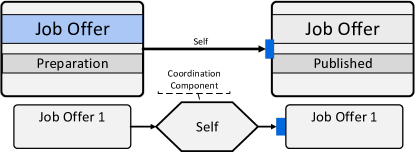
5.2.2 Top-Down Semantic Relationship
A top-down semantic relationship is employed whenever multiple process instances depend on the execution status of exactly one common higher-level process. It is represented by a top-down coordination component (cf. Definition 21).
Example 14 (Top-Down Relationship)
When a has reached state , it is permitted to create for the respective (cf. Coordination Constraint 1). This is illustrated in Figure 19. More precisely, are allowed to activate state if the top-down coordination component is active. This example is a special case, as is the start state of an . In this case, the coordination process would additionally prevent creating a relation between the and an , if the top-down coordination component was not fulfilled. In case the state is not a start state, only the state activation is prevented.
Definition 21 (Top-down Coordination Component Instance)
A top-down coordination component instance has the form where
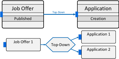
A top-down coordination component has exactly one source coordination step . On the target side, references multiple port instances and, by extension, the respective coordination step instance of and process instance . Whether or not a port instance is referenced in is determined by the relation between the respective process instances, i.e., .
Example 15 (Lower-level Instances)
The top-down coordination component for in Figure 19 references both and . As both have a relation to , they are contained in the set of lower-level instances .
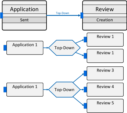
Example 16 (Instantiator)
For illustrating the instantiator, the top-down semantic relationship between : and : can be used. There are two and five in the relational process structure of the running example (cf. Figure 14). For each , a coordination step instance is created in the source container of the respective semantic relationship (cf. Figure 20). As in the source container is denoted as instantiator, corresponding top-down coordination components are instantiated as well. The are connected to the top-down coordination components according to their relations to the respective .
The instantiation of coordination components on a per-entity basis enables a fine-grained coordination. This not only applies to top-down coordination components, but also to the coordination components of other semantic relationships. However, these components have different instantiator entities. Each coordination component creates a different context for its respective instantiator, which allows coordinating two or more entities independently from each other. The coordination components hereby take the individual relations of processes into account, supporting the fulfillment of Challenge 2 Complex Process Relations. Moreover, the way coordination components are employed directly fulfills Challenge 3 Local Contexts. Each coordination component instance is a representation of such a local context.
5.2.3 Bottom-Up Semantic Relationship
Bottom-up semantic relationships are the counterpart of top-down semantic relationships. Here, the execution status of one process instance is dependent on the progress of several lower-level processes. A bottom-up semantic relationship is represented at run-time by a bottom-up coordination component (cf. Definition 22). For example, a may only reach state once an has reached state (cf. Figure 12).
Definition 22 (Bottom-up Coordination Component Instance)
A bottom-up coordination component instance has the form where
-
•
, with defined as in Definition 19
-
•
is a set of coordination step instances related to , i.e.,
(cf. Definition 17) -
•
is a port instance, is instantiator (cf. Definition 18)
-
•
is an expression copied from
A bottom-up coordination component references exactly one port instance on the target side and multiple coordination step instances on the source side. A port instance is the instantiator entity. Note that for both top-down and bottom-up coordination components, sets and , respectively, may be empty. The instantiation of the coordination component is independent from the presence of entities in these sets.
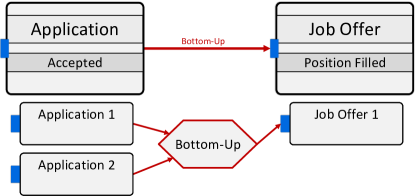
Bottom-up coordination components have an expression , which determines when the coordination component becomes fulfilled (cf. Example 17).
Example 17 (Bottom-Up Expression)
The constraint “there must be one accepted for a to reach “ requires the definition of an expression for counting the number of accepted .
For a full account on expressions refer to (Steinau et al, 2018a). The expression is copied from due to performance reasons. Multiple copies of the same expression can be evaluated simultaneously with different parameters, allowing for parallel execution. These evaluations would have to be performed sequentially in case of all bottom-up coordination component instances referencing the single expression of . In turn, an avoidable bottleneck would have been created. Therefore, expressions are copied to each bottom-up coordination component instance.
5.2.4 Transverse Semantic Relationship
Transverse semantic relationships are employed when multiple process instances of one type are dependent on multiple process instances of another type. The two process types, however, do not have a direct (transitive) relation in the relational process type structure. Instead, they are connected indirectly by a higher-level process of a third process type. Both lower level process types must have a (transitive) relation to this third process type, which is called the common ancestor in this context. At run-time, a transverse coordination component (cf. Definition 6) is used to coordinate instances of each object type.
Definition 23 (Transverse Coordination Component Instance)
A transverse coordination component instance has the form where
-
•
, with defined as in Definition 19.
-
•
is the common ancestor, is instantiator (cf. Definition 2)
-
•
is a set of coordination step instances related to , i.e., (cf. Definition 17)
-
•
is a set of port instances related to , i.e., ,
(cf. Definition 18) -
•
is an expression copied from
At both source and target side, transverse coordination components maintain sets : At the source side, a set of coordination step instances is maintained, and at the target side a set of port instances . This is different to top-down or bottom-up coordination components, where either source or target corresponds to a single entity (cf. Definitions 21 and 22). The referenced processes in both and of are determined by the common ancestor , which is a single entity. The common ancestor also serves as the instantiator entity of the transverse coordination component .
In the running example, a transverse coordination component is needed to coordinate with . For any , if a majority of are in favor of the , the respective applicant may be invited for one or more . Thus, multiple instances of one process type () are dependent on the instances of another process type (). Note that, according to the relational process type structure (cf. Figure 9), both process types do not possess a direct relation. Instead, both are lower-level process types of the process type. Consequently, instances serve as common ancestor for the transverse coordination component.
Example 18 (Common Ancestor)
Figure 22 shows transverse coordination components for the semantic relationship between : and :. As there are two , two transverse coordination components are instantiated. The connections to the source coordination step and target port instances are again determined by the relations between the process instances and the common ancestor.
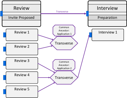
Similar to bottom-up coordination components, transverse coordination components can be configured using an expression . For example, the semantics of the transverse coordination component can be modified using to represent “A majority of reviews must be in favor of the applicant”.
5.2.5 Self-Transverse Semantic Relationship
Self-transverse semantic relationships are a variant of the transverse semantic relationship. The difference is that both process types on the source and target side are the same, giving the self-transverse semantic relationships a different purpose compared to transverse semantic relationships. Essentially, a self-transverse semantic relationship corresponds to an -out-of- choice pattern. It is represented at run-time by a self-transverse coordination component (cf . Definition 24). The self-transverse component allows process instances to reach the target state. After process instances have reached the target state, the other process instances are prevented from reaching the target state.
Definition 24 (Self-transverse Coordination Component Instance)
A self-transverse coordination component instance has the form where
-
•
, with defined as in Definition 19
-
•
is the common ancestor, is instantiator (cf. Definition 2)
-
•
is a set of coordination step instances related to , i.e., (cf. Definition 17)
-
•
is a set of port instances related to , i.e., ,
(cf. Definition 18) -
•
is an expression copied from
The formal definition of self-transverse coordination components is essentially the same as for transverse coordination components. The deciding difference is that both process types referenced in the source and target sets and are the same.
Example 19 (Self-Transverse Relationship)
The self-transverse coordination component is employed in the coordination process of the running example between : and : (cf. Figure 23). Only one may be accepted for a given , which is achieved by an appropriate expression and the self-transverse basic semantics. Once an is accepted, the remaining in state cannot reach state and must be rejected.
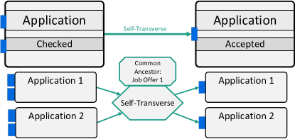
The self-transverse semantic relationship is the only typo of semantic relationship that cannot be automatically determined using the relational process structure. It shares the same characteristics as the self semantic relationship, namely the same process type as source and target. Therefore, the modeler of a coordination process has to manually choose between self semantic relationship and self-transverse semantic relationship.
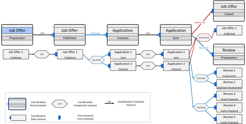
5.3 Conclusions
This section has shown how a coordination process uses the relational process structure to correctly build an interconnected graph of coordination steps, ports, and coordination components. The coordination process takes the current relational process instance structure and combines this information with the specified semantic relationships to form the graph. This graph reacts to changes in the relational process structure, i.e, the creation or deletion of process instances and relations, creating or updating coordination components and coordination steps as needed. The type and number of semantic relationships in a coordination process instance remain unchanged over the lifetime of the particular coordination process instance.
5.3.1 Fulfilling Challenge 2 Complex Process Relations and Challenge 3 Local Contexts
In regard to the challenges presented in Section 2, this representation of process instances in terms of coordination steps, ports, and coordination components solves Challenge 2 Complex Process Relations. As demonstrated in this section, coordination processes faithfully replicate the complex relationships between the numerous process instances in the relational process structure (cf. Figure 24). Semantic relationships and their respective coordination components by design take these complex relationships into account and enforce coordination constraints based on these relationships. The coordination process further adapts to changes in the relational process structure by instantiating or deleting coordination steps and coordination components as required, or changing the associations between coordination components and coordination steps according to their changing relations. This enables a high run-time flexibility when executing individual processes, changing their relations, as well as creating or deleting process instances.
Furthermore, replicating coordination components for specific coordination steps and process instances additionally create local contexts. When two coordination steps and their associated process instances are each connected to a coordination component, each coordination step is within its own local context. This allows enforcing individual constraints on each of the instances, e.g., two are in different contexts. When one is rejected and one is accepted, different coordination constraints apply to each . While the overall set of coordination constraints is, in principle, applicable to both , their different local contexts alter the relevance of specific subsets of coordination constraints. Consequently, one is treated independently from other , fulfilling Challenge 3 Local Contexts.
6 Markings and Process Rules
Described in the most general terms, coordination processes must enforce coordination constraints between different types of processes. As the processes to be coordinated are represented by a state-based view, coordination constraints essentially determine whether a state of a coordinated process is permitted to activate at a given point in time. This, in turn, is determined by the active states of other, related processes involved in the respective coordination constraint.
Example 20 (Application Creation)
An may only be created when the corresponding is in state .
Coordination processes may express coordination constraints by using combinations of semantic relationships. Semantic relationships, represented as coordination components, are connected to coordination steps and ports, which represent the process instances. Section 5 has shown how a coordination process uses the relational process structure to correctly build an interconnected graph consisting of coordination steps , ports , and coordination components . The coordination process instance takes the current relational process instance structure and combines its information with the specified semantic relationships to form the graph. This graph reacts to changes in , i.e, the creation or deletion of process instances and relations, creating coordination components and coordination steps as needed. What is still missing is a mechanism to react to the state changes of the process instances, i.e, to the process in the relational process instance structure being executed. Because of the coordination constraints, these state changes may have impact on the enactment of other process instances.
A coordination process detects when the active state of the process instances changes within its scope, and evaluates all coordination constraints affected by this change. In the end, this evaluation results in the coordination process permitting new states to become activated, or denying other states activation. Hereby, coordination processes operate according to the blacklist principle: An action is allowed by default unless a coordination constraint specifically prevents it. This allows for a high degree of flexibility when executing the coordinated processes, contributing to the fulfillment of Challenge 1 Asynchronous Concurrency.
The purpose of the operational semantics of a coordination process is to correctly evaluate and enforce the coordination constraints specified in a coordination process.
6.1 Coordination Step and State Markings
The execution status of coordinated processes, i.e., the active state of a process instance , changes far more often than the relational process structure, i.e, the operational semantics must react to state changes more often than, for example, to the emergence of a new process instance.
Example 21 (State Changes)
Consider the relational process structure from Figure 14. There are two , i.e., with active state and with active state . To each belong several and , each having their own active states. has and with active states and , respectively. has three with active state and one with active state . According to Figure 7, for each process instance in the relational process structure to have reached current status, at least 16 state changes must have occurred, but only 8 new process instances have emerged. Moreover, as no applicant has been found yet, more state changes are likely to occur when the processes are further enacted. This is because few of the process instances are yet in an end state.
Section 5 describes how process instances and relations are captured in a coordination process. However, coordination constraints are not only influenced by processes and their relations, but also by their execution status, i.e, the active state of the processes. Therefore, the combination of execution status and process relations determines whether a coordination constraint is fulfilled in a coordination process. This combination is represented in a coordination process by using markings for its constituting entities. Each entity, e.g., coordination component or port, is assigned a marking that indicates its current status. Formally, Definitions 13-19 are extended (cf. Definition 25).
-
•
is the marking of the entity , where
Each marking possesses a specific meaning for each entity type. The conditions under which the marking is applied varies between entity types. Table 2 summarizes the markings and their meanings for the coordination step instance . Note that the textual definitions of all markings (cf. Tables 2-5) are abstracted the full formal definitions used in the implementation of the coordination process approach, but convey the general intentions behind the marking. The full formal definitions are required to deal with numerous special cases to guarantee a fully operational coordination process, which for reasons of comprehensibility have been reduced to their essentials in this paper.
| Marking | Description |
|---|---|
| The coordination step has not yet been reached, i.e. none of its ports is active. The corresponding state is not skipped. | |
| A change has been triggered, requiring a reevaluation of the coordination step marking. | |
| An attached port has become active. The corresponding state may be activated, but the state is not yet active. | |
| The corresponding state is activated or confirmed and an attached port is active or completed. | |
| Either the state is skipped or all attached ports are eliminated. |
A coordination step is the only entity in a coordination process that interacts directly with the state-based view of the coordinated processes. The marking of a coordination step directly influences state marking of process , whereas vice versa marking directly influences marking . Consequently, a state in a state-based view references all corresponding coordination step instances of a coordination process where . Having coordination steps as the only entity directly interacting with state-based views fosters a loose coupling between a coordination process and the coordinated processes.
State-based views also operate on a markings-based semantics. The active state signifies the state that is currently executed; there always has to be exactly one state marked as . In case the process has finished executing, the end state remains marked as . Other markings show whether a state waits to be executed, was executed, or cannot be executed anymore due to a preceding decision branching. Table 3 gives a full overview over state markings and their meaning.
| Marking | Description |
|---|---|
| The state has not been executed yet. A predecessor state is activated. | |
| The activation of a state is blocked by an unfulfilled coordination constraint. | |
| The state is currently active. | |
| The state has been successfully executed. A successor state is activated. | |
| The state can no longer be executed. A state on an alternative branch is activated. |
If a state of a process is referenced in a coordination process, i.e., , the marking of a corresponding coordination step instance influences the marking of the state . This enables the enforcement of coordination constraints regarding the coordinated processes. Coordination processes and the expressed coordination constraints therefore may restrict the behavior of coordinated processes. For example, a state may switch directly from marking to if a state transition is triggered and no coordination process is involved. If a coordination process is involved, and if the coordination step instance is not , the resulting marking will be .
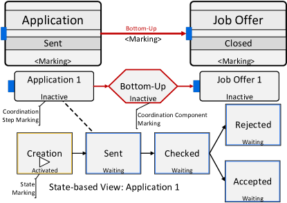
Example 22 (Inactive Coordination Step)
Figure 25 shows an example of coordination step : that coordinates state of process instance . State is currently marked as ; the start state of , i.e., state , is marked as . Currently, activation of state is prevented, as coordination step : is marked as .
Coordination step containers and coordination transition instances have markings as well. This is indicated by including placeholder markings <Marking> in the respective graphical elements (cf. Figure 25). This intends to show that these markings exist, but their specific value is irrelevant in the current context. Port containers have markings as well, which are omitted for space reasons.
In Figure 25, if the state transition from to is triggered as is executed, the coordination process prevents the immediate activation of state due to coordination step : being marked as . In other words, one or more coordination constraints (not depicted in Figure 25) prevent state from activation. In consequence, state does not receive marking , but instead is marked as . This situation is shown in Figure 26. The marking of state stops the execution of the process until the coordination constraints are fulfilled, i.e., until the coordination step becomes marked as .
This, in turn, is determined by the incoming coordination components of the coordination step instance. Whether or not the incoming coordination components can be fulfilled is determined by the coordination condition of the respective coordination component . In other words, the selection which incoming coordination component instance becomes is not made by their source coordination steps .
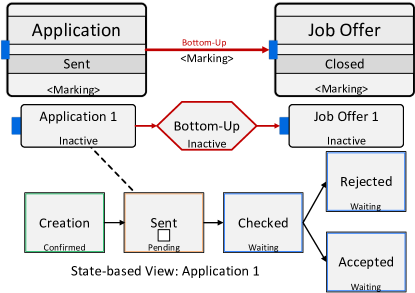
It is now assumed that, due to a change in the relational process structure, the incoming coordination constraints of : become fulfilled. This means the incoming coordination components of coordination step : and its ports, which represent the coordination constraints, allow the coordination step to be marked as (cf. Figure 27).
Immediately after coordination step : is marked as , the new status is propagated to the coordinated process instances and states, i.e., to state of . In turn, state can be activated as well, allowing the execution of to continue. In this case, the state might be activated before the corresponding coordination constraints have been fulfilled. Reaching a state before the corresponding coordination constraints permit its activation, as shown here, is denoted as state-first activation, as opposed to coordination-first activation. Note that state-first activation involves an intermediate blocking of process enactment, signified by marking . Coordination-first activation will be discussed later in this section.
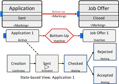
As state of has received marking , another marking change becomes necessary. According to the definition of marking (cf. Table 2), both conditions are fulfilled, i.e., ports are active and the referenced state is . Consequently, coordination step : must be marked as . Marking coordination steps as has a profound impact on its outgoing coordination components and, by extension, subsequent ports and other coordination steps. Marking changes of coordination component instances and port instances are explored in the Section 6.2.
6.2 Coordination Component and Port Markings
Coordination component instances represent semantic relationships at run-time, where each has different basic semantics (cf Section 1). When fulfilled, the referenced state of the target coordination step may become activated, otherwise the state is prevented from activation or must be skipped when the target coordination step becomes marked as . The indication whether a semantic relationship is fulfilled is determined through the markings of the corresponding coordination component (cf. Table 4). More specifically, a semantic relationship is fulfilled when the coordination component has marking .
| Marking | Description |
|---|---|
| None of the source coordination steps is completed. | |
| A change has been triggered, requiring a reevaluation of the marking of the coordination component. | |
| At least one of the source coordination steps is completed and the coordination component condition is not fulfilled. | |
| At least one of the source coordination steps is completed and the coordination component condition is fulfilled. | |
| Either all source coordination steps are eliminated or the coordination component cannot be fulfilled. |
Generally, coordination component instances become fulfilled in order from start step to end step of the respective coordination process. That means a prerequisite for fulfilling a coordination component is a path of completed coordination components leading from the start of the coordination process to the yet unfulfilled coordination component. Therefore, it may be concluded that this path exists if the source coordination step instance is marked as . This conclusion is based on the definition of coordination component markings and (cf. Table 4). It can be proven inductively that each predecessor coordination component must have been fulfilled at one point, i.e., been marked as , in order for the source coordination step instance of the current coordination component instance to be marked as .
By default, coordination components are marked as , indicating that the coordination component may still be fulfilled. Regarding the meaning, the marking for a coordination component instance is analogous to the marking for a state (cf. Table 3).
Example 23 (Completing Coordination Step Instances)
Figure 28 shows the marking of the coordination step as well as the marking of the bottom-up coordination component.
Coordination components that are connected to the same source coordination step are all marked as upon marking the coordination step instance as . This is due to the fact that any coordination component requires the completion of all previous coordination components as well, i.e., the coordination components that are on the path from the start coordination step of the coordination process to the source coordination step . In consequence, each outgoing coordination component instance must be allowed to become fulfilled.
This basically constitutes AND-split semantics, as known from, for example, BPMN 2.0. AND-split semantics for outgoing coordination components enables the fulfillment of all the subsequent coordination components. Whether or not the coordination components can be fulfilled is determined solely by the coordination condition of the respective coordination component . In other words, the selection which outgoing coordination component instances become is not done by the source coordination step . Consequently, there is no counterpart to XOR-split or OR-split semantics in a coordination process, as these are not required or achieved by different means.

Example 24 (Unfulfilled Coordination Component Instance)
The process is however not yet allowed to activate state (cf. Figure 28). The associated coordination step and its attached port are both still marked as . In order to change that, the bottom-up coordination component is required to be marked as , which, in turn, depends on whether or not the coordination component condition (cf. Table 4) is fulfilled.
For a bottom-up coordination component, the coordination condition is an expression with a Boolean return value (cf. Definition 22). The concrete expression that has been defined for the coordination component from Figure 28 is . The function counts the number of coordination steps in , for which the referenced state is . Function works analogously for state marking . The coordination step count must be at least 1 for to be fulfilled, i.e., to mark as . In other words, at least one must be in state or must have progressed to a subsequent state.
Example 25 (Coordination Component Fulfillment)
The evaluation of expression is triggered upon marking as . As contains exactly one coordination step () being marked as , is fulfilled and is immediately re-marked as .
The evaluation of is not only triggered by becoming marked as . Numerous changes within the coordination process can affect , including, but not limited to, other marking changes of coordination steps in or the emergence or deletion of processes and their associated coordination steps. Generally, each of these changes may affect the fulfillment of any coordination component and the associated coordination condition. Furthermore, changes may also revert a previous fulfillment of a coordination component. How a coordination process generally deals with these numerous influences is described in Section 6.3.
Marking as triggers a change of the target port marking. Ports play a vital role in coordination processes, as they allow combining different semantic relationships to express complex coordination constraints. Connecting coordination components to the same port constitutes AND-join-semantics, i.e., all coordination components must have marking for a port to become . If at least one of the ports of a coordination step is active, becomes active as well, constituting OR-join-semantics. An overview of port markings is given in Table 5.
| Marking | Description |
|---|---|
| None of the incoming coordination components are marked as completed | |
| A change has been triggered, requiring a reevaluation of the marking of the port | |
| All incoming coordination components are marked as completed | |
| The referenced coordination step is marked as completed | |
| Either the referenced coordination step is eliminated, or all incoming coordination steps are eliminated |
the port of coordination step is marked as (cf .Figure 29). According to Table 2, the coordination step for is then marked as as well. Consequently, may now activate state as desired; it is no longer blocked by the coordination process.
This is a sample of coordination-first activation. Here, the coordination process permits state activation even before the respective process intends to activate the state. Accordingly, there is no intermediate blocking as in the case of state-first activation. Upon reaching the state, the state may immediately become marked as .
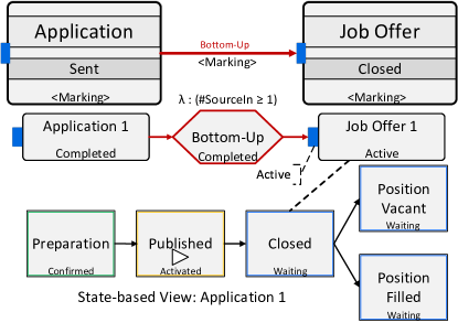
What has been described in Section 6.2 can be considered the linear execution of a coordination process. The coordination process prescribes the coordination step instances to be activated successively, i.e., from start to end of the coordination process. In practice however, the involved process instances usually do not follow the prescribed path of a coordination process neatly. As previously mentioned, processes are executed concurrently and asynchronously, which, for example, results in a plethora of ways a corresponding semantic relationship may come into fulfillment. Moreover, processes may be created and deleted at any point in time, which potentially has profound impact on a coordination process as well. In a nutshell, coordination processes require the capabilities to correctly and flexibly react to a wide variety of situations. The necessary measures taken to make coordination processes flexible are described in the next sections.
6.3 Process Rules
The change in markings of different entities of a coordination process is governed by the application of process rules. Process rules constitute a specific variant of Event-Condition-Action (ECA) rules tailored to coordination processes. In essence, a process rule, i.e., its evaluation, is triggered upon the change of a marking of an entity (event). The process rule then checks markings of the triggering entity (e.g., a coordination step instance) or other entities (e.g., ports) (condition), and assigns new markings to the triggering entity or other entities (action). If conditions are true and actions are performed, the process rule is said to apply. Formally, a process rule as in Definition 26.
Definition 26 (Process Rule)
A process rule has the form ) where
-
•
is the name of the process rule
-
•
refers to a type, denoted as the context type
-
•
is a set of preconditions
-
•
F is a set of effects
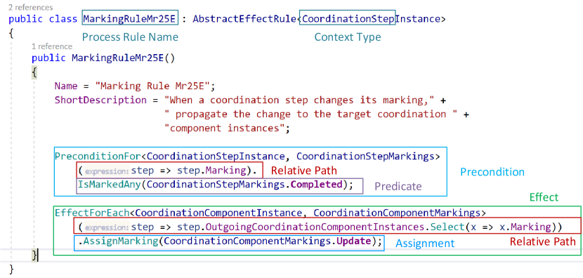
Figure 30 shows a process rule as implemented
in PHILharmonicFlows. Process rules are defined in context of a specific
entity type , called the context type. Only events that are
raised by instances of this specific type may trigger this process
rule. This represents an implicit precondition for triggering this
process rule, always in addition to any further (explicit) preconditions
. An application of a process rule is always evaluated for a specific
instance of type , the context instance . An
example of this behavior is given in Example 27.
Example 27 (Process Rule Context Type)
A process rule has
coordination step type defined as its context type. Consequently,
only an event raised by an instance of this type, i.e., a coordination
step instance, may trigger this process rule. For evaluating whether
process rule A can be applied, the coordination step instance is the
context instance. Consequently, instances of other types, e.g., port
instances and coordination transition instances, need not be checked
for whether process rule may be triggered.
This implicit precondition induced by the context type has two advantages: First, it greatly reduces the search space for possible rule application. Only process rules with one specific context type must be checked for further preconditions , as opposed to all process rules. So applicable process rules may be found faster. Second, the specification of preconditions and effects can be simplified. In addition to the context type, process rules consists of a set of preconditions and a set of effects. Preconditions correspond to the condition of ECA-Rules and effects correspond to the action. Condition and action have been renamed to precondition and effect to avoid ambiguity with other concepts named condition and action in context of coordination processes. Preconditions are defined in Definition 27.
Definition 27 (Precondition)
A precondition has the form where t
-
•
refers to a set of entity instances, relative to context instance
-
•
tests a condition on the entity referred through
The expression returns a boolean value upon evaluation of the precondition and also represents the return value of the precondition as a whole. A process rule is applied when all preconditions of a process rule evaluate to true, i.e., . If all preconditions are true, the process rule is said to match. Simple matching implies that no effects have yet been activated.
The evaluation of the is performed on each entity obtained through . The function maps from the context instance to any set of entities belong to the coordination process graph . are defined in Definition 28.
Definition 28 (Path)
A is a sequence of entities composed with the member access operator (.) or the collection access operators ), starting from a base entity . The collection access operator applies each partial path on the each element of set . A partial path has no base entity defined and can therefore not be fully evaluated unless a base entity is provided. Paths are evaluated from left to right, with the base entity at the left.
allow navigating the coordination process graph and are essential for defining preconditions and effects. Consider again Example 23, where a coordination step instance , marked as , leads to the outgoing coordination step instances becoming marked as . The elicitation of a process rule that accomplishes this is presented in Example 28.
Example 28 (Process Rule Elicitation I)
Upon marking a specific coordination step instance as , it is possible for the associated coordination component instances to become marked as . The context entity type is a coordination step type . The event is a change in the marking of the context instance . The first precondition consists of checking whether the coordination step’s new marking is .
-
•
The is , which navigates from the coordination step instance to its marking. represents the predicate and compares the value of and marking literal for equality. For demonstration purposes and additional safety, it can be checked whether the outgoing coordination component instances are marked as either or . If the outgoing coordination component instances are already marked as , applying the (not yet specified) effects of the process rule is redundant. Furthermore, if, for any reason, the coordination component instances were marked as , it would constitute a violation of the intended semantics of the marking . This violation of the semantics occurs for both coordination step instances and coordination component instances. This would be caught by developers due to the non-application of this process rule and subsequently rectified. The corresponding second precondition is as follows:
-
•
The path contains the collection access operator with the partial path . The operator obtains the marking from each coordination component in , resulting in a collection of markings. Note that this is not a set, as duplicate markings shall be retained. The predicate is then evaluated on each marking in the collection, obtaining a collection of Boolean true or false values. Finally, the collection of Booleans is aggregated into a single Boolean value using AND, representing the result of the precondition.
are defined relative to a base entity for easier specification by a developer and performant evaluation at run-time. Moreover, the simple specification of are the primary driver behind the many mutual references of the definitions of the constituting elements of a coordination process. Simply getting from a coordination step to the next coordination step through the coordination components and their target ports is both performant in the evaluation of the process rule and simple to specify by a developer. This is one contributing factor to Challenge 5 Manageable Complexity.
For efficiency reasons, the preconditions are evaluated sequentially using short-circuit evaluation. That means, if for any reason a precondition evaluates to , process rule evaluation is aborted and the process rule is not applied. This is possible as all preconditions must evaluate to for the process rule to apply.
If all preconditions of process rule are true, i.e., the process rule matches, all effects defined for the process rule are applied. Effects can be specified for any entity reachable by a from the context instance . Effects are defined in Definition 29.
Definition 29 (Effect)
An effect has the form ,
) where
-
•
refers to a set of instances, relative to context instance
-
•
assigns a value to the entity referred through
The of an effect usually consists of assigning a specific marking to an entity. There are, however, other assignments that are used rarely. These rare assignments are omitted here for the sake of brevity. Analogous to preconditions, the entity or entities to which the assignment is made is determined by a . Example 29 continues the process rule elicitation by defining effects (cf. Example 28).
Example 29 (Process Rule Elicitation II)
Continuing the process rule specification of Example 28, the process rule shall mark outgoing coordination components as when a coordination step instance becomes marked as . So far, the context instance and preconditions have been defined:
-
•
Context type is a coordination step type .
-
•
Preconditions are
-
–
-
–
-
–
When both preconditions are true for a given context instance , the following effect is defined:
-
•
Effects are
-
–
-
–
The effect assigns marking to all outgoing coordination component instances in . The path obtains the marking for each outgoing coordination component instance. The expression represents the assignment, with as the assignment operator and as a marking literal.
6.4 Events and Snapshots
The evaluation of process rules is initiated by events. Events are either external or internal in respect to a coordination process instance . An external event is a state change of a coordinated process instance or the creation of a new relation between a process instance and the coordinating process instance of the coordination process. Internal events mostly cover events raised by the change of a marking. Formally, an event is described in Definition 30.
Definition 30 (Event)
An event has the form where
-
•
is the type of the event
-
•
is the origin of the event,
-
•
is the entity that raised
The set of all events is
The type includes types for signifying marking changes, state changes, or relation creations. State changes and relation creations are the main external events that influence a coordination process instance. For the sake of brevity, the full list of event types is omitted here. The origin denotes whether the event is external () or internal (). Some event types may either be external or internal. Lastly, the entity that raised the event is retained. This ties into the context type and context instance of the process rules, as it can be easily determined whether a specific process rule needs to be evaluated for this event.
In order to capture the interplay of coordination process instances, events, and process rules, the concept of snapshot is needed. A snapshot of a coordination process instance captures all entities, markings, properties and references between entities at a specific point in the execution of a coordination process instance. Formally, a snapshot is described in Definition 31.
Definition 31 (Snapshot)
A snapshot has the form where
-
•
is a fixed copy of a coordination process instance
-
•
is a logical timestamp
The tuple denotes a snapshot and a set of new events
With process rules, events, and snapshots defined, the interplay between these concepts can be described. The general principle is as follows: The occurrence of an event associated with a snapshot triggers the evaluation of process rules. If a rule matches, it is applied and a new snapshot and possibly new events are created.
Due to the presence of events in snapshots can be distinguished into stable snapshots (denoted ) and unstable snapshots (denoted as ). In an unstable snapshot , the set of events is non-empty and populated with internal events. Unstable snapshot require further process rule applications. In a stable snapshot , the set of event is empty and no more process rules may be applied. The following sequence describes how snapshots, events, and process rules interact to execute a coordination process instance .
-
1.
Execution starts with a stable snapshot of and an empty set of events . Unless a new external event occurs, remains unchanged and no execution takes place
-
2.
A new external event occurs.
-
(a)
A process rule reacts to , takes the type and the snapshot and assigns new markings to corresponding entities.
-
(b)
Assigning new markings creates a new snapshot of the coordination process instance .
-
(c)
The marking changes raise new internal events, which are added to , creating . Due to being non-empty, is unstable, i.e.,
-
(a)
-
3.
The current snapshot () may be unstable. More process rules may be applied
-
(a)
If continue at (4). If , continue at (3b)
-
(b)
An event is removed from . The event triggers a process rule evaluation.
-
(c)
If a process rule matches, this process rule is applied. This assigns new markings to entities of , thus creating a new snapshot . The marking changes also create new internal events with
-
(d)
Continue at (3) with ()= ()
-
(a)
-
4.
A new stable snapshot = () is created as .
The processing moves a coordination process instance from one stable snapshot to the next stable snapshot. In between these stable snapshots, usually many unstable snapshots occur. When events no longer lead to the successful application of process rules and consequently no more internal events are raised, the set of events becomes empty and a new stable snapshot emerges. Figure 31 exemplifies this graphically.
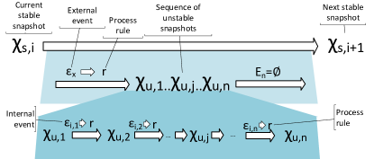
In other words, the sequential assignment of markings leads to a process rule cascade, i.e., the repeated triggering of process rules by other process rules. This cascade passes through a coordination process upon an initial change and assigns new markings in its wake. Sections 6.1 and 6.2 describe one process rule cascade (cf. Figures 25-29). Process rules and process rule cascades drive the enactment of a coordination process.
The cascade stops once a stable state, i.e., snapshot, of the coordination process has been achieved, i.e., no more marking changes are caused by the cascade. Marking change events are considered internal events of the coordination process. Another application of process rules therefore must be triggered from outside the coordination process with a new (external) event. The prevalent external events that affect a coordination process are the state change of a coordinated process or the addition or deletion of a process in the relational process structure that is within the scope of the coordination process. Consequently, changing the state of a coordinated process instance triggers further process rule applications.
6.5 The “Update” Marking
From the exemplary coordination process execution described in Sections 6.1 and 6.2, it may be concluded that markings of, for example, a coordination component, directly influence the marking of its target port. In other words, it is possible to express the dependencies of markings as rules in the form of “If entity X has marking A, entity Y must be marked as B”, where A and B are placeholders for markings and X and Y are entities of the coordination process. For example, when the port of coordination step is marked as , a process rule is triggered which marks the coordination step as as well. This is denoted as determining markings from the outside.
The assumption that applying markings from the outside might work is grounded in the structure of the exemplary coordination process execution itself. One coordination step is connected to exactly one bottom-up coordination component, which, in turn, is connected to one port and one coordination step corresponding to . In short, the coordination process graph is simple and linear. In general however, the structure of the coordination process graph is not always linear. The complex relations of the coordinated processes are mapped to entities of the coordination process, which mirror the same complex relationships. For example, a coordination step may have multiple attached ports (one-to-many relationship), and the ports may have multiple coordination components. The coordination components may be, in addition, of different type. On the other side, coordination steps may have multiple outgoing coordination component. The resulting coordination process graph is not linear, but branched out (cf. Figure 24).
Generally, it is impossible for a port to correctly prescribe the marking of its attached coordination step, i.e, apply a marking from the outside. In order for the port to prescribe the correct marking for the coordination step, the port requires at least knowledge of all its sibling ports and their markings that are attached to the particular coordination step. A sibling port is a port that is attached to the same coordination step. Only by knowing at least the markings of the sibling ports, a port is able to determine the correct marking for the coordination step.
However, the marking of a coordination step is not only determined by its ports. For dealing with more complex and advanced scenarios (some are described in Section 6.6), the port may require information from potentially all the surrounding entities of the attached coordination step. In other words, the marking of a coordination step may be influenced by the markings of the following entities:
-
1.
the attached ports
-
2.
the incoming coordination components belonging to the attached ports
-
3.
the coordination step container
-
4.
the port instance containers belonging to the coordination step container
-
5.
the incoming coordination transitions belonging to the port instance containers
-
6.
the coordination process
-
7.
the state of the corresponding process instance
-
8.
the outgoing coordination components
-
9.
the outgoing coordination transitions belonging to the coordination step container
For the other entities of a coordination process (cf. Definitions 14-24), a similar list of influencing entities exists. This influence is not simply restricted to a coordination step instance. In Figure 32, it is exemplarily shown for port which of the neighboring entities may be relevant for determining the current marking of the step instance. First, the marking of port is changed and the port must set the new marking of the attached coordination step. Consequently, port gathers the necessary information from the neighboring entities of the coordination step, i.e., port looks at their markings (cf. arrows labeled “1” in Figure 32). From the gathered information, the resulting marking of the coordination step is determined and assigned directly to the coordination step by port (cf. arrow labeled “2” in Figure 32). Once the marking of the coordination step changes, the same procedure is triggered on the coordination step, assigning markings to, for example, outgoing coordination components.
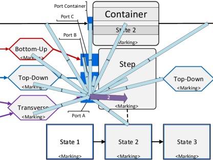
Moreover, a marking change of an entity, e.g., port in Figure 32, may affect the markings of multiple other entities. In case the port determines the new marking of each of the affected entities, the assignment of markings is highly inefficient, as the port may become a bottleneck. Because of the design of markings and process rules, the marking of a particular entity is fully determined by the markings of its neighboring entities. This applies to any entity of a coordination process, creating a mutual interplay between entities due to changes of their markings.
As the marking of an entity is fully described by the markings of its neighboring entities, there is a better possibility to assign markings: This is designated as marking assignment from the inside, as opposed to the previous marking assignment from the outside. Here, the assignment of a new marking for an entity is split into two rule applications:
-
1.
When an entity’s marking changes, a notification rule is tasked with notifying neighboring entities of the change. Returning to the example from Figure 32, when the marking of port changes, a notification rule informs the attached coordination step that its marking must be reevaluated due to the marking change of port . This notification consists of marking the coordination step as (cf. Table 2).
-
2.
The marking is temporary and is only used to trigger an update rule that overwrites the marking with the new correct marking for the coordination step. The update rules take over the task to gather the information from the neighboring entities for assigning the correct marking to the coordination step.
Essentially, the coordination step assigns its own marking via an update rule, hence it is called marking assignment from the inside. Once the correct marking for the coordination step has been determined, notification rules are triggered by the marking change to inform other entities of the change. Consequently, a rule cascade may be triggered until no more marking changes occur.
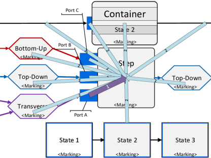
Considering the marking change of port in Figure 32, Figure 33 shows the same situation with marking assignment from the inside. As soon as the marking change of port occurs, a notification rule marks the corresponding coordination step as (see the arrow labeled “1” in Figure 33 ). The coordination step itself now employs update rules to determine its new marking (see the arrows labeled “2” in Figure 33 ).
The division into notification rules and update rules brings notable benefits to coordination processes. In no particular order, the benefits include:
-
•
Process rules become much simpler, as each exactly fulfills one task. Designing the rules that govern process execution becomes easier, and unwanted side effects can be minimized.
-
•
The execution of a coordination process becomes more robust. Overlap between rules or mistakes in process rules that cause interruptions in rule cascades can be easily detected and rectified, resulting in fewer errors.
-
•
Process rules overall become better maintainable. It is immediately traceable which process rule assigned a specific marking, enabling faster debugging in the implementation.
-
•
Feature extensions for coordination processes, which affect the process rules, are easier to implement. Additional process rules can easily be integrated into the existing process rule set; additional markings can be introduced without necessarily breaking existing process rules.
-
•
The notification and update rule model allows realizing a flexible execution of coordination processes more easily. When an update is triggered by setting the marking of an entity to , the resulting marking is determined by the markings of the neighboring entities. With update rules, a specific rule can be specified for any contingency, i.e., any combination of markings in the neighboring entities.
The capability of entities in a coordination process to react to any contingency is one of the greatest strengths of the concept. The coordination of multiple processes running concurrently requires a high degree of flexibility on part of the coordination process. The basic flexibility is delivered by markings, process rules and the overall operational semantics. Section 6.6 gives a rough overview over advanced flexibility requirements in regard to coordination processes.
6.6 Flexibility
The coordination of a myriad of concurrently running process instances is not straightforward and linear. Over the course of their execution, several situations may arise that affect their coordination in profound and non-standard ways. Careful analysis of these situations permitted to incorporate concepts and adaptations into coordination processes. These adaptations allow coordination processes to deal with these situations in a flexible manner. The following unsorted list briefly describes advanced features of coordination processes for which flexibility is paramount. Note that, for the sake of brevity, this list is not intended as a full account of all advanced flexibility features comprised in a coordination process.
Coordination Process Graph Alterations
In classical processes (e.g., a BPMN process), the process graph of a process instance remains largely unaltered during its execution. By contrast, a coordination process graph is designed to change due to the addition of new coordination steps, ports, or coordination components. When adding a new entity to the process graph, the existing entities may have to change their markings accordingly. This is taken into account by the process rules governing the execution of a coordination process.
Arrangement Linking
In this paper, it has been assumed that only a single process instance with no pre-existing relations may be added to a relational process structure at a point in time. However, it may occur that a process instance that becomes linked to a process structure already has pre-existing relations. This is denoted as an arrangement, i.e., a specific configuration of process instances and relations (cf. Section 4).
Example 30 (Arrangement Linking)
An has been reviewed, i.e., it is related to several completed processes, but the show that another than the current one is a better fit for the applicant. Therefore, the arrangement of the and its is moved to another by creating a new relation between the and the other . The are now related as well to the due to transitive relations.
The challenge for the coordination process here is that, first, multiple process instances are linked at the same time, and second, that some of these process instances have been already executed to some degree. The operational semantics of a coordination process takes both challenges into account and can handle them correctly. This can work even when the newly linked arrangement violates some of the constraints of the coordination process. In this case, the coordination process assumes that the execution status of the linked processes is legit and adapts accordingly. This might result in seemingly paradoxical situations, e.g., a state might be marked as , but all the ports and coordination steps associated with the state are marked as . However, coordination processes still handle these situations correctly, e.g., preventing deadlocks. Arrangement linking is a unique feature of coordination processes and relational processes and not found in other approaches.
Dead Path Elimination
When a coordination constraint, i.e., a coordination component, can no longer be fulfilled, the coordination component is marked as . Consequently, successor coordination components and coordination steps, in general, cannot be marked as anymore and must be marked as as well. Therefore, starting from the eliminated coordination component, the coordination process performs a dead path elimination. A process rule cascade is triggered, marking entities as where it can be ensured that they are not able to be activated in the future. For entities for which it is still possible that they can be marked as , e.g., a coordination step having several ports, the dead path elimination stops.
Reverse Dead Path Elimination
Due to the dynamics of process execution and the emergence and deletion of process instances, the elimination of entities in a coordination process is not entirely final. When circumstances that led to a dead path elimination change, it becomes possible that coordination constraints can be fulfilled again. Obviously, this makes the dead path elimination obsolete. Consequently, the dead path elimination must be reversed by marking the affected entities as instead of . Again, a reverse dead path elimination is realized as a process rule cascade in the coordination process.
Backwards Transitions
Generally, the coordinated processes move forward, i.e., states become successively activated from start to end of the process. Therefore, a coordination process has a natural progression from start to end as well, that is in line with the progression of the coordinated processes. However, it is possible that a coordinated process regresses in its execution state, i.e., a predecessor state to the currently active state is activated at a later point in time.
While state-based views do not allow looping, they allow for backwards transitions, i.e., transitions can go opposite the normal direction for transitions from start to end of a process. Backwards transitions allow activating a previous state. In practice, this is very relevant, as oftentimes mistakes may be made that must be rectified afterwards. Otherwise, the mistake may persist, resulting in an overall faulty process execution. By going back to a previous state with a backwards transition, a user is able to correct a mistake made during the execution of that state.
As active states are directly relevant for the activation of constraints, activating a previous state in a coordinated process creates some challenges for the overall consistency.
Example 31 (Backward transitions)
Suppose an has been accepted, i.e., respective and fulfill a coordination constraint that allows for acceptance. If, for some reason, one of the goes back to a previous state, the coordination
constraint is no longer fulfilled. Thus, it can be argued that the acceptance of the is no longer valid.
The simplest solution is to forbid backwards transitions. However, this is unrealistic in practice. Therefore coordination processes do not implement this rigid enactment strategy.
Another possible solution to this issue would be to force the to go back to a previous state as well. This would enable the overall consistency of the coordination constraints in the coordination process, as the is no longer accepted. However, forcing coordinated processes to go back to previous states may have enormous detrimental implications. Depending on which coordinated process goes back to which previous state, potentially a large number of coordination constraints may become invalidated. In turn, this may force a large number of other coordinated processes to regress as well to keep a consistent state. In consequence, the progress of a significant number of process instances might be lost. Additional information loss might incur, depending on how the regress to a previous state is handled beneath the state-based view of the process instances. In principle, the lost progress can be regained afterwards by re-doing the necessary work.
Due to the possibly large ramifications, coordination processes handle backwards transitions differently. As the coordination constraint that allowed the to be accepted was true at one point in time, a regress of a or will not force the to regress as well (cf. Figure 12, coordination constraints \raisebox{-.9pt} {4}⃝ and \raisebox{-.9pt} {6}⃝). Instead, the keeps its current status, but the coordination constraint becomes invalidated. In consequence, eventual future attempts to accept the same again, after the regressed to a previous state, would fail due to the unfulfilled constraint. Note that an may still be manually transitioned into a previous state if desired. Overall, this solution is perceived to be favorable as it allows for backwards transitions.
In general, it may occur during the execution of a coordination process that a state of a coordinated lifecycle process is marked as , yet the coordination steps for the state are or . According to the coordination constraints, the state should not be marked as , which is an inconsistency between coordination process and the coordinated process. Example 31 describes only one situation where such an inconsistency might arise.
In general regarding any inconsistencies, coordination processes take the status of the coordinated process as truth in regard to resolving inconsistencies, i.e., the marking for a state of the process is valid. This is based on the fact that in order for the state to be currently marked as , the activation must have been allowed by a coordination process at one point during the past execution of the particular process. Consequently, subsequent changes in regard to the fulfillment of coordination constraints after the activation of the state have no impact on the state being activated. However, if the coordinated process is executed further, activations of successor states are of course subject to their respective coordination constraints and may only activate if the coordination constraints permit the activation.
Example 32 (Coordination Inconsistencies)
Suppose an is in state for which coordination constraints requires at least three to provide a verdict, i.e, three or more must be in either state or . Currently, the has three in the required states, the coordination constraints currently allow the activation of state , which also has been activated. Now consider the deletion of one , with the effect that the coordination constraint becomes unfulfilled. The remains in state , as the state has been legitimately activated. However, if the attempts to transition to a successor state of (either state or , the coordination constraints prevent activation and instead the state is marked as (cf. Coordination Constraint 5) of Example 10).
The successor state to cannot be activated as there are not enough overall to obtain a conclusive verdict. Note that the involvement of sufficient in the coordination constraints of the successor states is coincidental. In other business processes, the coordination constraints for successor states may be unrelated to the coordination constraints of the current state.
Coordination constraints becoming fulfilled and unfulfilled is one aspect of the dynamics that coordination processes accomplish. The changes over time regarding the coordination constraints create issues regarding the consistency between coordination constraints and coordinated processes. A suitable resolution for these inconsistencies consequently involves the fact that coordination constraints may change over time.For future versions of the coordination process concept, it is conceivable to let a modeler choose the method to resolve inconsistencies, e.g., a modeler may choose that accepted automatically return to a previous state if the coordination constraints for are no longer met.
6.7 Conclusion
In summary, the execution of a coordination process is based on the markings of its various constituting entities. Each marking has a specific significance for the overall business process execution, e.g., particular actions are allowed or disallowed depending on the current markings. The driver behind the execution of a coordination process is a set of process rules that governs how markings change. To provide the required flexibility to deal with numerous different situations, e.g., emergence or deletion of a process instance, process rules are divided into notification rules and update rules.
The way markings and process rules are organized, together with the dynamic process instance representation, conceptually fulfills Challenge 1 Asynchronous Concurrency in the sense that process execution is impacted minimally by a coordination process. In principle, in absence of a coordination process, the execution of any process instance of a relational process structure is fully unrestricted. This means any process may activate states according to its state-based view without interference. If a coordination process exists, the activation of a state may be prevented, but only if several conditions apply.
-
1.
A coordination step must reference the process and a specific state before any coordination constraints may be enforced. Without such a reference, the execution of a process cannot be restricted.
-
2.
At the time the coordinated process wants to activate that state, the coordination constraints imposed by the coordination process must be unfulfilled.
Only if these conditions apply, the activation of a state may be prevented. In all other cases, a coordination process does not affect the execution of the coordinated process. In other words, coordination processes operate according to the blacklist principle: Every action is allowed unless specifically prevented by a coordination process. This allows for a high degree of freedom in executing the process instances while still enforcing all the necessary coordination constraints.
However, for the complete fulfillment of Challenge 1 Asynchronous Concurrency, it must be shown that processes may indeed run concurrently and asynchronously, otherwise the minimal impact of coordination processes would be rendered moot. Section 7 shows that processes may run fully asynchronously and concurrently in the PHILharmonicFlows process management system.
6.7.1 Fulfilling Challenge 5 Manageable Complexity
Regarding Challenge 5 Managing Complexity, the concepts that have been described in Sections 4-6 are hardly noticed by an end user executing the coordinated processes. Effectively, the only effect of these concepts for the end user is whether or not a coordination process allows activating a state, and if not, why it is prevented from activation. Consequently, except for this, a coordination process and its execution may be fully hidden from an end user at run-time. Thereby, the complexity perceived by an end user at run-time is very low, though the complexity of the run-time coordination process is high.
Regarding the complexity for a process modeler at design-time, a detailed understanding of coordination processes, as presented in this paper, is overall beneficial, though not required. A process modeler would need to know the definition and usage of semantic relationships and how multiple process instances are dealt with in a coordination process. Furthermore, the definition and usage of each process modeling element and its properties. This is analogous to BPMN 2.0 (Object Management Group, 2011), where a modeler requires knowledge about the function of each modeling element, for example an inclusive gateway, yet not how this functionality is exactly provided by the BPMN process engine. There are significantly less process modeling elements for coordination processes and object-aware process management that for BPMN. Therefore, the argument can be made that coordination processes possess less or at the very least equal complexity in regard to modeling as BPMN 2.0 while simultaneously fulfilling all challenges. This fulfills Challenge 5 Manageable Complexity from the viewpoint of the process modeler.
For developers, the PHILharmonicFlows process engine (cf. Section 7) is the proof that implementation of all concepts and challenges is feasible. The PHILharmonicFlows process engine fully supports all challenges as stated in this article and all requirements imposed by object-aware process management. Therefore. the complexity of implementing coordination processes and its related concepts is manageable, fully supporting Challenge 5 Manageable Complexity from the viewpoint of the developer.
In general, for both run-time and design-time , the complexity perceived by end users, process modelers, and developers is significantly lower than the actual complexity of the concept. As such, Challenge 5 Managing Complexity can be regarded as accomplished.
7 Technical Implementation and Evaluation
Coordination processes originate in the object-aware process management paradigm (Künzle and Reichert, 2011). The concepts of object-aware process management, i.e., objects, lifecycle processes, relations, and coordination processes, have been implemented in the PHILharmonicFlows prototype. It has been shown that coordination processes impact process execution as minimally as possible, as demanded by Challenge 1 Asynchronous Concurrency. In order to completely fulfill Challenge 1, it remains to show that PHILharmonicFlows is indeed capable of executing processes fully asynchronously and concurrently, which is achieved with actors and microservices (cf. Section 7.1). Otherwise, coordination processes would not fulfill Challenge 1 Asynchronous Concurrency to full extent. Finally, Challenge 4 Immediate Consistency is discussed in Section 7.2.
The challenges and operational semantics stand in the context of the re-implementation of the prototype of PHILharmonicFlows. The initial prototypical implementation of PHILharmonicFlows as an object-aware process management system was developed from 2008 to 2012. It involved functional design- and run-time of the basic concepts of object-ware process management, though many advanced features could not be realized due to the technology available at the time. These imposed severe limitations on the functional and technical capabilities of the prototype.
In 2015, a fully new implementation internally named “Proteus” was started, leveraging the emerging concepts of microservices (Andrews et al, 2018). Microservices allow for a scalable and performant execution of object-aware processes, resolving many of the previous limitations. However, this also rendered almost all of the existing codebase of the previous prototype obsolete. The re-implementation of PHILharmonicFlows also paved the way for the development of advanced features such as ad-hoc changes for object aware-process management (Andrews et al, 2019) and a hyper-scalable run-time environment (Andrews et al, 2018). This new and improved microservice-based implementation continues using the branding PHILharmonicFlows. The new paradigm of microservices also required to re-think and adapt many concepts of object-aware process management, accounting for the new requirements imposed by this fundamental change of using microservices. Concepts such as object lifecycles , the relational process structure, and coordination processes were extended and also adapted, with a major focus on the run-time (Steinau et al, 2017, 2018a, 2018b). These extensions and adaptation both represent evolutionary and revolutionary changes. In particular, the operational semantics of coordination processes required a substantial overhaul and, therefore, pose a novel contribution. This overhaul of the operational semantics simultaneously drove and was driven by the re-implementation of the PHILharmonicFlows system, constituting a high practicality.
7.1 Actors and Microservices
With PHILharmonicFlows, much effort has been put into development to create a scalable process management system that supports many concurrently running processes (Andrews et al, 2018). The paradigm of object-aware process management is uniquely suited for this, as its conceptual elements, e.g., objects and their lifecycle processes, can be represented with actor theory as individual actors (Agha and Hewitt, 1988; Hewitt, 2010). PHILharmonicFlows uses a variant of actors with reliable messaging. In essence, an actor is an independent entity that consists of a message queue and a store for arbitrary data. An actor may receive messages from other actors or from external sources, and process them using data contained in the message and data from its store.
An actor may only work on exactly one task at a time, i.e., it runs conceptually on one single computational thread. An actor servicing a message may only work on that one message, all other messages are put in the queue until the current message has been serviced. Messages are not fire-and-forget, but have callbacks. An actor system is realized by having multiple actors of different types that express different functionality. In this system, actors then may run concurrently and in parallel. Due to using a single computational thread and message queuing, most of the concurrency problems regarding persistence and computation, e.g., race conditions and dirty reads/writes, are not present in an actor system. Moreover, actors may communicate asynchronously.
PHILharmonicFlows is realized as such an actor system. Each object instance, together with its lifecycle process instance and its attributes, is implemented as one actor. A lifecycle process of an object conforms to the definition of process type (cf. Definition 1). Coordination processes are actors as well, but of different actor type. Figure 34 shows a schematic view of actors and their communication. In particular, an actor may involve other actors when servicing a request, as required data or functionality may be located in other actors. Note that in Figure 34, Actor A is servicing an external request, depicted by the message in its message queue and the outgoing communication from its thread.
Each actor in the PHILharmonicFlows system is realized as a microservice using Microsoft’s Azure Service Fabric Framework111https://docs.microsoft.com/en-us/azure/service-fabric/. Azure Service Fabric combines microservices with the actor paradigm, and is therefore an ideal technical framework for building PHILharmonicFlows. The overall architecture of the PHILharmonicFlows system can be seen in Figure 35. As shown in (Andrews et al, 2018), PHILharmonicFlows scales very well horizontally, i.e., across distributed machines or a cloud.
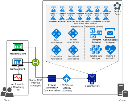
Microservices may run concurrently or in parallel by definition. As each process is implemented as a microservice, logically the concurrent execution of process instances is therefore guaranteed.
Still, the implementation must also enable the asynchronous interactions between processes. Any object lifecycle process is, in principle, independent from any other object lifecycle process, i.e., there is no synchronization between any kind of processes. The only exception is the coordination process. Conceptually, semantic relationships enable the asynchronous execution of the processes. Semantic relationships are represented by actor data and several communication patterns between actors to represent their functionality at a fundamental level. Their implementation uses the message stores and message exchange capability of the actors. Therefore, semantic relationships are abstractions over multiple, conditional series of messages between actors. As actors are inherently capable of asynchronous communication, the implementation of semantic relationships enables asynchronous process interactions as well. Therefore, true asynchronous execution of interdependent lifecycle processes is enabled by PHILharmonicFlows.
In summary, PHILharmonicFlows is capable of executing a multitude of processes concurrently and in parallel due to the use of the Azure Service Fabric Framework to implement the concepts. Asynchronous communication is enabled by the underlying actors. Therefore, Challenge 1 Asynchronous Concurrency is fully supported by coordination processes as implemented in PHILharmonicFlows.
7.2 Coordination Process Performance
The challenge that has not been discussed so far is Challenge 4 Immediate Consistency. It is essentially concerned with the performance and partly with the correctness of a coordination approach. For coordination processes, it has been shown in Sections 5 and 6 how the coordination process is kept up to date on a qualitative level. For the purpose of this paper it is assumed that coordination processes work correctly, i.e., they are updated correctly as required and they send correct updates to the coordinated processes (i.e., the lifecycle processes). Therefore, only the actual performance of coordination processes is important in this context.
To prove that coordination processes fulfill Challenge 4 Immediate Consistency, the following experiment was set up. It must be demonstrated that the execution time of the processes in a process structure that is coordinated by a coordination process is not significantly larger than the same process executions without the involvement of a coordination process. In other words, coordination processes do not create a significant overhead.
For the quantitative assessment in form of performance measurements, two different PHILharmonicFlows business process models were defined - the recruitment business process from the running example (cf. Example 1) and an insurance claim business process (cf. Figure 36). Both possess exactly one coordination process, but the insurance claim model is slightly larger. Additionally, a variant of each business process model exists where the coordination process has been entirely removed from the model, i.e., only objects and their lifecycle processes remain. This means that no coordination constraints can be enforced at run-time.
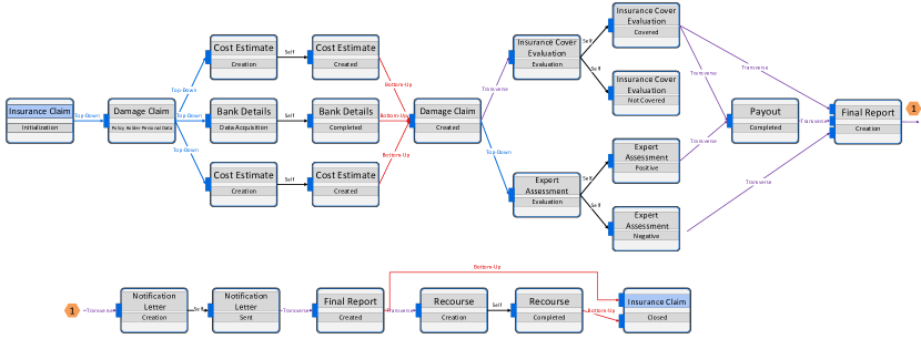
| Function | Description |
|---|---|
| Creates a new instance of process type | |
| Creates a new relation instance between process instances and . | |
| Writes value of an attribute instance that has type of process | |
| Commits transition that has type of process . Implies a state change of |
Furthermore, for each business process model, an execution sequence was defined that resembles a fairly standard and sufficiently complex execution of the business processes. An execution sequence defines a series of actions, describing at which points process instances are created or deleted, or when they change state. In detail, an execution sequence action is created using one of the following functions (cf. Table 6) and supplying it with concrete parameter values.
Function creates a new process instance, given a corresponding process type . Function takes two process instances and as arguments and creates a relation between them, provided a corresponding relation type was specified at design-time. Moreover, function writes value to the attribute instance of process instance . Attribute instances are part of an object instance in PHILharmonicFlows and can be uniquely identified by its type , which occurs only once in each object instance . In case already has a value, the value is overwritten with . Finally, function causes a state change, i.e., after committing the transition, the active state is the target of the transition.
It is possible to execute processes using only these four main functions (cf. Table 6). This is due to the underlying data-driven lifecycle processes in PHILharmonicFlows, which the business process models are based on. Lifecycle processes are enacted by acquiring data values for attribute instances . The details of lifecycle process execution have been shown in (Steinau et al, 2019). Based on the four functions, an execution sequence is designed that realizes a full business process execution involving multiple process instances which are being coordinated by a coordination process.
The execution sequence describes how instances of both business process model variants are executed, i.e., any instance of the business process model with and without the coordination process performs the same actions in the same order. The execution sequence is designed to not violate any coordination constraints, in order to achieve identical results even when there is no coordination process involved. Otherwise, in one case, an action may be blocked by a coordination process, whereas in case of a missing coordination process, the action would be allowed, creating different results and therefore bias in the performance measurements. A full description of both business process models with high-resolution graphs, together with the detailed execution sequences and their descriptions, has been made available222The data can be found at https://bit.ly/2DvFZvk.
As PHILharmonicFlows supports parallel and concurrent (lifecycle) process execution as enabled by the actor microservices, performance measurements follow the guidelines for measuring the performance of parallel computing systems, as defined in (Andrews et al, 2018). Here, the experiment reuses the exact methodology from (Andrews et al, 2018) and is therefore not replicated in detail here for the sake of brevity. The general idea is to dynamically determine the number of runs needed to achieve a given confidence interval for the value that is measured.
| # | Model | Instances | Actions | Confidence | Confidence | ||||
|---|---|---|---|---|---|---|---|---|---|
| 1 | Recruitment | 96 | 289 | [00:01:769, 00:01:882] | 6 | 96.88 | [00:03:619, 00:03:720] | 6 | 96.88 |
| 2 | Recruitment | 32 | 82 | [00:00:502, 00:00:530] | 6 | 96.88 | [00:00:911, 00:00:978] | 6 | 96.88 |
| 3 | Insurance | 18 | 168 | [00:01:069 - 00:01:140] | 6 | 96.88 | [00:01:420, 00:01:478] | 6 | 96.88 |
The measured value is the execution time of the execution sequence with coordination by by a coordination process. For comparison, denotes the time for enacting the execution sequence without a coordination process. and are the summation of the execution time of each individual action in the execution sequence.
As stated in Section 2, immediate consistency is achieved if users do not experience delay when issuing two consecutive actions. The book “Usability Engineering” (Nielsen, 1993) contains three tiers for response times of software systems with respect to the user experience, stated as follows:
-
•
0.1 second is about the limit for having the user feel that the system is reacting instantaneously, meaning that no special feedback is necessary except to display the result.
-
•
1.0 second is about the limit for the user’s flow of thought to stay uninterrupted, even though the user will notice the delay. Normally, no special feedback is necessary during delays of more than 0.1 but less than 1.0 second, but the user does lose the feeling of operating directly on the data.
-
•
10 seconds is about the limit for keeping the user’s attention focused on the dialogue. For longer delays, users will want to perform other tasks while waiting for the computer to finish, so they should be given feedback indicating when the computer expects to be done. Feedback during the delay is especially important if the response time is likely to be highly variable, since users will then not know what to expect.
Ideally, for optimally fulfilling Challenge 4 Immediate Consistency, each action in the execution sequences should require less than 0.1 second for execution. Formally, several goals are defined for Challenge 4 Immediate Consistency. The primary goal is stated as follows:
Goal 1 (Primary)
Each action in the execution sequence should remain below 100ms of execution time
If this goal is unattainable, a secondary goal is defined:
Goal 2 (Secondary)
Each action in the execution sequence should remain below 1000 ms of execution time
The overall execution times of both business processes “Recruitment” and “Insurance” are less important regarding Challenge 4 Immediate Consistency. Nevertheless, they are reported in Table 7 as they give an overall impression of the performance of the PHILharmonicFlows process engine. All execution times are given as standard intervals of the format , where time has the format . Three scenarios #1-3 were run, two times using the recruitment business process (i.e, the running example), and one time the insurance business process, with the coordination process shown in Figure 36. Scenario #1 is the recruitment business process, where 5 are submitted and reviewed, each having 3-5 . Scenario #2 is a cut-down version of Scenario #1, where only one is submitted and subsequently accepted to fill the position. Scenario #3 is an insurance business process, comprising one instance of each of the eighteen process types.
As can be seen in Table 7, running the same execution sequence with a coordination process takes roughly twice the time compared to running it without any coordination process. However, given the number of process instances (96) and actions (289) in Scenario #1, total execution time manages to remain below the 4 second mark. Scenarios #2 and #3 have less actions and, consequently, achieve better total execution times. Note that the execution sequences produce very consistent results, as it takes only the minimum number of runs (6) to obtain the necessary confidence level of %.
The execution sequences have been designed to resemble what can be considered fairly standard process executions. Still, the sequences try to prolong process execution. Whenever branches may be chosen during decisions, the execution sequence chooses the longer path. Furthermore, the execution sequences take no advantage of executing processes concurrently, as in principle enabled by PHILharmonicFlows engine. Each sequence simulates a single user, executing each action of the execution sequence strictly sequentially. Note that this does not prevent the PHILharmonicFlows engine from using any parallelism, as it has been designed for high parallelism regardless of how an execution sequence is structured. Still, the execution sequences constitute a worst case as far as the concurrent execution of processes is concerned.
| Total Time | Average | Median | Minimum | Maximum | ||||||
|---|---|---|---|---|---|---|---|---|---|---|
| No CP | CP | No CP | CP | No CP | CP | No CP | CP | No CP | CP | |
| 00:378 | 00:393 | 00:012 | 00:012 | 00:011 | 00:011 | 00:010 | 00:010 | 00:021 | 00:025 | |
| 00:344 | 00:411 | 00:003 | 00:003 | 00:002 | 00:003 | 00:001 | 00:001 | 00:009 | 00:010 | |
| 00:223 | 01:291 | 00:003 | 00:017 | 00:003 | 00:011 | 00:002 | 00:002 | 00:007 | 00:047 | |
| 00:738 | 01:529 | 00:024 | 00:049 | 00:023 | 00:048 | 00:021 | 00:023 | 00:030 | 00:083 | |
Moreover, the business process models used for the measurements require a high amount of coordination. Especially, the recruitment example shows very tight coordination. The business process model comprises 4 processes with 5 states each, and of these 20 states in total, 4 are not subject to coordination by a coordination process (cf. Figures 7 and 12). As such, the business process model nearly maximizes the amount of coordination, leading to almost another worst case for the total execution time. The insurance scenario is less tightly coordinated. In light of these detrimental conditions, a maximum execution time of less than 4 seconds for scenario #1 is satisfactory.
All performance measurements have been run on a Lenovo T470p notebook. The notebook features an Intel(R) Core(TM) i7-7700HQ 4 Core/8 Thread CPU running at base clock 2.80GHz in stock configuration. The CPU was neither overclocked, nor undervolted nor locked to a specific frequency. The notebook has 16 GB RAM DDR3-2400 and an SSD. Software-wise, it runs Windows 10 Pro x64 v1903 and Visual Studio Enterprise in the most up-to-date version (v16.0.9, as of October 15th, 2019), and the debug-compiled, up-to-date PHILharmonicFlows software. The performance measurements were performed with the notebook plugged in, using best performance mode of Windows 10.
For Challenge 4 Immediate Consistency, the performance measurements captured the execution time of each action during the last run of Scenario #1. Figure 37 shows a chart of Scenario #1, comparing the execution times with a coordination process to the execution times without using a coordination process.
Figure 37 shows that coordination processes only delay some actions. The actions derived from function experience significantly higher execution times if coordinated by coordination processes. Moreover, actions that use require additional execution time because of the coordination processes, though not as much time as with function . Actions derived from function and function do not experience higher execution times.

Regarding the execution times of each individual action, it can be noticed that coordination processes do have a significant impact, sometimes doubling or tripling the required execution time of a particular action (cf. Figure 37). However, the maximum execution time of any action in the execution sequence is 83 ms involving a coordination process. In consequence, the primary goal has been completely achieved (cf. Goal 1), i.e., each action does not go over 100ms of execution time even with a coordination process involved.
Table 8 summarizes metric scores related to the performance measurements. As these are based on a single run, there is no variance and the interval notation of Table 7 is not needed. The data is obtained from the last (i.e., sixth) run of Scenario #1 with and without a coordination process, as the total execution time is guaranteed to be within bounds and therefore representative.
Again, the time for a run of with a coordination process is noted as 83 ms at maximum, confirming the chart in Figure 37. Table 8 also reveals that the coordination process predominantly affects execution times of functions and . Moreover, it can be observed from the averages and the median that the total execution time is comprised of many actions with very low execution times and a few other actions with very high execution times.
Consequently, a favorable user experience is ensured.
In summary, it has been shown that each action in several execution sequences remains below 100ms of execution time, fulfilling the primary Goal 1. This is valid for several different scenarios involving different models and instance counts. In conclusion, Challenge 4 Immediate Consistency may be regarded as fulfilled, as there are scenarios which meet the requirements. With the fulfillment of the remaining Challenge 4, all five Challenges are fulfilled simultaneously by object-aware process management and PHILharmonicFlows.
7.3 Execution of an Object-aware Business Process
In order to showcase that coordination processes and their implementation are working, a screencast333https://vimeo.com/389004670 has been created. It shows the execution of the recruitment business process introduced in Example 1. The recruitment process starts with the creation of a process and its publication. Several are created and subsequently reviewed. Throughout the screencast, it is checked whether the coordination process enforces the coordination constraints (cf. Example 1). For one , an is created, and in the following the is accepted. Other then must be rejected. The screencast concludes with the reaching the end state. Figure 38 shows a screenshot of the Runtime Tool depicting the same process as in the screencast.
The intention of the screencast is to demonstrate the complexity of the coordination of interdependent business processes and to emphasize that the presented challenges occur in practice. Furthermore, it is intended to show that the concepts presented in this paper manage to properly coordinate interdependent processes, creating a purposeful overall business process. The screencast shows that the presented concepts are already implemented in working software.
7.4 Case Study: E-learning Platform
PHILharmonicFlows is applied to a sophisticated real world scenario involving an e-learning platform. PHILharmonicFlows is used to realize an e-learning platform called Phoodle, which supplants the regular Moodle e-learning platform in a lecture. Phoodle was used throughout the whole semester to support the lecture. More specifically, Phoodle implemented the following basic functionality. The highlighted words are relevant objects with lifecycles.
-
1.
Creation of lectures and associated elements, such as exercises.
-
2.
Supplementary material to the lectures, such as slides or videos, are available as a download from the platform.
-
3.
Students should be allowed to register for and attend lectures and participate in exercises
-
4.
Supervisors create exercises and publish these on a weekly basis
-
5.
Students create solution submissions for these exercises.
-
6.
Tutors grade the submissions from the students and give feedback.
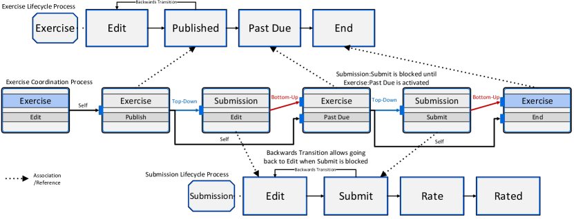
The primary intention with Phoodle was to research how well the complexity of an object-aware business process can be concealed from end users. Furthermore, it was of interest which issues arise when using completely generic business process management software to implement real-world software. The Phoodle e-learning platform is realized entirely as a PHILharmonicFlows business process. More specifically, one instance of the Phoodle business process was used. The web-based front-end is completely generic as well, except for a configuration option for connecting to the Phoodle business process instance on the PHILharmonicFlows server.
Figure 40 shows the relational process type structure for Phoodle. The roles of student, supervisor and tutor are realized via the relations between the user type and other object types (Andrews et al, 2017), e.g., a person obtains the student role by creating an for a . Tutor and Supervisor roles are coupled to the and object types, respectively.
Coordination processes are used to control the interactions and . Figure 39 shows the lifecycle processes for and as well as the coordination process. Once an has been created and published by a supervisor, students are allowed to create and edit . Students must submit their solution before a predefined deadline, but are permitted to alter and re-submit their submission. Altering the submission is achieved with a backwards transition from state to of the object.
State is designed to contain no activities, as it is only used to indicate the status of the lifecycle and requires no further functionality. However, this creates the following issue in the process: Without a coordination process, once state is activated, the lifecycle process immediately activates state , where a Tutor is supposed to grade the submission. This is unintended behavior, as the student can no longer correct mistakes in his submission, as there is no backwards transition from to .
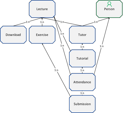
In this case, the coordination process is used to correct this unintended behavior. With the coordination process as shown in Figure 39, a coordination constraint is introduced that prevents from activating. In consequence, when the student triggers the transition from to , is marked as (cf. Table 3). States marked as permit activating backward transitions, so the student may alter the submission. However, the may only go into state when the deadline for to the has been reached and the is in state . As the state contains no activities, state is activated immediately upon the reaching state . This is the fully realized and intended behavior by Phoodle, which cannot be achieved without a coordination process.
During the semester, the instance of the Phoodle business process registered 136 distinct users (students, supervisors and tutors) and logged over 40,000 interactions from these users. In total, the instance comprised 2898 microservices representing 848 object instances, 1542 instances of relations between these objects, 5 coordination process instances, and 503 uploaded files.
In summary, process coordination is indispensable for the correct functioning of the Phoodle business process. The Phoodle business process furthermore showed the importance of considering complex relationships between processes. Finally, the case study demonstrated the viability of PHILharmonicFlows and object-aware business process management in practice.
8 Related Work
The topic of coordinating interdependent processes is connected to many different subjects. Primarily, data-centric approaches or other approaches relying on multiple interdependent processes, summarized in short as interaction-centric approaches, are closely related work. Activity-centric processes and choreographies are also relevant due to their prevalence in both the BPM field and the industry. Overall, as this paper is concerned with process coordination and its enactment, preference is given to related work that describes interactions between processes, covering the execution phase of the BPM lifecycle (Dumas et al, 2013). Further emphasis is placed on the approach having (formal) operational semantics.
8.1 Interaction-centric Approaches
Interaction-centric approaches are predominantly defined by the interactions between different processes.
Proclets are small, lightweight processes that focus on interactions between processes (van der Aalst et al, 2000, 2001). The proclet approach was one of the first to abandon monolithic process models in favor of small, interacting processes. Proclets are defined using the well-known formalism of Petri nets, recognizing that instances of proclets may need to communicate with more than one other proclet. Therefore, the proclet approach supports one-to-many interactions between proclets. For this purpose, the Petri net formalism is extended with ports, enabling communication to other proclets. Ports are fully integrated into the Petri net formalism, supporting the usual formal analysis techniques known from standard Petri nets. Using ports, channels connect to ports on other proclets, over which performatives may be exchanged.
The actual communication between proclets over a channel is realized by performatives, a special form of message. One of the major advantages of the proclet approach is the support for the full range of formal analysis techniques enabled by Petri nets. However, Petri nets can only describe imperative processes, thus they are limited in their support of flexible enactment of the processes.
Artifact-centric process management (Nigam and Caswell, 2003) describes business processes as interacting artifacts with lifecycles. Central to this approach is the artifact, which holds all process-relevant information in an information model. The artifact lifecycle is specified using the Guard-Stage-Milestone (GSM) meta-model (Hull et al, 2011b, a). An artifact may further interact with other artifacts. However, GSM does not provide dedicated coordination mechanisms or explicit artifact relations, as does object-aware process management. Instead, GSM incorporates an arbitrary information model and an expression framework with which artifact interactions may be specified. While this, in theory, allows expressing any concept or constraint, in practice much of the capabilities of artifact-centric process management hinge on the power of the expression framework. As a drawback, expressions might become very complex and must be supported by a rule engine to realize the full potential of artifact-centric process management. The concepts of the relational process structure and the semantic relationships may be recreated with complicated expressions to achieve at least the basic functionality of coordination processes. While this is not impossible, it requires great effort on the side of the modeler to achieve the same functionality as object-aware process management provides out-of-the-box. Consequently, the fulfillment of the challenges is possible in principle, but depends highly on the used expression framework and the way the specific artifacts and business processes are modeled.
Artifact-centric process management has been prototypically implemented in the BizArtifact demo tool444https://sourceforge.net/projects/bizartifact/, whose predecessors include Barcelona (Heath et al, 2013) and Siena (Cohn et al, 2008). Due to the complexity of an artifact-centric business process, model verification (Belardinelli et al, 2012; Bagheri Hariri et al, 2013) constitutes an important aspect of artifact-centric process management. Moreover, several variants of artifact-centric process management exist. For artifact-centric process management and the modeling language GSM, (Damaggio et al, 2013) have proved that incremental and fixpoint semantics for GSM models are equivalent in their expressiveness. This is an important stepping stone towards the full verification of GSM-based artifact-centric process models. (Bagheri Hariri et al, 2013; Calvanese et al, 2012) investigate artifact-centric processes in regard to evolving databases with the intent to verify process correctness, leading to the creation of data-centric dynamic systems (Russo et al, 2013, 2014; Montali et al, 2014).
Artifact-centric hubs are one of the first ideas to allow for collaboration using artifacts (Hull et al, 2009). However, the interactions take place between process participants, not among the artifacts themselves. Participants use artifacts to interact with one another, where an artifact is similar to a bulletin board. (Lohmann and Wolf, 2010a) reused basic ideas that led to the creation of artifact-centric hubs, but instead used these ideas for introducing an approach for artifact choreographies. Process participants, called agents, use artifacts and execute them, and artifacts have a specific location. By knowing where artifacts are located and who is using them, a choreography between these agents can be automatically generated. While both (Hull et al, 2009) and (Lohmann and Wolf, 2010a) have created approaches for managing interactions, the interacting parties are not the artifacts themselves. Instead, choreographies between participants are created, constituting a stepping stone towards artifact-based interorganizational business processes. Therefore, both approaches are not directly comparable to coordination processes.
By contrast, (Sun et al, 2012) created an approach for providing declarative choreographies for artifact-centric processes where artifacts actually interact. The artifacts in this approach use a type-instance schema as well. Declarative choreographies recognize the need for explicitly knowing the relations between artifacts and their multiplicity. Consequently, one-to-many relationships and many-to-many relationships are supported by a concept called a correlation graph. The artifact instances are coordinated using messages, which are exchanged based on the constraints of the declarative choreography. These constraints are specified using expressions, where the expressions require greater expressiveness than the expressions used for semantic relationships, making expressions for artifacts more complicated in comparison.
In (Fahland et al, 2011), the need for supporting many-to-many relationships when dealing with interactions between artifacts is recognized, i.e., Challenge 2 Complex Process Relations. However, artifact lifecycles are specified by using Petri nets, specifically proclets, instead of GSM, with the intention of using the well-known formal properties of Petri nets to verify an entire artifact-centric business process. This work is expanded in (Fahland, 2019), where many-to-many interactions between processes are fully incorporated into the Petri net descriptions of these processes. The interactions between different Petri net processes are expressed in terms of correlation and cardinality constraints, and full operational semantics is provided. This form of description is accessible for formal reasoning and verification. (Fahland, 2019) aims for notational simplicity by using as few syntactical concepts as possible, i.e., Petri nets only. This stands on the opposing site to coordination processes and object-aware process management, aiming for high-level abstractions for different concepts by using appropriate notations.
The coordination of large process structures with focus on the engineering domain is considered in (Müller et al, 2007, 2008). The COREPRO approach explicitly considers process relations with one-to-many cardinality as well as dynamic changes at run-time, but transitive relations are not considered. In comparison to COREPRO, semantic relationships correspond, in principle, to external state transitions of a Lifecycle Coordination Model. However, the external state transitions do not take the semantics of the respective process interaction into account.
8.2 Activity-centric Approaches and Choreographies
Activity-centric process management approaches mostly produce monolithic models. Consequently, interactions between various processes mostly occur only in an inter-organizational setting, where the business processes of different companies must interact. One of the most popular process modeling languages for activity-centric processes is described in the BPMN 2.0 standard (Object Management Group, 2011). The BPMN 2.0 modeling language expresses process interactions as message exchanges between processes, which are organized sequentially. Moreover, BPMN 2.0 provides choreography diagrams as an abstractions over the fleshed-out process diagrams in standard collaboration diagrams. Regarding interactions, BPMN 2.0 choreographies possess the same capabilities and expressiveness as collaboration diagrams, as both can seamlessly be integrated with each other. Consequently, a discussion of choreography diagrams is sufficient for assessing interactions in BPMN 2.0, a separate discussion of collaboration diagrams is redundant .
BPMN 2.0 processes, as well as their message exchanges, use well-established token semantics (Object Management Group, 2011). Conceptually, one or more tokens move through a BPMN 2.0 process diagram, indicating which activities may be executed next. The flexibility limitations of these semantics have been well established, as demonstrated with declarative activity-centric languages (Pesic and van der Aalst, 2006). Moreover, message exchanges in BPMN 2.0 are required to be synchronous, i.e., both processes must either be in a position to sent or receive a specific message in order for a successful message exchange. Therefore, due to the imperative nature of the BPMN 2.0 choreography diagram and its synchronous message exchanges, there is less flexibility when executing the interacting processes compared to a coordination process.
BPMN 2.0 has become an industry standard and is the predominant modeling language for processes in general, the following discusses each challenge briefly.
-
•
Challenge 1 Asynchronous Concurrency has only limited support from BPMN. Concurrent processes only occur when modeled in pools, which is mainly the case for inter-organizational settings. While these processes may run asynchronously, this property is hampered by the synchronous message exchanges between processes. Subprocesses are executed completely synchonously to their parent process, and the parent process is halted while the subprocesses are running.
-
•
BPMN 2.0 has means to describe one-to-many relationships between processes with multi-instance pools and multi–instance or loop activites. BPMN 2.0 therefore partly fulfills Challenge 2 Complex Process Relations. However, cardinalities for the interacting processes cannot be defined. Moreover, transitive relations and many-to-many relations between processes are not supported. In general, explicit relations between processes are not part of the concept of BPMN. The concept of correlation keys are used to identify groups of message exchanges (“conversations”) and have therefor a very different function as relations. Correlation keys are further incapable of providing the same functionality as relations and are not defined at the model level (Meyer et al, 2015). Moreover, the support of multi-instance pools and activities is lacking in BPMN 2.0 process engines (Geiger et al, 2018), which is required for the complete fulfillment of Challenge 2 Complex Process Relations.
-
•
Challenge 3 Local Contexts cannot be supported in BPMN 2.0 due to missing explicit relations and transitive relations.
-
•
BPMN 2.0 does not state any performance goals for the execution of its processes nor for the engines that execute these processes. Moreover, as BPMN 2.0 modelers do not consider vast structures of interrelated processes (zur Muehlen and Recker, 2013), support for Challenge 4 Immediate Consistency has understandably not been considered. It is also infeasible to realize the requirements of Challenge 4 Immediate Consistency by using BPMN 2.0 data objects associated with activities, as neither of these concepts is remotely suited for implementing consistency (Object Management Group, 2011).
-
•
Regarding Challenge 5 Manageable Complexity, as BPMN 2.0 does not fulfill Challenges 1-4, it must be concluded that BPMN 2.0 does not possess manageable complexity as defined by the challenge. However, BPMN 2.0 has become an industry standard. As such, it is highly unlikely that the complexity of BPMN 2.0 is prohibiting the use of the standard. Otherwise, it would have hardly become an industry standard. Still, process engines tend to struggle with implementing advanced concepts of BPMN 2.0 (Geiger et al, 2018) and only a subset of modeling elements is used in practice (zur Muehlen and Recker, 2013).
iBPMN is an approach to specify process choreographies for BPMN 1.2 processes (Decker and Weske, 2011). While BPMN 1.2 focused on interconnection modeling, iBPMN introduced interaction modeling to process choreographies. This allows avoiding many of the pitfalls of interconnection modeling. The iBPMN approach has defined formal execution semantics based on a Petri net variant called interaction Petri net. As such, iBPMN can leverage much of the analysis techniques of regular Petri nets. iBPMN highly influenced the design of the BPMN 2.0 choreography diagram. Consequently, iBPMN shares much of the same shortcomings of BPMN 2.0 choreography diagrams as well. Namely, Challenges 1-3 are not or only rudimentarily supported.
| Comparison Criteria | Artifact-centric (GSM) | Artifact-centric (Proclet) | Proclets | BPMN | Corepro | Coordination Processes |
|---|---|---|---|---|---|---|
| Asynchronous Concurrency | (✔) | (✔) | ✔ | |||
| Complex Process Relations | (✔) | ✔ | (✔) | (✔) | ✔ | |
| Local Contexts | (✔) | ✔ | ||||
| Immediate Consistency | ? | ? | ? | ? | ✔ | |
| Manageable Complexity | ? | ? | ? | ? | ? | ✔ |
| message-based | ✔ | ✔ | ✔ | ✔ | ||
| paradigm-agnostic | ✔ |
| ✔ : Supported | (✔) : Partially supported | ? : Unknown |
(Meyer et al, 2015, 2013) build upon BPMN 2.0 choreographies to provide automated data exchange between process participants. Several challenges are addressed, among them the data exchange between processes in a simple one-to-many relationship. Neither transitive or many-to-many relationships are considered. The approach elevates several properties to the model level, such as message exchange formats and correlation keys, and utilizes these to automatically derive SQL queries to populate the content of messages at run-time.
As with artifact-centric process management, several articles are concerned with the verification and correctness of choreographies in an activity-centric setting. Specifically, the absence of deadlocks is often topic of investigation (Decker and Weske, 2011; Güdemann et al, 2013). Moreover, the issue of realizability of process choreographies is investigated in (Lohmann and Wolf, 2010b, 2011). Realizability investigates whether an implementation can produce every interaction specified in the choreography. Partial and distributed realizability are relaxed forms of this notion. In the general case, realizability is not decidable even for one-to-one relationships between processes. While coordination processes support many-to-many relationships and should therefore be affected as well, coordination processes do not adhere to procedural interactions, i.e., procedural message exchanges. Coordination processes are specified on a greater level of abstraction, making no claims on the sequence of interactions. In consequence, not all of the basic assumptions made by (Lohmann and Wolf, 2011) apply. Therefore, the decidability results cannot be directly transferred to coordination processes. Realizability of coordination processes will be investigated in future work.
Declarative approaches to activity-centric process management use constraints between activities to define a business process (Pesic and van der Aalst, 2006; van der Aalst and Pesic, 2006). Several approaches for realizing a runtime exist, based on SAT-Solving (Ackermann et al, 2018) or Dynamic Condition Response Graphs (DCR Graphs) (Hildebrandt and Mukkamala, 2010; Slaats et al, 2013). In context of DCR graphs, concurrency and asynchronous process execution has been investigated (Debois et al, 2015).
8.3 Business Process Architectures
Business process architectures are concerned with interacting processes as well (Eid-Sabbagh et al, 2013a, b). Like coordination processes, business process architectures have established that complex relationships,e.g., many-to-many, between processes are common. Specifically, at run-time, multiple process instances and complex interactions are prevalent. However, business process architectures are concerned with analyzing the interactions between the processes, whereas coordination processes are concerned with enforcing constraints on these interactions.
8.4 Other Approaches
Case Management/ Case Handling (Reijers et al, 2003; van der Aalst et al, 2005) and the standardized case management model and notation CMMN (Object Management Group, 2016) have not been designed to allow for interactions between processes. One fundamental property of case management is that everything relevant to a case is subsumed under that case. In consequence, interactions among cases are practically non-existent. Case Management, however, enables flexible, data-centric process execution in the context of the case. In fragment-based case management, different process fragments may be flexibly composed to form a case (Hewelt and Weske, 2016). As coordination processes originated in a data-centric approach, case management is considered related work.
Object-centric behavioral constraints (OCBC) (Li et al, 2017; Artale et al, 2019; van der Aalst et al, 2017a, b) is a conformance checking approach tailored to real-world software systems such as ERP and CRM systems. Object-centric behavioral constraint has a formal model that integrates activities and data in a unified manner. Activities are represented using a declarative language (Pesic and van der Aalst, 2006). This representation is combined with a UML or ER data model. Between data objects and data objects and activities and data objects, sophisticated cardinalities and relationships (one-to-many, many-to-many) can be defined. This model follows from the observation that real-world software systems do not comply to the notion of process instance and that an integrated Declare and UML model would fit better for mining these systems. As OCBC rejects the notion of process instance, there are consequently no interactions between process instances and therefore no coordination is required or even possible. While interesting in its own right as a fundamentally different data-centric approach, the concepts as presented in this article are not compatible due to rejecting the notion of process instances. Furthermore, if OCBC models were to be executed, they would suffer from the same drawbacks as declarative activity-centric models, namely the continuous solving of the NP-hard constraint satisfaction problem. In consequence, OCBC model execution performance would not be on par with classical imperative activity-centric or data-centric business process management approaches.
Reo (Centrum Wiskunde & Informatica, 2020; Arbab and Mavaddat, 2002) is a channel-based exogenous coordination language. Reo is designed to impose coordination pattern upon modular components of complex systems by means of connectors. Connectors correspond to coordinators. To preserve the modularity, Reo imposes the coordination requirements on the modules from the outside, i.e., exogeneously. This is similar to a coordination process and state-based views. Reo provides a textual and visual syntax and a compiler that transforms these representations into application code, e.g., in the java programming language.
The BIP (Behavior, Interaction, Priority) language is used for modeling heterogeneous real-time components (Basu et al, 2006; Verimag, 2020). Components are formed out of the combination of behavior, interaction, and priority layers. The layers imply a clear separation between the different functionalities. Behavior is given as a Petri net, and interactions are managed using connectors which link different components. Components possess ports for receiving and sending data. This bears similarities to the definition of proclets.
Both Reo and the BIP language target component coordination at the programming language level, as evidenced by the automatic compilation of models to a target programming platform. Regarding the challenges, as the focus of both approaches is different to coordination processes, many of the prerequisites stated by the challenges do not directly apply. One grand commonality between coordination processes and Reo/the BIP languages is the focus on the run-time and the emphasis of the performance of the resulting system.
Other data-centric approaches and their capabilities are out of scope for this paper. A detailed assessment of the capabilities of data-centric approaches may be found in (Steinau et al, 2018c).
8.5 Summary
Coordination processes support various features not covered by most process coordination approaches, most notably the support of Challenge 1 Asynchronous Concurrency. This gives coordination processes a unique advantage. Table 9 provide a comparison of interaction-based process management approaches.
Note that artifact-centric process management as a whole is paradigm-agnostic, as artifacts can be specified with GSM, proclets, or any other language, e.g., BPMN. The partial support for GSM-based artifacts in Table 9 is due to the expression framework, with which the challenges might be fulfilled. The possibility of fulfilling challenges is stated here in principle and in regard to the expressiveness of the expression framework. However, the challenges are not supported by dedicated concepts of artifact-centric process management, as opposed to coordination processes.
As can be seen from Table 9, regarding Challenges 1-5, coordination processes have a significant conceptual advantage over the other approaches. Moreover, the operational semantics of coordination process are not only theoretical work, but have been actually implemented in a working object-aware process management system. This is also an enormous practical advantage. The working implementation in form of the PHILharmonicFlows prototype sets object-aware process management apart from most other data-centric approaches. Therefore, object-aware process management is among the most advanced data-centric approaches in the BPM field.
9 Summary and Outlook
A coordination process is an advanced concept for coordinating a collection of individual processes. It provides the superstructure to effectively employ relational process structures as well as semantic relationships. A coordination process itself is specified in a concise and comprehensive manner using coordination steps, coordination transitions, and ports, abstracting from the complexity of coordinating a multitude of interrelated processes. Coordination processes allow for the automatic derivation of semantic relationships from a coordination transition between two coordination steps. Complex coordination constraints are expressed by combining multiple semantic relationships using ports, and are configured using a comprehensive context-aware expression framework.
Coordination processes fulfill five challenges in order to optimally support interdependent process instances, e.g., by allowing for asynchronous concurrency and complex process relations. At run-time, coordination step instances represent individual process instances, which are organized in coordination step containers. Coordination components represent semantic relationships. They connect coordination step instances and port instances, taking complex process relations into account. By replicating coordination components for their instantiator entities, local contexts emerge, allowing for individual coordination of individual process instances. The result is a highly complex instance representation of the coordination process. This representation comprises containers, coordination step instances, port instances, and coordination component instances that represents the structure of the dependencies between processes. The instance representation is not static at run-time, as new process instances might emerge and new semantic relationships might be established. The proper handling of many-to-many and transitive relationships as well as local contexts sets coordination processes apart from approaches that only support less complex relationships,e.g., one-to-one and one-to many.
The actual enactment of this instance representation is accomplished using markings. Each marking signifies a specific status of the execution of processes, and each entity in a coordination process graph possesses a marking. As the normal processes are executed, i.e., progress through their states, the coordination process changes markings by defined process rules. Markings determine whether or not coordination constraints are fulfilled, which then allows activating a specific state of a process. This enables superior flexibility in executing a data-centric business process. Coordination processes are furthermore fully implemented in PHILharmonicFlows, which implements the object-aware approach to business process management.
Thereby, a sophisticated and fine-grained coordination of processes a different complex relationships can be realized. Coordination processes allow realizing very flexible business process executions, as the restrictions placed on the constituting processes in complex relationships are minimal. Processes that are coordinated are still able to run concurrently, giving an edge in business process execution performance. Coordination process only intervene when necessary, achieving a light-weight coupling through state based-views. The abstraction of process by state-based views further emphasizes this light-weight coupling by allowing for the coordination of processes in any paradigm, not just object-aware or data-centric processes.
While coordination processes are already able to deal with a vast number of coordination scenarios, there are still some areas left for improvement. One challenge concerns the monitoring of a business process which consists of multiple interacting, interdependent processes. Coordination processes may be used to gain valuable insights into the overall progress of the business process, as it may be used to aggregate status information from the different constituting processes. Moreover, currently coordination processes act passively by allowing or disallowing the activation of states. There exist several scenarios in which a more active role of the coordination process would be beneficial, e.g., actively forcing the activation of a state instead of simply allowing a user to activate the state. The operational semantics of coordination processes may be expanded in this direction.
References
- Ackermann et al (2018) Ackermann L, Schönig S, Petter S, Schützenmeier N, Jablonski S (2018) Execution of Multi-perspective Declarative Process Models. In: 26th Int’l Conference on Cooperative Information Systems (CoopIS), Springer, vol 11230, pp 154–172
- Agha and Hewitt (1988) Agha G, Hewitt C (1988) Concurrent Programming Using Actors: Exploiting Large-Scale Parallelism. In: Readings in Distributed Artificial Intelligence, Morgan Kaufmann, pp 398–407
- Andrews et al (2017) Andrews K, Steinau S, Reichert M (2017) Enabling Fine-grained Access Control in Flexible Distributed Object-aware Process Management Systems. In: 21st IEEE Int’l Conference on Enterprise Distributed Object Computing (EDOC), pp 143–152
- Andrews et al (2018) Andrews K, Steinau S, Reichert M (2018) Engineering a Highly Scalable Object-Aware Process Management Engine Using Distributed Microservices. In: 26th Int’l Conference on Cooperative Information Systems (CoopIS), Springer, pp 80–97
- Andrews et al (2019) Andrews K, Steinau S, Reichert M (2019) Enabling Runtime Flexibility in Data-centric and Data-driven Process Execution Engines. Information Systems p 101447
- Arbab and Mavaddat (2002) Arbab F, Mavaddat F (2002) Coordination through channel composition. In: Coordination Models and Languages, Springer, pp 22–39
- Artale et al (2019) Artale A, Kovtunova A, Montali M, van der Aalst WMP (2019) Modeling and Reasoning over Declarative Data-Aware Processes with Object-Centric Behavioral Constraints. In: 17th Int’l Conference on Business Process Management (BPM), Springer, pp 139–156
- Bagheri Hariri et al (2013) Bagheri Hariri B, Calvanese D, Montali M, Santoso A, Solomakhin D (2013) Verification of Semantically-Enhanced Artifact Systems. In: 11th Int’l Conference on Service-Oriented Computing (ICSOC), Springer, pp 600–607
- Basu et al (2006) Basu A, Bozga M, Sifakis J (2006) Modeling heterogeneous real-time components in bip. In: Fourth IEEE Int’l Conference on Software Engineering and Formal Methods (SEFM), pp 3–12
- Belardinelli et al (2012) Belardinelli F, Lomuscio A, Patrizi F (2012) Verification of GSM-Based Artifact-Centric Systems through Finite Abstraction. In: 10th Int’l Conference on Service-Oriented Computing (ICSOC), Springer, pp 17–31
- Calvanese et al (2012) Calvanese D, de Giacomo G, Lembo D, Montali M, Santoso A (2012) Semantically-Governed Data-Aware Processes. In: 1st Int’l Workshop on Knowledge-intensive Business Processes (KiBP), pp 21–32
- Centrum Wiskunde & Informatica (2020) Centrum Wiskunde & Informatica (2020) Reo coordination language. http://reo.project.cwi.nl/v2/, accessed: 2020-09-17
- Cohn et al (2008) Cohn D, Dhoolia P, Heath FT, Pinel F, Vergo J (2008) Siena: From PowerPoint to Web App in 5 Minutes. In: 6th Int’l Conference on Service-Oriented Computing (ICSOC), Springer, pp 722–723
- Damaggio et al (2013) Damaggio E, Hull R, Vaculín R (2013) On the Equivalence of Incremental and Fixpoint Semantics for Business Artifacts with Guard–Stage–Milestone Lifecycles. Information Systems 38(4):561–584
- Debois et al (2015) Debois S, Hildebrandt T, Slaats T (2015) Concurrency and Asynchrony in Declarative Workflows. In: Business Process Management, Springer, pp 72–89
- Decker and Weske (2011) Decker G, Weske M (2011) Interaction-centric Modeling of Process Choreographies. Information Systems 36(2):292–312
- Dumas et al (2013) Dumas M, La Rosa M, Mendling J, Reijers HA (2013) Fundamentals of Business Process Management. Springer
- Eid-Sabbagh et al (2013a) Eid-Sabbagh RH, Hewelt M, Meyer A, Weske M (2013a) Deriving Business Process Data Architectures from Process Model Collections. In: 11th Int’l Conference on Service-Oriented Computing (ICSOC), Springer, pp 533–540
- Eid-Sabbagh et al (2013b) Eid-Sabbagh RH, Hewelt M, Weske M (2013b) Business Process Architectures with Multiplicities: Transformation and Correctness. In: 11th Int’l Conference on Business Process Management (BPM), Springer, pp 227–234
- Fahland (2019) Fahland D (2019) Describing Behavior of Processes with Many-to-Many Interactions. In: Application and Theory of Petri Nets and Concurrency, Springer, pp 3–24
- Fahland et al (2009) Fahland D, Lübke D, Mendling J, Reijers HA, Weber B, Weidlich M, Zugal S (2009) Declarative versus Imperative Process Modeling Languages: The Issue of Understandability. In: Enterprise, Business-Process and Information Systems Modeling: 10th International Workshop, BPMDS 2009, and 14th International Conference, EMMSAD 2009, held at CAiSE 2009, Amsterdam, The Netherlands, June 8-9, 2009. Proceedings, Springer, Berlin, Heidelberg, pp 353–366
- Fahland et al (2011) Fahland D, de Leoni M, van Dongen BF, van der Aalst WMP (2011) Many-to-Many: Some Observations on Interactions in Artifact Choreographies. In: 3rd Central-European Workshop on Services and their Composition (ZEUS), CEUR-WS.org, CEUR Workshop Proceedings, pp 9–15
- Geiger et al (2018) Geiger M, Harrer S, Lenhard J, Wirtz G (2018) BPMN 2.0: The state of support and implementation. Future Generation Computer Systems 80:250–262
- Güdemann et al (2013) Güdemann M, Poizat P, Salaün G, Dumont A (2013) VerChor: A Framework for Verifying Choreographies. In: Fundamental Approaches to Software Engineering, Springer, pp 226–230
- Heath et al (2013) Heath FT, Boaz D, Gupta M, Vaculín R, Sun Y, Hull R, Limonad L (2013) Barcelona: A Design and Runtime Environment for Declarative Artifact-Centric BPM. In: 11th Int’l Conference on Service-Oriented Computing (ICSOC), Springer, pp 705–709
- Hewelt and Weske (2016) Hewelt M, Weske M (2016) A Hybrid Approach for Flexible Case Modeling and Execution. In: Business Process Management Forum, Springer, pp 38–54
- Hewitt (2010) Hewitt C (2010) Actor Model for Discretionary, Adaptive Concurrency. CoRR abs/1008.1459
- Hildebrandt and Mukkamala (2010) Hildebrandt TT, Mukkamala RR (2010) Declarative Event-Based Workflow as Distributed Dynamic Condition Response Graphs. In: Programming Language Approaches to Concurrency and communication-cEntric Software (PLACES), EPTCS, pp 59–73
- Houy et al (2010) Houy C, Fettke P, Loos P, van der Aalst WMP, Krogstie J (2010) BPM-in-the-Large – Towards a Higher Level of Abstraction in Business Process Management. In: E-Government, E-Services and Global Processes, Springer, pp 233–244
- Hull et al (2009) Hull R, Narendra NC, Nigam A (2009) Facilitating Workflow Interoperation Using Artifact-Centric Hubs. In: 7th Int’l Conference on Service-Oriented Computing (ICSOC), Springer, pp 1–18
- Hull et al (2011a) Hull R, Damaggio E, de Masellis R, Fournier F, Gupta M, Heath FT, Hobson S, Linehan M, Maradugu S, Nigam A, Sukaviriya PN, Vaculín R (2011a) Business Artifacts with Guard-Stage-Milestone Lifecycles: Managing Artifact Interactions with Conditions and Events. In: 5th ACM Int’l Conference on Distributed Event-based System (DEBS), ACM, pp 51–62
- Hull et al (2011b) Hull R, Damaggio E, Fournier F, Gupta M, Heath FT, Hobson S, Linehan M, Maradugu S, Nigam A, Sukaviriya PN, Vaculín R (2011b) Introducing the Guard-Stage-Milestone Approach for Specifying Business Entity Lifecycles. In: 7th Int’l Workshop on Web Services and Formal Methods (WS-FM) 2010, Springer, LNCS, pp 1–24
- Künzle and Reichert (2009) Künzle V, Reichert M (2009) Towards Object-aware Process Management Systems: Issues, Challenges, Benefits. In: 10th Int’l Workshop on Business Process Modeling, Development, and Support (BPMDS), Springer, LNBIP, pp 197–210
- Künzle and Reichert (2011) Künzle V, Reichert M (2011) PHILharmonicFlows: Towards a Framework for Object-aware Process Management. Journal of Software Maintenance and Evolution: Research and Practice 23(4):205–244
- Li et al (2017) Li G, Medeiros de Carvalho R, van der Aalst WMP (2017) Automatic Discovery of Object-Centric Behavioral Constraint Models. In: 20th Int’l Conf. Business Information Systems (BIS), Springer, LNBIP, vol 288, pp 43–58
- Lohmann and Wolf (2010a) Lohmann N, Wolf K (2010a) Artifact-Centric Choreographies. In: 8th Int’l Conference on Service-Oriented Computing (ICSOC), Springer, pp 32–46
- Lohmann and Wolf (2010b) Lohmann N, Wolf K (2010b) Realizability Is Controllability. In: Web Services and Formal Methods, Springer, pp 110–127
- Lohmann and Wolf (2011) Lohmann N, Wolf K (2011) Decidability Results for Choreography Realization. In: 9th Int’l Conference on Service-Oriented Computing (ICSOC), Springer, pp 92–107
- Marrella et al (2015) Marrella A, Mecella M, Russo A, Steinau S, Andrews K, Reichert M (2015) A Survey on Handling Data in Business Process Models (Discussion Paper). In: 23rd Italian Symposium on Advanced Database Systems (SEBD), pp 304–311
- Meyer et al (2013) Meyer A, Pufahl L, Fahland D, Weske M (2013) Modeling and Enacting Complex Data Dependencies in Business Processes. In: 11th Int’l Conference on Business Process Management (BPM), Springer, Berlin, Heidelberg, LNCS, vol 8094, pp 171–186
- Meyer et al (2015) Meyer A, Pufahl L, Batoulis K, Fahland D, Weske M (2015) Automating data exchange in process choreographies. Information Systems 53:296–329
- Montali et al (2014) Montali M, Calvanese D, de Giacomo G (2014) Verification of Data-aware Commitment-based Multiagent Systems. In: Int’l Conference on Autonomous Agents and Multi-agent Systems (AAMAS), International Foundation for Autonomous Agents and Multiagent Systems, pp 157–164
- Müller et al (2007) Müller D, Reichert M, Herbst J (2007) Data-driven Modeling and Coordination of Large Process Structures. In: 15th Int’l Conference on Cooperative Information Systems (CoopIS), Springer, LNCS, pp 131–149
- Müller et al (2008) Müller D, Reichert M, Herbst J (2008) A New Paradigm for the Enactment and Dynamic Adaptation of Data-driven Process Structures. In: 20th Int’l Conference on Advanced Information Systems Engineering (CAiSE), Springer, LNCS, pp 48–63
- Nielsen (1993) Nielsen J (1993) Usability Engineering. Morgan Kaufmann
- Nigam and Caswell (2003) Nigam A, Caswell NS (2003) Business Artifacts: An Approach to Operational Specification. IBM Systems Journal 42(3):428–445
- Object Management Group (2011) Object Management Group (2011) Business Process Model and Notation (BPMN), Version 2.0
- Object Management Group (2016) Object Management Group (2016) Case Management Model and Notation (CMMN), Version 1.1
- Pesic and van der Aalst (2006) Pesic M, van der Aalst WMP (2006) A Declarative Approach for Flexible Business Processes Management. In: Business Process Management Workshops, Springer, LNCS, pp 169–180
- Reijers and Mendling (2011) Reijers HA, Mendling J (2011) A Study Into the Factors That Influence the Understandability of Business Process Models. IEEE Transactions on Systems, Man, and Cybernetics - Part A: Systems and Humans 41(3):449–462
- Reijers et al (2003) Reijers HA, Rigter JHM, van der Aalst WMP (2003) The Case Handling Case. International Journal of Cooperative Information Systems 12(03):365–391
- Russo et al (2013) Russo A, Mecella M, Patrizi F, Montali M (2013) Implementing and Running Data-Centric Dynamic Systems. In: IEEE 6th Int’l Conference on Service-Oriented Computing and Applications (SOCA), pp 225–232
- Russo et al (2014) Russo A, Mecella M, Montali M, Patrizi F (2014) Towards a Reference Implementation for Data Centric Dynamic Systems. In: Business Process Management Workshops: Revised Papers, Springer, pp 141–154
- Slaats et al (2013) Slaats T, Mukkamala RR, Hildebrandt T, Marquard M (2013) Exformatics Declarative Case Management Workflows as DCR Graphs. In: 11th Int’l Conference on Business Process Management (BPM), Springer, pp 339–354
- Steinau et al (2017) Steinau S, Künzle V, Andrews K, Reichert M (2017) Coordinating Business Processes Using Semantic Relationships. In: 19th IEEE Conference on Business Informatics (CBI), IEEE Computer Society Press, pp 33–43
- Steinau et al (2018a) Steinau S, Andrews K, Reichert M (2018a) Modeling Process Interactions with Coordination Processes. In: 26th Int’l Conference on Cooperative Information Systems (CoopIS), Springer, pp 21–39
- Steinau et al (2018b) Steinau S, Andrews K, Reichert M (2018b) The Relational Process Structure. In: 30th Int’l Conference on Advanced Information Systems Engineering (CAiSE), Springer, pp 53–67
- Steinau et al (2018c) Steinau S, Marrella A, Andrews K, Leotta F, Mecella M, Reichert M (2018c) DALEC: A Framework for the Systematic Evaluation of Data-centric Approaches to Process Management Software. Software & Systems Modeling
- Steinau et al (2019) Steinau S, Andrews K, Reichert M (2019) Executing Lifecycle Processes in Object-Aware Process Management. In: Data-Driven Process Discovery and Analysis, Springer, pp 25–44
- Sun et al (2012) Sun Y, Xu W, Su J (2012) Declarative Choreographies for Artifacts. In: 10th Int’l Conference on Service-Oriented Computing (ICSOC), Springer, pp 420–434
- van der Aalst (2000) van der Aalst WMP (2000) Loosely Coupled Interorganizational Workflows:: Modeling and Analyzing Workflows Crossing Organizational Boundaries. Information & Management 37(2):67–75
- van der Aalst and Pesic (2006) van der Aalst WMP, Pesic M (2006) DecSerFlow: Towards a Truly Declarative Service Flow Language. In: Web Services and Formal Methods, Springer, LNCS, vol 4184, pp 1–23
- van der Aalst et al (2000) van der Aalst WMP, Barthelmess P, Ellis CA, Wainer J (2000) Workflow Modeling using Proclets. In: 7th Int’l Conference on Cooperative Information Systems (CoopIS), Springer, pp 198–209
- van der Aalst et al (2001) van der Aalst WMP, Barthelmess P, Ellis CA, Wainer J (2001) Proclets: A Framework for Lightweight Interacting Workflow Processes. International Journal of Cooperative Information Systems 10(04):443–481
- van der Aalst et al (2005) van der Aalst WMP, Weske M, Grünbauer D (2005) Case Handling: A New Paradigm for Business Process Support. Data & Knowledge Engineering 53(2):129–162
- van der Aalst et al (2017a) van der Aalst WMP, Artale A, Montali M, Tritini S (2017a) Object-Centric Behavioral Constraints: Integrating Data and Declarative Process Modelling. In: 30th Int’l Workshop on Description Logics, CEUR-WS.org, CEUR Workshop Proceedings, vol 1879
- van der Aalst et al (2017b) van der Aalst WMP, Li G, Montali M (2017b) Object-Centric Behavioral Constraints. CoRR abs/1703.05740
- Verimag (2020) Verimag (2020) The BIP Language. http://www-verimag.imag.fr/The-BIP-Language.html, accessed: 2020-09-17
- Vom Brocke et al (2014) Vom Brocke J, Schmiedel T, Recker J, Trkman P, Mertens W, Viaene S (2014) Ten Principles of Good Business Process Management. Business Process Management Journal 20(4):530–548
- zur Muehlen and Recker (2013) zur Muehlen M, Recker J (2013) How Much Language Is Enough? Theoretical and Practical Use of the Business Process Modeling Notation. In: Seminal Contributions to Information Systems Engineering: 25 Years of CAiSE, Springer, pp 429–443