Virtual-Link: A Scalable Multi-Producer, Multi-Consumer Message Queue Architecture for Cross-Core Communication
Abstract
Cross-core communication is increasingly a bottleneck as the number of processing elements increase per system-on-chip. Typical hardware solutions to cross-core communication are often inflexible; while software solutions are flexible, they have performance scaling limitations. A key problem, as we will show, is that of shared state in software-based message queue mechanisms. This paper proposes Virtual-Link (VL), a novel light-weight communication mechanism with hardware support to facilitate M:N lock-free data movement. VL reduces the amount of coherent shared state, which is a bottleneck for many approaches, to zero. VL provides further latency benefit by keeping data on the fast path (i.e., within the on-chip interconnect). VL enables directed cache-injection (stashing) between PEs on the coherence bus, reducing the latency for core-to-core communication. VL is particularly effective for fine-grain tasks on streaming data. Evaluation on a full system simulator with benchmarks shows that VL achieves a speedup over state-of-the-art software-based communication mechanisms, while reducing memory traffic by .
I Introduction
Frequency scaling [1] is no longer a practical option for year-over-year performance increase. With the impending end of lithography scaling [2], a world searching for performance is left seeking more radical solutions [3]. Some architects are building up and out, others are searching for domain specific acceleration, or even re-configurable accelerators. Regardless of the combination or modality chosen to continue the march towards increasing performance, a key bottleneck for both efficiency and performance remains: communication cost [4]. In order for two or more threads of execution to work together as a multi-threaded program, they must be able to message each other, i.e., to communicate [5, 6]. The cost of communication bounds the overall parallelism that can be extracted [7]. Communication is required for both initiating new parallel work and for data distribution. Extant architectures are pushing 128-cores per SoC [8], yet with current communication/synchronization mechanisms, they are hard to fully utilize for a single application. Synchronization overheads mount as the number of threads increase, a fact that has certainly been noticed [9, 10]. Depending on the amount of “compute” in each parallel kernel per “firing”, the benefits of parallelization may disappear due to this overhead.
Many solutions for core-to-core communication exist, with varying flexibility and hardware support. Hardware solutions abound, from direct register transfers [11, 12, 13] to active message solutions [14, 15, 16]; these are generally fast but inflexible. Flexible software solutions range from lock-based synchronization over a critical section to the doubly linked-list (LL) formulations of lock-free queues [17] (see § V). Software queueing libraries often utilize convenient synchronization primitives, e.g. locks. Locks can take many forms but share one drawback, that of scalability [18]. Well-known software solutions include the Boost Lock-Free Queue (BLFQ [19]) and ZeroMQ (ZMQ [20]).
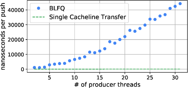
Figure 1 shows a comparison of the BLFQ when scaling the number of producers blue data points). If unsynchronized, a cache line can be transported between processing elements (PE) in to green dashed lines), but this is not achieved if that transfer must be synchronized/coordinated. Time per push rises quickly as the number of threads increases, far and above the dashed line.
This paper introduces Virtual-Link (VL) as a solution to close this communication overhead gap. VL is nearly as performant as many hardware-only solutions, while being as flexible as the most modern software queue. Instead of having threads access the shared queue state variables (i.e., head, tail, or lock) atomically, VL provides configurable hardware support for M:N communication, providing both data transfer and synchronization. Unlike other hardware queue architectures, VL reuses the existing cache coherence network and delivers a virtualized channel as if there were a direct link (or route) between two arbitrary PEs. VL facilitates efficient synchronized data movement between M:N producers and consumers with several benefits: (i) the number of sharers on synchronization primitives is reduced to zero, eliminating a primary bottleneck of traditional lock-free queues, (ii) memory spills, snoops, and invalidations are reduced, (iii) data stays on the fast path (inside the interconnect) a majority of the time.
The contributions of this work are:
-
1.
We present a characterization of communication bottlenecks existing in modern software queues based on measurements.
-
2.
We propose Virtual-Link, a hardware/software solution to eliminate the overhead of synchronization, achieving efficient synchronization between producers and consumers.
-
3.
We perform evaluation on 7 benchmarks. VL synchronization significantly improve the performance by 2.09 on average over conventional synchronization.
In the next sections, we describe how extant solutions (both lock-based and lock-free) scale on modern systems, identifying the synchronization issues to solve (§ II), then elaborate the design of VL (§ III) based on this defined problem space, and present the implementation as well as evaluation (§ IV). At the end, we compare VL with related architecture and software solutions (§ V), and lastly draw conclusions (§ VI).
II Problem Description and Motivation
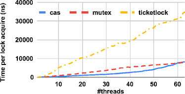
There are two integral parts in sending a message: atomicity and condition synchronization [22]. There are various means to achieve the latter (loosely ordered from complex to simple, and by no means intended to be complete): Compare-And-Swap (CAS), spin-locks, load-linked store-conditional, ticket-locks, and so on. Building on each of these mechanisms, programmers can guarantee exclusivity of access to a critical section that constitutes a region for data communication. Figure 2 shows a sweep of a CAS-based lock, a ticket-lock, and a standard spin-lock on a Platform 1 from Table IV using the open-source lockhammer [21] benchmark. Even for a CAS-based lock, after a relatively small number of threads, the overhead to acquire a lock becomes high enough to ensure programmers who want to write efficient programs stick to extremely coarse-grained parallel kernels to amortize synchronization costs.
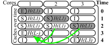
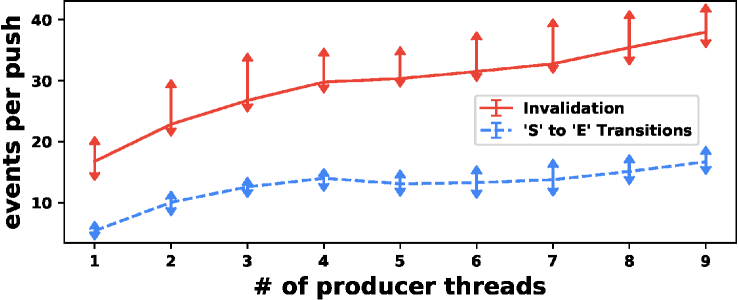
Figure 3 depicts the behavior of a single “lock” variable being operated on atomically, as is the case with CAS, by three cores. For each instance of time, (S) represents a “shared” cache state, (E) an “exclusive” state, and (I) indicates that the cache line is invalid. The (L-X) represents a lock while the X indicates which core owns the lock. The arrows from Time 2 to Time 3 represent the invalidate-acknowledge traffic that must occur before Core 1 can release the lock. It is this traffic, and therefore the number of sharers that bound synchronization performance. Figure 4 shows empirical performance counter measurements from Platform 2 from Table IV (chosen for counter availability) demonstrating that the number of invalidation events and shared to exclusive coherence state transitions increase proportionally with the number of sharers (in this case the number of producer threads). With a significant number of contending sharers, cores, and large interconnect, the time to perform a CAS operation can be sizeable. Thus, while data movement itself between cores in a coherence network is quite fast [23], updates to widely shared variables (e.g. a queue head pointer) can take a significant amount of time. Based on this observation, VL adds hardware support to manage the shared queue state, and assign unique endpoints for each producer or consumer thread to operate free of contention.
An efficient queue mechanism needs back-pressure: Real systems experience some form of transient rate mismatch between otherwise rate matched producer-consumer pairs causing “bursty” queue occupancy to be observed [24]. As such, any solution must provide a low-overhead mechanism to accommodate this behavior. Providing back-pressure when a queue is full is necessary to prevent buffer spillage to memory or overwriting of contents. Hence, we incorporate in VL a low-overhead mechanism to produce back-pressure as needed, ensuring data can stay within the cache coherence interconnect (fast-path) when possible. Without the back-pressure, programmers must increase buffer size to accommodate “bursty” behavior, increasing the probability of access to main memory (see Little’s Law [25]). We will show that VL also reduces main memory (DRAM) access, reducing communication latency and increasing efficiency (DRAM access is more expensive in terms of energy than SRAM [26]). Likewise, when arrival rates are greater than consumer service rates, back-pressure enables software to perform adjustments such as changing the PE configuration, or throttling compute kernels.
Smart cache line injection: Traditional software message queues typically load data (or shared state variables) on demand. At best, these queues rely on prefetching to ensure the data is near vs. far. A design feature driving VL’s mechanism is the ability to target and stash data to endpoints directly, e.g. the local private L1 data cache. This should result in a latency advantage ( faster [27]). Some injection mechanisms must know the target core in order to target the last level private cache (preferable [28]), other mechanisms that simply target the system-level cache [29] do not require this. When building systems that rely on knowing who the target physical cores are ahead of time, yet another layer of synchronization and complexity is added, e.g. if thread migration is allowed, every producer would need to look-up consumer targets in a shared table, likely demonstrating the same scaling shown in Figure 2. Additionally, exposing the physical core-id can be a security risk [30], e.g. a virtual-CPU typically has no idea what CPU it is actually running on [31]. Our VL design must not require the producers or the consumers to know about each other, and VL should allow direct injection (to transfer data and notify the consumer).
III Design
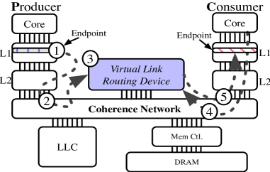
Virtual-Link (VL) accomplishes the movement of cache lines from producers to consumers by attaching a routing device (VLRD) to the coherence network as illustrated in Figure 5. The VLRD is attached to the coherence network like a tightly coupled accelerator or system cache slice, from a port on the coherence network. This VLRD enables VL to “link” unique “endpoints” together via a shared queue identifier (SQI). Endpoints subscribe to a SQI to form a M:N message channel Each SQI can support M producer endpoints and N consumer endpoints. Each unique endpoint for a SQI maintains its own local user-space buffer composed of multiple coherence granules or cache lines. Messages from each endpoint are received by the VLRD at a coherence granularity, in a lock-free manner. In abstract, VL enables a virtual linking of cache lines from each unique endpoint subscribing to a SQI so that a producer can copy-over data from its own cache lines directly into a requesting consumer through a single level of indirection.
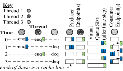
Multiple endpoints on a single SQI come together to form a Virtual Queue (VQ). Figure 6 illustrates the ordering of operations between two producer endpoints and a consumer endpoint sharing a SQI. The VQ size is shown after each time step. In Figure 6, the cache lines are moved atomically, that is at time step , the blue producer cache line data appears to be copied-over atomically (through the interconnect, not main memory) to the consumer endpoint buffer. This copy-over operation leaves the producer cache line zeroed and in an exclusive state, which can be used for subsequent enqueue operations. After the copy-over operation, the data are shipped to the consumer to dequeue, also in an exclusive state. At no point does the consumer or producer access a shared Physical Address (PA) or Virtual Address (VA) that could cause coherence traffic (snoops). Instead, threads check the endpoints owned by themselves and interact with the VLRD for synchronization. The rest of this section presents the major components of VL, namely, the VLRD, ISA extensions and system software support.
| Cyc. | Stage 1 reads linkTab (SQI head, tail) | Stage 2 makes mapping decision (hit/miss) | Stage 3 updates tables and buffers |
| 1 | \cellcolor LinkBlueprodHead1, consTail1 NULL, NULL | ||
| /* linkTab[consBuf[1].linkId], CIHR 2 */ | |||
| 2 | \cellcolor LinkOrangeprodHead1, consTail1 NULL, NULL | ||
| /* linkTab[consBuf[2].linkId], CIHR NULL */ | \cellcolor LinkBluemiss: append to the linked list in consBuf | ||
| /* because prodHead1=NULL, no blue data */ | |||
| 3 | \cellcolor LinkBlueconsHead1, prodTail1 1, 1 /* RAW */ | ||
| /* linkTab[prodBuf[1].linkId], PIHR 2 */ | \cellcolor LinkOrangemiss: append to the linked list in consBuf | ||
| /* because prodHead1=NULL, no orange data */ | \cellcolor LinkBluelinkTab[1].cons{Head, Tail} 1, 1 /* linkId2=1, CIHR2=1, new consHead read by Stage 1 */ | ||
| 4 | \cellcolor LinkGreenconsHead1, prodTail1 NULL, NULL /* linkTab[prodBuf[2].linkId], PIHR 3 */ | \cellcolor LinkBluehit: read consBuf[1] for consTgt, nextL | |
| /* consHead1=1 */ | \cellcolor LinkOrangelinkTab[0].cons{Head, Tail} 2, 2 | ||
| /* linkId2=0, CIHR2=2 */ | |||
| 5 | \cellcolor LinkBlueconsHead1 NULL /*nextL2 forwarded*/ | ||
| prodTailNULL /*linkTab[prodBuf[3].linkId]*/ | \cellcolor LinkGreenmiss: append to the linked list in prodBuf | ||
| /* because consHead1=NULL, no green request */ | \cellcolor LinkBluelinkTab[1].consHead NULL /* nextL2 */ | ||
| set prodBuf[1].OUT POHR, POTR 1, 1 |
III-A Routing Device
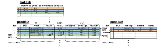
The VLRD is tasked with matching incoming messages to a SQI and stashing those messages to the subscribed consumers. As Figure 7 shows, the VLRD is largely composed of three structures, the Link Table (linkTab), the Producer Buffer (prodBuf), and the Consumer Buffer (consBuf) (some control logic is omitted for brevity). The linkTab keeps metadata (i.e., head, tail) for each SQI, one per row. The prodBuf and consBuf are shared across multiple SQI entries, and buffer producer data and consumer requests, respectively. Buffer slots are taken in turn and shared by multiple SQIs, therefore these structures cannot be used as contiguous FIFOs but instead are managed as linked-lists (LL)s.
linkTab: The head/tail pointers in linkTab each point to the first and last entries in a hardware-managed inter-leaved LL data structure, which enables hardware to determine whether there is consumer demand on a specific SQI or data available from a producer to send. The producer head (prodHead) is updated if the current head is mapped and ready to be sent to a consumer. For example in Figure 7 the green row, prodHead points to index 2 (Row 2 in prodBuf). Once index 2 is mapped with a green consumer request coming later, prodHead is set to the next green entry (4 in this example). The linkTab is addressed by the SQI field in prodBuf and consBuf.
consBuf: Whenever a consumer request arrives in the VLRD, the port’s control logic checks Consumer Input Free Register (CIFR) for a free buffer slot in order to buffer the consumer request. A buffer slot is free if the valid bit is unset, and CIFR always moves to the next free slot after a slot is taken, starting over from the first free consBuf slot again after touching the bottom. The consumer request is composed of two parts: 1) the address of the target consumer cache line (the local user-space buffer of a consumer endpoint) buffered in consTgt as shown in Figure 7; and 2) the SQI of the VQ from which data is requested. The former is the payload of the incoming packet, and latter is encoded in the device-memory physical address received through the coherence network (details in § III-C2). The nextL field together with the consHead, consTail in linkTab make LLs for SQIs. As mentioned before, the slots in consBuf is not always used in order when multiple SQIs are active. The nextIn field together with Consumer Input Head Register (CIHR) and Consumer Input Tail Register (CITR) forming a LL, so that consBuf can track the order to feed the address mapping pipeline. Address mapping pipeline stages are illustrated in Table I (explained later).
prodBuf: The Producer Buffer has three partitions, namely, IN, LINK, OUT as shown in Figure 7. On cache line arrival to the VLRD, the Producer Input Free Register (PIFR) is checked for a free buffer entry. The Producer Input Head Register (PIHR), and Producer Input Tail Register (PITR) point to the next, and the last buffered producer push waiting for address mapping, respectively. The IN partition plus the LINK partition are very similar to the consBuf, except that the data field stores the data enqueued by producers (§ III-D). The LINK partition is a LL whose head is the oldest entry ready to be sent to a consumer; the order in which producer data was received is tracked by the LL; so data are sent to consumers in the same order. The OUT partition is for registering mapped entries, i.e., entries that have been assigned to a consumer target from the process in Table I. For example, the first blue entry in the prodBuf is mapped to consBuf entry as indicated by Figure 7. The consTgt field in the OUT partition stores the result of address mapping (i.e., a target consumer cache line address), and mapped field recording an index to the mapped consBuf slot. There are also two registers associated with this partition, the Producer Output Head Register (POHR), and the Producer Output Tail Register (POTR) to track the next, and the last entry ready to send out, respectively. Each of the three partitions is a separate SRAM block with its own read/write ports, making each partition accessed independently.
Address mapping: A prodBuf entry with valid data or a consBuf entry occupied by a consumer request will go through a 3-stage pipeline illustrated in Table I, to map a producer push with a consumer pull. At the first stage the control logic takes SQI from the “head entry” (the entry pointed by either PIHR or CIHR) to access the linkTab and get the head, tail pointers of a corresponding queue. In Stage 2, a decision is made on whether to map the “head entry” to a consumer request or producer data buffered earlier. For example, in Cycle 1 the first blue consumer request reads blue prodHead, which is then checked in Cycle 2 Stage 2 in Table I. The blue request has to append to blue consumer LL upon a miss. A hit occurs in Cycle 4 Stage 2, when a blue data enters the pipeline and hits the blue consumer request. The third stage performs writes, updating table and buffers according to the mapping decision.
There are a few trade-offs making the VLRD design simpler or more complex: 1) The multiple buffer partitions decouple the address mapping pipeline and bus I/O, so a burst of packets can be buffered first then fed into the pipeline, otherwise the VLRD just accepts one packet per clock cycle; 2) LLis chosen over a bitvector to deal with the sparse buffer entry usage, that is not only due to the consideration of FIFO property, but also because the authors feel LL is more scalable for large VLRDs. Additional trade-offs are discussed in § III-C2.
III-B Instruction Set Extensions
To allow software to express the role of producer/consumer explicitly, VL adds three new instructions for vl_select, vl_push and vl_fetch operations. Technically they are “data cache” maintenance instructions with a dc nomenclature; we simply refer to them by their named function.
vl_select Rt: The vl_select identifies a specific cache line by a VA in the operand register Rt. As the name suggests, vl_select “selects” a cache line addressed by VA, so that a follow-on vl_push or vl_fetch instruction can perform its operation on the “selected” cache line. Through vl_select, the VA of the cache line is translated, and the PA gets latched into a system register (not part of context state) only accessible by vl_push or vl_fetch. Similar to load-linked store-conditional (LLSC), where a load-link always precedes a store-conditional, there is a dependency between a vl_select instruction and a vl_push or vl_fetch instruction, although vl_fetch itself can be executed speculatively and out-of-order with respect to instructions other than vl_push or vl_fetch. In the case the cache line to select has been evicted into memory, vl_select generates a cache miss and brings the cache line back to L1 data cache (L1D), just as any store would, in an “exclusive” cache state. On context swap or page migration, the latched PA is cleared.
vl_push Rs, Rt: The vl_push instruction takes the cache line from vl_select and conditionally writes it from cacheable memory to a VLRD memory target Rt (provided as a VA). This VA in Rt is assigned to the VLRD by the scheme described in § III-C2. The operand register Rs receives the result of zero for success or nonzero upon failure of a vl_push operation. On completion, the selection of the cache line ends (i.e., PA in the system register set by vl_select is zeroed). There are a few scenarios the vl_push operation could fail. First, a vl_push being called without a previous vl_select call results in a non-zero value written back to Rs. The second, is the most expected failure case where the VLRD has no buffering capacity or consumer demand which also returns a non-zero to Rs. A system register counting vl_push instructions on-the-fly ensures no context swap or interrupt can occur before a Rs receives a result. The VLRD must make forward progress in a fixed interval, i.e. bounded by the time it takes to get to the VLRD, which is approximately 14 cycles in our implementation. vl_push is a device memory write on the coherence network, as such, the write is non-snooping and it cannot be merged with other writes.
vl_fetch Rs, Rt: The vl_fetch has the effect of pulling data from a VLRD memory location (the VA from Rt) into the calling core’s private cache at the location specified by the paired vl_select call. Like vl_push, vl_fetch clears cache line selection on execution. If data is available on a given SQI (see § III-C2 for VA to VLRD and SQI mapping), then the VLRD sends a data injection to the user buffer location specified by vl_select immediately. If data is not available, the request is conditionally registered with the VLRD, conditional on buffering capacity for requests in the VLRD. A successful request results in a zero value being stored in Rs. Once data is available for the requested SQI then data is conditionally injected. vl_fetch sets a “pushable” bit within the calling core’s private caches, this facilitates asynchronous (and speculative) conditional data injection by the VLRD while ensuring data still in-use is not overwritten by the VLRD. If there is a context swap, thread migration following a vl_fetch, or the line is evicted, the injection attempt is rejected, because the “pushable” cache flag is unset before any of those scenarios occur, and the data remain with the VLRD. The system register set by vl_select is cleared by vl_fetch as well. On being scheduled the programmer is expected to check the line to see if new data has arrived (e.g. examine control region from § III-D), to re-issue the request which sets the cache tag as “pusheable” again.
The ISA described adds a single bit to the cache tag array of each private cache, and adds conditional write and push commands to support the signalling. VL uses an otherwise standard coherence network with non-snooping directed data transfer, the width of that network remains unchanged.
III-C User-space and System Software
Using an existing queuing framework such as BLFQ or ZMQ with VL is simply a matter of mapping the ISA from § III-B corresponding to enqueue/dequeue semantics to the existing software queue application program interface. There are a few additional allocation constraints, such as specific alignment requirements and VLRD setup. Hence, we develop a library to ease the programmer burden.
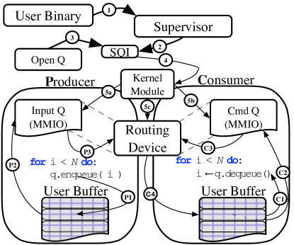
In Figure 8b, a user binary starts by requesting a SQI (equivalent to a file handle) at (1) and (2). At (3) the programmer maps this SQI into a process accessible VA through a system call at (4), that sets up the VLRD with the SQI at (5c) and returns a mapped VA into user-space at (5a) and (5b).
III-C1 SQI allocation & release
M:N endpoints assigned to a SQI are allowed to communicate. This is akin to “shared memory” Inter-Process-Communication (IPC) with the SQI being analogous to a file descriptor and following similar rules with similar supervisor/OS protections [32]. The SQI can be used to open endpoints from user-space, granting the calling thread access to map this SQI channel into its address space. Listing 9 is what is executed at (1) of Figure 8b, resulting in the SQI at (2). SQI closing and ordering semantics are identical to those of “shared” memory POSIX file handles, simplifying the programming interface.
III-C2 Endpoint creation
As shown in Figure 8b, once a SQI is obtained, the programmer must “open” the queue (3) then map that descriptor to a VA to address the assigned VLRD. This SQI is mapped to a VA using mmap [32] (via a kernel module wrapper at (5a) and (5b)) as shown in Code snippet 10 using the addressing scheme described shortly.
A user-space library can subdivide the device-memory-mapped VA page further to make multiple non-overlapping (-aligned) addresses for the same SQI within a single address space. Our implementation maps a page to each page-aligned MMIO address on the VLRD. A bit-vector within the user-space wrapper around mmap is maintained to quickly find an unused, -aligned offset to return. If PROT_WRITE is given the library call returns a producer page mapping, likewise if PROT_READ is given, a consumer page returned. Removing a user-space VA mapping for an endpoint is through the munmap command [32].
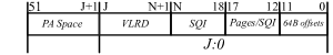
The allocated endpoint VA from mmap is the means by which vl_push is able to target the VLRD, and the PA (translated from the VA) is the means by which the VLRD can determine the SQI. Figure 11, describes the bit fields of the PA with VL information encoded. A VLRD simply takes as the SQI, while bits could distinguish different VLRDs if more than one VLRD are implemented to serve different VQs independently. Multiple pages may be used, e.g. to map into differing address spaces, or more than 64 endpoints are needed. This is what bits used for, allowing up to thirty two pages. This memory mapping process is repeated for the consumer endpoints. A downside of this process is physical address space is used, e.g. with -VLRD, and -SQIs then and which would use up of address space (not physical memory). An alternative addressing scheme that we explored adds an address table to the VLRD (populated on mmap) to map to arbitrary addresses, however, at the cost of an extra cycle to the pipeline § III-A and content addressable memory for the routing table.
III-C3 User-space buffer creation
VL enables both producers and consumers to use any page-aligned cacheable memory as the user-space buffer for local endpoints (e.g. the data source at (1) from Figure 5). The memory could be obtained from any generic memory allocation functions (e.g. posix_memalign). The capacity of these buffers can be adjusted in user-space without impacting VL to accommodate bursty behavior or non-stationary queue traffic distributions. It is these user-space memory buffers that are used in subsequent enqueue and dequeue operations (§ III-D). The user-space buffer for each endpoint is used as a circular buffer for sending lines to the VLRD, as such it will typically be kept cache-local. Once a line from the user-space buffer is pushed to the VLRD, it is marked as cleaned, (e.g. reset control region as discribed in § III-D), so that it is ready for follow-on enqueue operations.
III-D Enqueue and dequeue
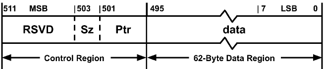
Figure 6 shows the queue order per single SQI atomically pushing a cache line size messages from M:N producer/consumer pairs. Messages larger than a cache line can be incorporated via indirect buffers as pointers. While not demonstrated in this paper, it is trivial to incorporate an existing indirect buffer format such as VirtIO 1.1 [33], injection could be accelerated in this case by [34]. To facilitate small message transfer, we embed cache line local queue state into the line itself (see Figure 12). This consists of a control region at the Most Significant Byte (MSB) of each VL transported cache line. the remaining are user-data/payload. Valid data fills the data region from higher address towards Least Significant Byte (LSB). Within the control region, 2b encodes for size, e.g., byte, half word, word, double word. 6b encodes a cache line relative offset/head pointer. The remaining is reserved.
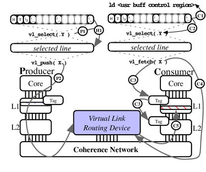
enqueue: With respect to Figure 8a, the enqueue operation calls vl_select at (P1) on an allocated user-space buffer (). The user-space cacheable memory transitions to a “selected” state at (H1) that causes this cache line’s VA to be translated and latched. The follow-on vl_push instruction at (P2) causes the cache line at the aforementioned latched PA from vl_select () to be stored to the mapped VLRD device-memory address (). Assuming the conditional store was successful, the original cache-able user-space memory from is owned by the VLRD. This order of events is necessary to prevent a single instruction from requiring two address generations simultaneously. If the enqueue succeeds, the cache line is zeroed, otherwise the return register (see § III-B) is set appropriately so that the programmer can retry pushing the same data at some future point.
dequeue: Dequeue operations for VL are essentially operations that set a cache line as “pushable” while also notifying the VLRD that of data is requested at a specific cacheable-memory VA. With respect to Figure 8a, the dequeue operation calls vl_select at (C2) on an allocated user-space consumer buffer, after determining at (C1) that no more data is available (e.g. by inspecting the control region). Calling vl_select at (C2) sets that VA and latches the PA of that line for a follow-on vl_fetch instruction (§ III-B). As described in § III-B, vl_fetch sets a “pushable” flag at (C3) for the cache line addressed by the previous vl_select statement. Following the setting of the “pushable” flag, vl_fetch causes the target PA and core-id to be registered with the VLRD at (C4). That registered PA is used when data becomes available for a given SQI for a follow-on injection of data to the requester at (C5).
IV Evaluation
IV-A Experimental Methodology
We evaluate Virtual-Link with 7 benchmarks listed in Table II. To capture a wide range of communication and synchronization patterns, we chose to evaluate several kernels from the Ember [35] benchmark suite: ping-pong, halo, sweep, and incast. FIR is a typical digital signal processing workload that pipelines data through several filter stages. The overhead of fine-grained pipelining for FIR has spawned several field programmable gate array implementations [36]. Bitonic sorting algorithm [37] is a good candidate for fine-grained parallelization. The pipeline [38] benchmark emulates network package processing and has a mix of different queue patterns. All benchmarks are compiled using gcc-8.2.0 and optimization level ‘-O3’. For all experiments, affinity is set to reduce unnecessary noise from thread migration. A state-of-the-art software queue implementation, Boost Lock Free Queue (BLFQ version 1.63) is set as the baseline. We also compare VL to ZMQ (version 4.2.1), another popular software queue implementation.
All the experiments, unless noted, are performed using gem5 [39], with VL hardware support implemented as extensions to an AArch64 architecture. Table III summarizes key simulator settings.
| Benchmark | Description, (M:N) producer:consumer channel |
|---|---|
| ping-pong [35] | data back and forth between two threads (1:1) |
| halo [35] | exchange data with neighboring threads (1:1) |
| sweep [35] | data sweeps through a grid of threads corner to corner (1:1) |
| incast [35] | all threads sending data to the master thread (15:1) |
| FIR | data streams through 32-stage FIR filter (1:1) |
| bitonic [37] | bitonic sort with varying number of threads (1:N)(M:1) |
| pipeline [38] | 4-stage pipeline with middle stages multi-threaded (1:4)(4:4)(4:1) (1:1) |
| Cores | 16 AArch64 OoO CPU @ |
|---|---|
| Caches | private 2-way L1D, private 3-way L1I |
| shared 16-way mostly-inclusive L2 | |
| Memory | DDR4 |
| VLRD | 64 entries per prodBuf, consBuf, and linkTab (about in total) |
| Platform Processor | Memory | OS | ||
|---|---|---|---|---|
| 1 |
|
DDR4-3200 | Linux 5.4 | |
| 2 |
|
DDR4-2133 | ||
IV-B Results and Analysis
In Figure 13, we compare VL with two state-of-the-art software queues, BLFQ as baseline and ZMQ. In addition to this, we add VL(ideal) which has infinity queue capacity and zero-latency cache line transfers in order to show that those hardware limitations do not put much overhead on VL. Each VL run is given with buffer entries, and denoted as VL64.
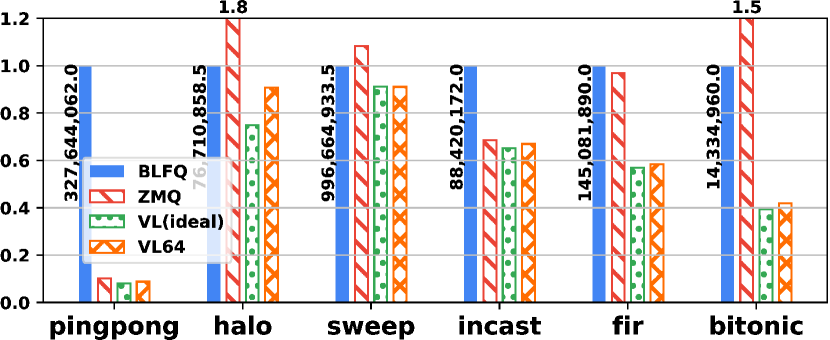
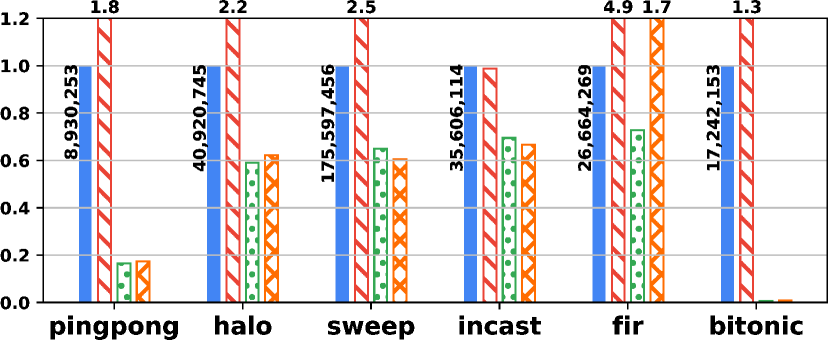
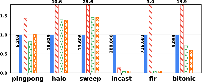
In Figure 13a we see that VL is on average faster than software solutions, ranging from faster for ping-pong to faster for sweep. ZMQ falls somewhere in between on all benchmarks, though notably being slower on halo and bitonic, which both favor low-latency small message traffic. However, on incast and FIR, BLFQ builds up a long queue spilling to memory (many more memory transactions in Figure 13c), ZMQ and VL both have a back-pressure mechanism so get better performance. Figure 13b shows the relative magnitude of snoop transactions initiated per benchmark and with queue schemes. VL has fewer snoops than either of the two software queues (BLFQ and ZMQ). The only exception FIR has two threads per core creating many context switches, which lead to more frequent failures for VLRD’s attempts to deliver cache lines. Software queues suffer from more snoop transactions due to cache coherence (as discussed in § II), while Virtual-Link reduces the snoop traffic to a minimum as it reduces the cache coherent state shared between communicating threads. Figure 13c compares the amount of memory transactions between queues. Overall, VL has the fewest memory transactions among the queuing schemes. VL and ZMQ are significantly lower on incast and FIR with the help of the back-pressure mechanism. On ping-pong and bitonic, VL also achieves about 20% reduction compared to BLFQ, while ZMQ has more memory transactions. VL has more memory transactions on halo, and sweep, because the benchmarks double buffer the communication channels and not all the buffers are managed by our provided queuing libraries, but by the application.
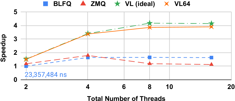
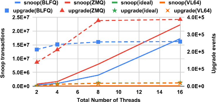
Scalability: Bitonic has a fixed workload divided among a varying number of worker threads. Figure 14 presents the scalability of bitonic with various queue implementations as the number of worker threads are changed (1, 3, 7, and 15 worker threads plus one master thread dispatching tasks to worker threads). Initially, ZMQ performs better than BLFQ with small numbers of threads (i.e., 2, 4), but ZMQ’s performance drops after 8 threads. The high overhead to maintain cache coherence (as shown in Figure 15) degrades the performance of ZMQ. Because BLFQ does CAS operations, it scales slightly better than ZMQ, however, neither scale as well as VL. BLFQ stops scaling by 4 threads. In contrast, VL is still able to gain speedup moving from 4 threads to 8 threads. At 8 threads, the computation part of the single master thread dominates the execution time and become the bottleneck; that is why none of the queuing mechanisms can help any more. In Figure 15, we present one big difference between VL and the other software queues at a microarchitecture level, to better understand why they scale differently. Both the BLFQ and ZMQ software implementations have more cache line upgrade events than VL, and the rate of snoop traffic synchronization goes more rapidly. VL has very few upgrades and snoops, therefore it is able to scale better than BLFQ and ZMQ (see Figure 3).
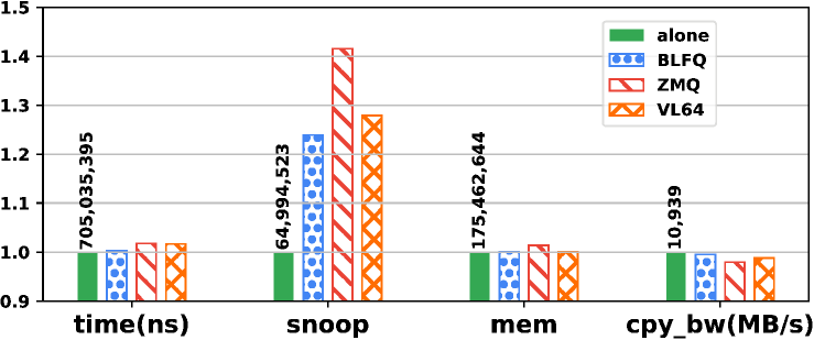
Coherence traffic interference: VL channels use the coherence network for moving data between cores. This could impact the coherence traffic patterns and hurt the performance of other applications that do not use VL. To study the impact of VL on coherence traffic, we ran the STREAM benchmark [40] concurrently with ping-pong using each queue implementation (BLFQ, ZMQ, VL). STREAM was chosen as it is known to stress the memory hierarchy. Figure 16 shows that the execution time for each queue implementation (BLFQ, ZMQ, VL) varied by or less when compared to STREAM executing alone. The other three bar groups report the system snoop and memory traffic. The snoop traffic introduced by VL is comparable to that of BLFQ, and significantly lower than that of ZMQ.
Area estimation: We developed RTL code for the VLRD (control logic + buffers), synthesized it using the Synopsys Design Compiler with the FreePDK library [41], and scaled the design to using [42] for comparison purposes. The resulting VLRD area is for buffers and in total including control logic. To put this into perspective, an Arm A-72 core at 16FF is [43]; our design is of the single-core area, however, each VLRD is meant to serve cores. A -core Arm A- configuration (like our simulation), excluding L2 caches and wire overhead, would be approximately . Based on this estimation, our VLRD shared by 16 cores, would occupy less than of overall SoC area (adding caches and wire area would only improve this ratio).
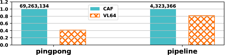
Comparison with CAF: CAF [38] is a state-of-the-art hardware queue proposal similar to VL with a couple of differences: i. CAF divides buffers between queues and applies advanced credit management for QoS, while buffers in VLRD are shared by all queues; ii. The enqueue/dequeue operations in CAF transfer 64-bit values between registers and Queue Management Device, whereas VL exploits cache lines as local buffer and as such lowers the frequency of performing relatively more costly data movement through the cache hierarchy. We compare VL with CAF on two benchmarks used in CAF paper, ping-pong and pipeline: ping-pong passes data through the queue, while pipeline uses the queue for pointers to network packet payloads. As shown in Figure 17, VL achieves speedup over CAF on ping-pong, and speedup on pipeline.
V Related Work
Software IPC ranges from POSIX standard IPC (e.g. mkfifo [32]) to user-space libraries such as the BLFQ [19] (a more complete survey can be found in [44]). Instead of focusing on improving the algorithms, VL focuses on hardware-software codesign, arriving at a solution that combines the flexibility of software with hardware acceleration.
IPC is closely related, even synonymous, to message-passing (including MPI), data-flow, stream-processing, and many other topics. MPI, generically, is a topic of constant research, recent works [45, 46, 47] in particular focus on reducing core-to-core latency. These works expose very low-level tuning knobs to the programmer assuming the programmer can better tune an application. Our work on the other hand focuses on maintaining the same programming semantics expected by even novice parallel programmers while reducing Dataflow processing, is closely related to systolic array processing, stream processing, and Coarse-grained Reconfigurable Array (CGRA) processing. Loosely, the aforementioned topics are collected together as they all aim to allow maximum exploitation of spatial communication patterns, allowing each PE to send data directly to down-stream dataflow targets [48, 49]. Dataflow connections forming communications links are often direct register-to-register transfers mediated by a common bus (e.g., [11, 12, 13] and many others summarized by [50, 51]). Systolic arrays are also a form of dataflow, although with a fixed spatial communication pattern, e.g. [52, 53, 54]. Closely related to the above are CGRAs [55]. Each work differs slightly in the amount of reconfiguration permitted, from the least flexible systolic array to the most flexible CGRA. Unlike these, VL can exploit spatial locality of data streams while having dynamic software configurable connectivity.
Modern core-to-core communication concepts, occupy a spectrum from direct memory transfer instructions to various hardware-software schemes. Network processing cores such as TILE64 [14], DSP-like processors such as the IBM Cell [15], and the Freescale DPAA [16] provide channel operators or primitives to send data from PE-to-PE. Works such as HAQu [56] which uses two new structures per-core, including a Queue Local Table, whereas with VL, the logic is simpler and located within the interconnect, enabling any type of device to theoretically connect and use VL. HAQu decentrialized head and tail pointers to each core, by doing so it made M:N communications difficult to implement. CAF [38] and Intel DLB [57], went in a different direction, centralizing the queue management enabling M:N. VL goes in a different direction entirely, focusing on minimalism in implementation while enabling M:N and decentralized head and tail pointers. Other works, such as [58] focus on specific use-cases in Android, whereas VL intends to be more generic.
VI Conclusion
In this paper, we presented Virtual-Link (VL) an inter-process communication (IPC) mechanism for fine-grained multi-threaded applications. VL is immune to cache contention for synchronization, provides back-pressure to reduce memory spills, and achieves low-latency cache injection by directly stashing the line into consumer L1D cache. This novel cross-core synchronization mechanism is similar to software queue mechanisms in flexibility but has the performance and efficiency of hardware solutions. Our full-system gem5 simulation illustrated that we can obtain a speedup and average reduction in memory traffic over state-of-the-art software solutions across a variety of communications patterns and benchmarks.
References
- [1] R. H. Dennard, F. H. Gaensslen et al., “Design of ion-implanted MOSFET’s with very small physical dimensions,” IEEE Journal of Solid-State Circuits, vol. 9, no. 5, pp. 256–268, 1974.
- [2] L. B. Kish, “End of moore’s law: thermal (noise) death of integration in micro and nano electronics,” Physics Letters A, vol. 305, no. 3-4, pp. 144–149, 2002.
- [3] J. S. Vetter, R. Brightwell et al., “Extreme heterogeneity 2018-productive computational science in the era of extreme heterogeneity: Report for doe ascr workshop on extreme heterogeneity,” USDOE Office of Science (SC), Washington, DC (United States), Tech. Rep., 2018.
- [4] A. Kleen, “Linux multi-core scalability,” in Proceedings of Linux Kongress, 2009.
- [5] E. W. Dijkstra, “A solution of a problem in concurrent programming control,” September 1965.
- [6] L. Lamport, “How to make a multiprocessor computer that correctly executes multiprocess progranm,” IEEE transactions on computers, no. 9, pp. 690–691, 1979.
- [7] D. C. Arvind and G. Maa, “Assessing the benefits of fine-grain parallelism in dataflow programs,” International Journal of High-performance Computing Applications, vol. 2, no. 3, 1988.
- [8] “Ampere reveals “quicksilver” altra lineup, 128-core “mystique” kicker,” https://bit.ly/2Hiqj3D, accessed: 2020-07-21.
- [9] D. Pasetto, M. Meneghin et al., “Performance evaluation of interthread communication mechanisms on multicore/multithreaded architectures,” in Proceedings of the 21st international symposium on High-Performance Parallel and Distributed Computing, 2012, pp. 131–132.
- [10] H. Akkan, M. Lang et al., “Hpc runtime support for fast and power efficient locking and synchronization,” in 2013 IEEE International Conference on Cluster Computing. IEEE, 2013, pp. 1–7.
- [11] V. G. Grafe, G. S. Davidson et al., “The epsilon dataflow processor,” ACM SIGARCH Computer Architecture News, vol. 17, no. 3, pp. 36–45, 1989.
- [12] G. M. Papadopoulos and D. E. Culler, “Monsoon: an explicit token-store architecture,” in ACM SIGARCH Computer Architecture News, vol. 18, no. 2SI. ACM, 1990, pp. 82–91.
- [13] M. D. Noakes, D. A. Wallach et al., “The j-machine multicomputer: An architectural evaluation,” ACM SIGARCH Computer Architecture News, vol. 21, no. 2, pp. 224–235, 1993.
- [14] S. Bell, B. Edwards et al., “Tile64 - processor: A 64-core soc with mesh interconnect,” in 2008 IEEE International Solid-State Circuits Conference - Digest of Technical Papers, Feb 2008, pp. 88–598.
- [15] T. Chen, R. Raghavan et al., “Cell broadband engine architecture and its first implementation—a performance view,” IBM Journal of Research and Development, vol. 51, no. 5, pp. 559–572, 2007.
- [16] D. QorIQ, “Primer for software architecture,” Technical report, Freescale Semiconductor Inc, Tech. Rep., 2012.
- [17] E. Ladan-Mozes and N. Shavit, “An optimistic approach to lock-free fifo queues,” in International Symposium on Distributed Computing. Springer, 2004, pp. 117–131.
- [18] O. Michel, J. Sonchack et al., “Packet-level analytics in software without compromises,” in 10th USENIX Workshop on Hot Topics in Cloud Computing (HotCloud 18), 2018.
- [19] “Class template queue,” https://bit.ly/37hAMHJ, accessed: 2020-08-19.
- [20] P. Hintjens, “Zeromq: the guide,” URL http://zeromq. org, 2010.
- [21] “lockhammer,” https://bit.ly/3kbvz7N, accessed: 2020-07-21.
- [22] M. L. Scott, “Shared-memory synchronization,” Synthesis Lectures on Computer Architecture, vol. 8, no. 2, pp. 1–221, 2013.
- [23] M. M. Martin, M. D. Hill et al., “Why on-chip cache coherence is here to stay,” Communications of the ACM, vol. 55, no. 7, pp. 78–89, 2012.
- [24] M. Harchol-Balter, Performance modeling and design of computer systems: queueing theory in action. Cambridge University Press, 2013.
- [25] D. Bertsimas and D. Nakazato, “The distributional little’s law and its applications,” Operations Research, vol. 43, no. 2, pp. 298–310, 1995.
- [26] H. Jiang, X. Peng et al., “Cimat: A compute-in-memory architecture for on-chip training based on transpose sram arrays,” IEEE Transactions on Computers, 2020.
- [27] E. A. León, R. Riesen et al., “Cache injection for parallel applications,” in Proceedings of the 20th international symposium on High performance distributed computing, 2011, pp. 15–26.
- [28] A. AMBA, “Amba-5 architecture specification,” https://bit.ly/356Sjjf, 2020, accessed: 2020-10-13.
- [29] A. Farshin, A. Roozbeh et al., “Reexamining direct cache access to optimize i/o intensive applications for multi-hundred-gigabit networks,” in 2020 USENIX Annual Technical Conference, 2020, pp. 673–689.
- [30] Z. Huang, “A comparative study on the performance isolation of virtualization technologies,” Ph.D. dissertation, Arizona State University, 2019.
- [31] J. Rao, K. Wang et al., “Optimizing virtual machine scheduling in numa multicore systems,” in 2013 IEEE 19th International Symposium on High Performance Computer Architecture. IEEE, 2013, pp. 306–317.
- [32] The open group base specifications issue 7, 2018 edition ieee std 1003.1-2017 (revision of ieee std 1003.1-2008). https://bit.ly/2Hfww0w. Accessed October 2020.
- [33] Virtual I/O Device (VIRTIO) Version 1.1. https://bit.ly/3jaEqWf. Accessed October 2019.
- [34] Revere-AMU System Architecture, Arm Limited, September 2019. [Online]. Available: https://bit.ly/3kajJuQ
- [35] “Ember communication pattern library,” https://bit.ly/3k9egUV, accessed: 2020-10-13.
- [36] J. B. Evans, “Efficient fir filter architectures suitable for fpga implementation,” IEEE Transactions on Circuits and Systems II: Analog and Digital Signal Processing, vol. 41, no. 7, pp. 490–493, 1994.
- [37] K. E. Batcher, “Sorting networks and their applications,” in Proceedings of the April 30–May 2, 1968, spring joint computer conference, 1968, pp. 307–314.
- [38] Y. Wang, R. Wang et al., “Caf: Core to core communication acceleration framework,” in 2016 International Conference on Parallel Architecture and Compilation Techniques (PACT). IEEE, 2016, pp. 351–362.
- [39] N. Binkert, B. Beckmann et al., “The gem5 simulator,” SIGARCH Comput. Archit. News, vol. 39, no. 2, p. 1–7, Aug. 2011. [Online]. Available: https://doi.org/10.1145/2024716.2024718
- [40] J. D. McCalpin et al., “Memory bandwidth and machine balance in current high performance computers,” IEEE computer society technical committee on computer architecture newsletter, vol. 2, no. 19–25, 1995.
- [41] J. E. Stine, I. Castellanos et al., “Freepdk: An open-source variation-aware design kit,” in 2007 IEEE International Conference on Microelectronic Systems Education (MSE’07), 2007, pp. 173–174.
- [42] A. Stillmaker and B. Baas, “Scaling equations for the accurate prediction of cmos device performance from 180nm to 7nm,” Integration, vol. 58, pp. 74 – 81, 2017. [Online]. Available: http://www.sciencedirect.com/science/article/pii/S0167926017300755
- [43] “Inside ARM’s Cortex-A72 microarchitecture,” https://bit.ly/3sf0a9h, accessed: 2021-01-09.
- [44] M. Herlihy, N. Shavit et al., The art of multiprocessor programming. Newnes, 2020.
- [45] J. Jose, M. Luo et al., “Unifying upc and mpi runtimes: experience with mvapich,” in Proceedings of the Fourth Conference on Partitioned Global Address Space Programming Model, 2010, pp. 1–10.
- [46] N. Hjelm, “An evaluation of the one-sided performance in open mpi,” in Proceedings of the 23rd European MPI Users’ Group Meeting, 2016, pp. 184–187.
- [47] H. P. Pritchard Jr, T. Naughton et al., “Getting it right with open mpi: Best practices for deployment and tuning of open mpi,” Los Alamos National Lab.(LANL), Los Alamos, NM (US), Tech. Rep., 2020.
- [48] J. B. Dennis, “Data flow supercomputers,” Computer, no. 11, pp. 48–56, 1980.
- [49] A. Arvind and K. P. Gostelow, “The u-interpreter,” Computer, no. 2, pp. 42–49, 1982.
- [50] B. Lee and A. R. Hurson, “Issues in dataflow computing,” in Advances in computers. Elsevier, 1993, vol. 37, pp. 285–333.
- [51] A. R. Hurson and K. M. Kavi, “Dataflow computers: Their history and future,” Wiley Encyclopedia of Computer Science and Engineering, 2007.
- [52] D. A. Pomerleau, G. L. Gusciora et al., “Neural network simulation at warp speed: How we got 17 million connections per second,” CMU, Tech. Rep., 1988.
- [53] W. J. Dally, F. Labonte et al., “Merrimac: Supercomputing with streams,” in Proceedings of the 2003 ACM/IEEE conference on Supercomputing. IEEE, 2003, pp. 35–35.
- [54] N. Jouppi, C. Young et al., “Motivation for and evaluation of the first tensor processing unit,” IEEE Micro, vol. 38, no. 3, pp. 10–19, 2018.
- [55] J. Gray and T. Kean, “Configurable hardware: a new paradigm for computation,” in Proceedings, 10th Cultech. Conference on VLSI, 1993, pp. 279–295.
- [56] S. Lee, D. Tiwari et al., “Haqu: Hardware-accelerated queueing for fine-grained threading on a chip multiprocessor,” in 2011 IEEE 17th International Symposium on High Performance Computer Architecture. IEEE, 2011, pp. 99–110.
- [57] “Queue Management and Load Balancing on Intel® Architecture,” https://intel.ly/3hY0Zy8, accessed: 2021-01-09.
- [58] D. Du, Z. Hua et al., “XPC: architectural support for secure and efficient cross process call,” in Proceedings of the 46th International Symposium on Computer Architecture, 2019, pp. 671–684.