Present address: ]OnePlanet Research Center, Bronland 10, 6708 WH Wageningen, The Netherlands
An atomic Faraday beam splitter for light generated from pump degenerate four-wave mixing in a hollow-core photonic crystal fiber
Abstract
We demonstrate an atomic Faraday dichroic beam splitter suitable to spatially separate signal and idler fields from pump degenerate four-wave mixing in an atomic source. By rotating the plane of polarization of one mode with respect to the other, a subsequent polarizing beam splitter separates the two frequencies, which differ by only 13.6 GHz, and achieves a suppression of and dB in the two outputs, with a corresponding transmission of 97 and 99 %. This technique avoids the need to use spatial separation of four-wave mixing modes and thus opens the door for the process efficiency to be enhanced in waveguide experiments. As a proof-of-principle we generate light via four-wave mixing in 87Rb loaded into a hollow-core photonic crystal fiber and interface it with the atomic Faraday dichroic beam splitter.
I Introduction
Non-linear optical effects are well known to be greatly enhanced when guided through optical fibers, due to both high-intensities and large interaction lengths which far exceed the Rayleigh length [1]. The use of hollow-core photonic crystal fibers (HC-PCFs) [2] conveniently allows the light mode to interface with a gas [3] or liquid medium [4] of choice. When loaded with a highly resonant medium, such as an atomic gas, the HC-PCF system shows pronounced non-linear effects at low powers. Electromagnetically induced transparency [5], four-wave mixing [6], cross-phase modulation [7], photon memories [8] and singe-photon sources [9] have all been shown to be enhanced with an atomic gas loaded HC-PCF system.
In recent years four-wave mixing (FWM) in atomic vapours has received considerable attention because it allows the generation of narrowband non-classical light [10, 11, 12, 13, 14] which is naturally compatible with other atom-based applications such as single-photon storage [15, 16, 17]. Pump degenerate FWM [10, 11, 18], where the two pump photons have the same frequency, allows for a simplified experimental setup because only one laser is needed to pump the medium. Therefore, pump-degenerate FWM should be more applicable as a quantum technology. However, to achieve a high spectral brightness in a free-beam configuration, high-power solid state lasers are used [11] which are cumbersome and expensive. A boost in efficiency will be required to allow simple low-power diode lasers to take over the role as the pump and push the system into the realm of practical quantum technology. For this HC-PCFs could be used, since they allow the FWM effect to occur over a much increased path length, and the efficiency scales with this length squared [19].
The hollow-core fiber system, however, presents a challenge for filtering the different frequencies since the signal, idler and pump fields are all spatially overlapping. The pump field is cross-polarized with respect to the signal and idler fields, however a subsequent polarizer will not sufficiently remove the pump field, additional methods are required [11, 20]. In this paper we show that by using isotopically pure 87Rb as the FWM medium, the pump field can be removed from the output by using a subsequent isotopically pure 85Rb cell which is resonant with the pump. The 85Rb cell is thus used as an ultra-narrow notch filter which allows the signal and idler fields to pass. This leaves the challenge of separating the signal and idler fields from each other. Since these fields have the same polarization, their frequency difference (just twice the ground state hyperfine splitting) is the only degree of freedom with which to separate them. We show that the Faraday effect in another atomic vapour can be used as the beam splitter. We achieve the separation of signal and idler modes by rotating the plane of polarization of one mode by 90∘ with respect to the other.
The Faraday effect in atomic vapours can be strong. High Verdet constants have being demonstrated [21] with minimal absorption. Given that this effect is highly frequency dependent and strongest when close to an atomic transition, it is commonly used to create ultra-narrow bandpass filters (see ref. [22] and references therein). However, only a few examples have been shown where the Faraday effect was used as a beam splitter [23, 24]. In this study we show that computational optimisation can be used to design the Faraday dichroic beam splitter (FDBS), and we experimentally show that it achieves unprecedented transmission and purity in both output ports.
Furthermore, as a proof-of-principle, we describe a pump-probe experiment where light generated from 87Rb atoms loaded into a HC-PCF was interfaced with the FDBS. We show that we can use the FDBS to estimate the ratio of FWM to Raman processes responsible for the gain seen in the pump-probe experiment.
II Theory and background
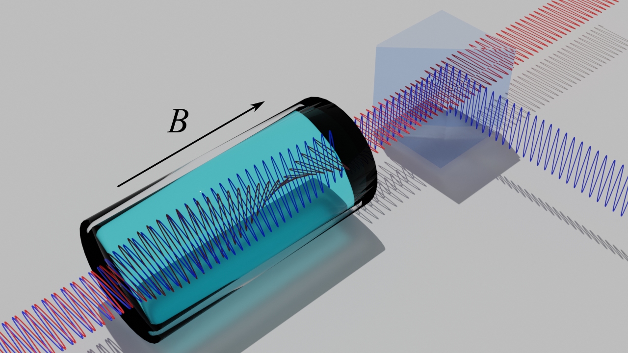
The concept of an FDBS is illustrated in Fig. 1. Two different frequencies of light, with the same polarization, are incident on an atomic vapour cell. An axial magnetic field () causes circular birefringence in the atomic medium, which in turn causes a rotation of the plane of polarization (the Faraday effect [25]). Due to the strong frequency dependence of the circular birefringence, the two frequencies of light will have their plane of polarization rotated by different amounts. If the difference in polarization after the vapour cell is then the two frequencies can be perfectly separated at a polarizing beam splitter. It should be noted that the magnetic field will also induce differential absorption between the circular components of linearly polarized light (circular dichroism), which means the light emerging from the cell cannot remain entirely linearly polarized, but rather elliptically polarized. Therefore perfect separation is impossible with linear polarizing beam splitters, however, since absorption decreases with detuning from resonance faster than dispersion [26], the effect of circular dichroism can be minimised while keeping a substantial circular birefringence. It is for this reason that it is possible for the light to remain almost linearly polarized while exhibiting significant Faraday rotation.
The challenge is to engineer the properties of the atomic vapour such that the difference in Faraday rotation is as close to as possible while maximising transmission at the two frequencies. In a thermal atomic medium, the transmission and dispersion spectra can be modelled very accurately in the weak-probe regime [27]. Simple analytical expressions for the Faraday rotation signals can be used when far off resonance [28, 29], since Doppler broadening and hyperfine structure can be ignored [26]. However, when on or near resonance, simple analytical expressions cannot be used due to the large number of partially overlapping transitions of varying strengths, which create a complicated spectrum. We use a well established model, that has proven to be highly accurate for predicting absorption and dispersion spectra for alkali-metal vapours [30, 31, 27]. To compute the model have chosen to use the open source ElecSus program [32, 33]. A description of the underlying model is given in ref. [32].
Various experimental parameters such as the strength of the -field, it’s orientation with respect to the light propagation axis, cell temperature (), cell length, and angle of the polarizers will all affect the output of the dichroic beam splitter device. In principle all of these parameters can be optimised by computational means [34, 35, 36]. To decrease computation time we choose to only keep and as parameters and fix all the other degrees of freedom. Furthermore, we consider only an axial magnetic field, and also only the case where the final polarizer is aligned to the input light polarization for maximum transmission (defined here as the -direction). The length of the vapour is fixed to 2 mm because this length is short enough to allow high-strength, uniform magnetic fields to be achieved conveniently with permanent magnets (up to 10 kG [37]).
III Design by computational optimisation
Effective optimisation is achieved by careful design of a cost function which captures the deviation from optimal working conditions. This cost function is then minimised while changing the magnetic field and temperature to find these optimal working parameters. High transmission and high purity in each output is desired, and as such the following cost function is used:
| (1) |
where and are the components of the light intensity exiting the vapour cell of orthogonal linear polarizations, and and are the two frequencies of interest. Note that if there is either a complete loss of light or no frequency discrimination (i.e ) the cost function reaches a maximum value of zero. The minimum value of -4 is only achieved when there is both full transmission and complete separation of the two frequencies. Also, since it is unimportant from which output the two frequency components emerge, the cost function is evaluated for both cases ( and ) with the smaller taken.
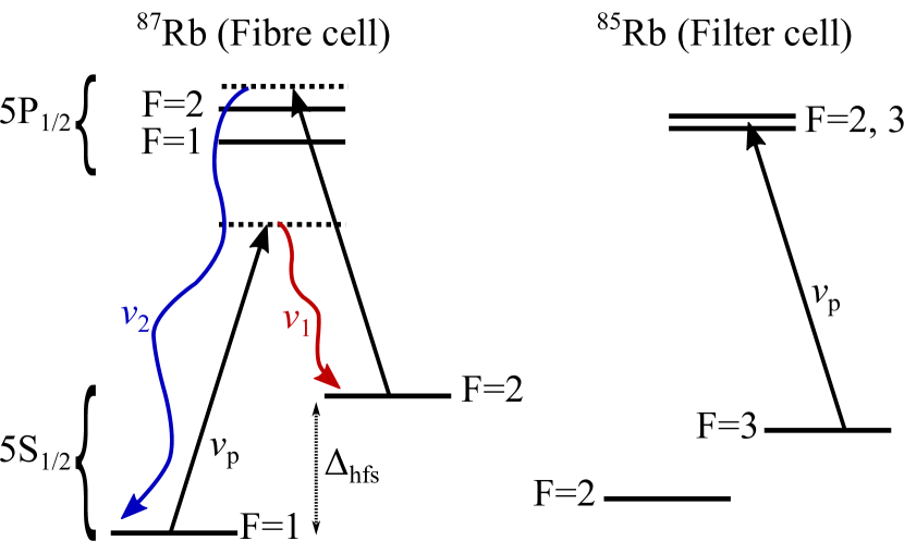
The frequencies and were chosen for this study by considering the case of light generated in 87Rb gas from a double-lambda scheme, as shown in figure 2. A pump laser is blue detuned approximately 0.8 GHz detuned from the transition on the D1 line. This scheme has been chosen because it is close enough to resonance to show significant emission at the frequencies and , which complete the double lambda scheme, while allowing the pump light to be eliminated by subsequent cell containing isotopically pure 85Rb. This results in the frequencies to separate being at detuning values of -8.23 and 5.43 GHz from the Rb D1 global linecentre of 377.107407 THz [32].
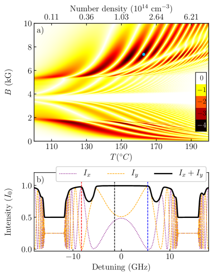
The cost function is efficiently minimised by employing a carefully constructed global fitting routine [35]. However, to illustrate the structure of the cost function we have chosen to map it in detail over the a large parameter range, from 100 to 200 ∘C and from 0 to 10 kG. The result for an isotopically pure 85Rb cell is shown in panel a) of figure 3. There are many minima seen emphasising the need for a global optimisation routine. A key feature of the map is that the minima are somewhat periodic in number density which is simply explained by solutions occurring for Faraday rotation angles () that occur at approximately for one frequency and for the other. Another feature is that minima are seen for two magnetic field domains, kG and kG. In the lower field domain the magnetic shift of the atomic lines is small and as such the atomic transitions occur between and . In the higher field regime the magnetic shift is now such that the strong atomic transitions lie outside of the region between and . In both these regimes it is possible to achieve a near 90∘ differential Faraday rotation with little absorption. However, in between these magnetic field regimes the atomic transitions coincide with one or more of the frequencies of interest, causing absorption and creating ellipticity in the output light, and therefore increasing the cost function.
The global optimal solution () is found at a cell temperature of 162.8C and magnetic field of kG. At this high magnetic field the atoms are in the Hyperfine Paschen-Back regime [38, 21, 39, 40, 41]. The transmission spectrum of the vapour and its polarization components in the - and -direction are shown in panel b) of figure 3. The spectra are almost symmetrical around the weighted linecentre, a common feature of the hyperfine-Paschen Back regime. Also, at this high temperature the vapour is highly circularly dichroic at detunings of approximately GHz, being optically thick for one circular polarization while being transparent for the other. This results in transmission values of approximately 0.5 in these regions with the resulting and intensities being almost 0.25. Panel b) of figure 3 also clearly shows high transmission into the channel for and high transmission into the channel for .
IV Experimental results
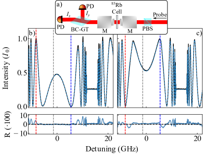
To experimentally test the solution found by computational optimisation, the FDBS was constructed and tested with weak probe laser spectroscopy. A 2 mm long vapour cell was surrounded with two permanent ring magnets to apply large magnetic field. The magnets were custom designed to give a near uniform magnetic field which matched the optimal value found. Due to manufacturing tolerance, subsequent small adjustments of the magnetic field is needed to match the magnetic field. This was achieved by both adjusting the magnets’ separation and their temperatures. A weak probe beam from an external cavity diode laser was then sent through a polarizing beam splitter cube (PBS) before passing through the vapour cell and then being incident on a Brewster-cut Glan-Taylor polarizing beam splitter (BC-GT). The intensity of the transmitted () and reflected () beams from the BC-GT were then measured with amplified photodetectors. Before heating the vapour cell, the PBS and BC-GT were aligned such that the laser power was maximised through the transmission port of the BC-GT and minimised at its reflection port. The use of the BC-GT as an analyzer improves the polarization purity in the reflected port by reducing reflection of p-polarized light. When measured with an optically thin, room-temperature vapour cell, we found the extinction ratios for the whole setup between the two polarizers to be dB and dB for the and outputs respectively.
The cell was then heated. After the setup reached thermal equilibrium the laser was scanned and five spectra were recorded in quick succession. An example spectrum is visible in figure 4, along with a fit using ElecSus [32, 33]. We see good agreement between experiment and theory with an RMS deviation of 2 %. From fitting the five spectra we find a magnetic field of kG and a temperature of C, where the uncertainties represent the standard deviation in the fit parameters over the five spectra.
The difference between the optimal parameters and these measured ones are very small and should not cause any significant degradation in performance.
These results experimentally confirm that we achieve high transmission into at , and high transmission into at as predicted. Using the fitted theoretical spectra we can also predict the spectral purity in each channel by calculating the extinction ratios,
| (2) | ||||
which were found to be and dB for and respectively. Note that these extinction ratios are calculated assuming perfect polarizers and no birefringence from the cell windows. For the experimental measurements however, our laser spectroscopy method is not precise enough to give a useful comparison with theory. For this measurement, we instead use a technique similar to lock-in amplification, where the laser frequency is fixed to one of the frequencies of interest () while modulating the laser with an optical chopper. Using a Fourier transform we take the signal power at the chopper frequency only and thereby remove the effect of noise at all other frequencies. In this way we get a more precise measure of and . Repeating the process at the other frequency of interest gives a measurement of and . Figure 5 shows the result of this measurement. From this data we calculate dB, dB, where the uncertainties are derived from the uncertainty in the change in laser power after changing its frequency. These extinction ratios are smaller in magnitude than the theoretical best values which could be due to a small drift in the cell temperature during the time taken to change the laser frequency. Nevertheless, for the purpose of heralded single photon sources, the residual impurity would only negligibly decrease the heralding efficiency.

V Separation of light from four-wave mixing in a HC-PCF
In this section a proof-of-principle experiment is described where the Faraday beam splitter is used to separate light generated by seeded four-wave mixing from thermal 87Rb atoms in a HC-PCF. We use a kagome structured hollow-core photonic crystal fiber with a m core diameter and a length of 10 cm. More details about the fibre used are given in ref. [42]. The fiber is fully encapsulated within a borosilicate glass cell containing isotopically purified Rb vapour (isotopic ratio: 98.8 % 87Rb, 1.2 % 85Rb). Fiber-cells of this type show fast fiber filling times at tens of minutes [43, 44] compared to fibers mounted in steel based vacuum chambers which can take months to fill [42]. The fiber-cell system also benefits from having a persistent high optical depths without light induced atomic desorption, which has been exploited for steel-based vacuum chamber systems [45, 46].
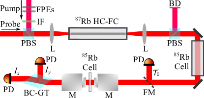
A diagram of the experimental arrangement is shown in figure 6. An external cavity diode laser (ECDL) is used for the pump beam and is fixed to be resonant with the Doppler broadened transition in 85Rb. The pump passes through two solid etalons and an interference filter which serve to greatly suppress broadband emission from the laser diode which is outside of the lasing wavelength. The probe beam comes from another ECDL and is scanned approximately GHz around the D1 weighted linecentre. The pump beam is overlapped with the probe beam inside the hollow-core fiber. The pump and probe have a power of 1.5 mW and W inside the fiber. The two beams are orthogonally polarized and a polarizing beam splitter (PBS) cube after the fiber cell transmits the probe while removing approximately 99 % of the pump light. The pump at this point is still over two orders of magnitude stronger at than the signal and idler fields, and so a heated 75 mm long 85Rb cell is used to eliminate the pump. We detected no remaining pump light even when using single photon counting modules, and from these measurements we estimate the pump light to have a power of less than fW. Also we estimate the loss on the signal and idler fields, due to imperfect AR-coatings and scattering in the atomic vapour, to only be less than . After passing the 75 mm long 85Rb cell, a flipper mirror can then be used to measure the probe at this point or direct the beam to the FDBS setup.
Panel a) of figure 7 shows the measured transmission spectrum after the first two vapour cells () but before the FDBS. Gain features are seen when the probe is near the two-photon resonance frequencies, and . Near a peak transmission of 1.15 is seen. Previous similar experiments using a bulk vapour cells with lengths approximately 10 times shorter, show gain at a similar order of magnitude with hundreds of mW of pump power [47]. This is in line with the length squared enhancement in efficiency expected [19], however the relatively small mode due to the fiber-core size means we are working at much higher intensities. The gain peak around exhibits Autler-Townes splitting and a light shift [48] of approximately 200 MHz of the strongest peak. Competition between FWM gain and Raman absorption near means the gain peak is somewhat suppressed and the spectrum is more complicated due to these additional features [10]. Both the gain features around the two-photon resonances show significant power broadening, but nevertheless, the relatively broadband Faraday rotation features of the FDBS capture much of the light across the gain bandwidths.
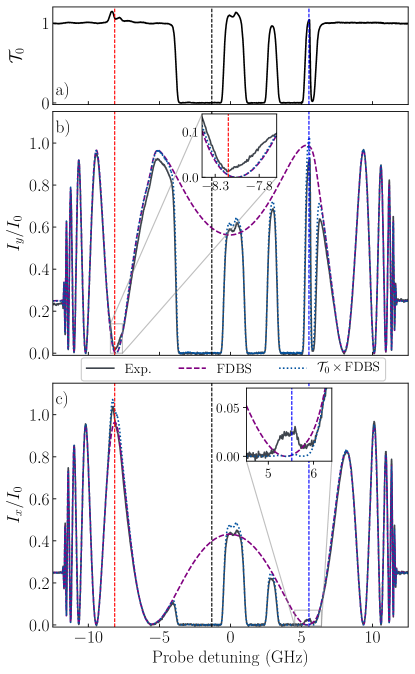
The gain features observed can be the result of FWM or Raman processes. Using the FDBS we can distinguish between the two processes. This is because Raman processes do no produce observable light at any other frequencies other than that of the probe and therefore the overall spectral response after should simply be the product of the spectra from individual cells, i.e. , where denotes the intensity spectra for the FDBS device only. Any measured deviation from this simple product is evidence for light having been produced at another frequency. Panels b) and c) of figure 7 show the and outputs after the probe has traversed the FDBS. Deviations are indeed seen, however, due to the laser power changing throughout the scan there is a residual error of up to 5 % of our estimate of the initial intensity spectrum . This means that deviations across some parts of the spectrum are simply measurement artefacts. However, the effect of this measurement error is almost entirely suppressed around the regions where the spectra are near zero. The insets in panels b) and c) of figure 7 shows an expanded view around the two-photon resonances for the outputs where almost no light should be seen for those probe detuning values. A clear excess of approximately 2 % is seen in both cases, which indicates light having been generated from FWM. From these results we can estimate that 20 % of the gain observed is due to FWM while 80 % is from Raman scattering. For a heralded single photon source, this level of Raman scattering would significantly degrade the performance since it is a source of photons in the two channels which are uncorrelated. Further work is necessary to ascertain the reason for the low proportion of photon pairs from FWM compared to Raman scattering, but it is likely to be due to a loss of ground state coherence from the atoms colliding with the fiber walls, despite the fact that the thin walls of the kagome structured fibers have shown some anti-relaxation properties [49]. A solution could be to introduce a buffer gas to the fiber cells, which should dramatically increase the ground state coherence [50].
VI Conclusions and outlook
We have presented a Faraday dichroic beam splitter designed to separate signal and idler fields from a four-wave mixing process in 87Rb. The device exploits the Faraday effect in a rubidium atomic vapour to rotate the plane of polarization of one frequency more than another. Using computational optimization with a tailored cost function, we have found the optimal magnetic field and temperature of the vapour cell to give excellent transmission and separation of the two frequencies. The device has been tested experimentally with the atomic vapour found to transmit at 97 and 99 % of light for the lower and higher frequency channel respectively, with corresponding extinction ratios of and dB. Furthermore, we applied the Faraday dichroic beam splitter in an envisaged use case, namely that of separating signal and idler fields from four-wave mixing in a 87Rb medium loaded into a hollow-core fiber, which precludes using spatial separation from phase matching to separate the two fields. This allowed the estimation of the amount of four-wave mixing occurring in relative to that Raman scattering, which we found at a ratio of 1:5. We expect that if the Raman scattering can be suppressed, the Faraday dichroic beam splitter could be used to observe heralded single photons from the 87Rb loaded hollow-core fiber system.
Acknowledgements.
The authors thank F. Schreiber for technical support in constructing the fiber cells, and N. Y. Joly and P. St. J. Russell of the Max Planck Institute for the Science of Light (Erlangen) for providing the hollow-core photonic crystal fiber. This project has received funding from the European Union’s Horizon 2020 research and innovation programme under the Marie Sklodowska-Curie grant agreement No 789642.References
- Benabid et al. [2005] F. Benabid, F. Couny, J. C. Knight, T. A. Birks, and P. St. J. Russell, Compact, stable and efficient all-fibre gas cells using hollow-core photonic crystal fibres, Nature 434, 488 (2005).
- Russell [2003] P. Russell, Photonic Crystal Fibers, Science 299, 358 (2003).
- Debord et al. [2019] B. Debord, F. Amrani, L. Vincetti, F. Gérôme, and F. Benabid, Hollow-Core Fiber Technology: The Rising of “Gas Photonics”, Fibers 7, 16 (2019).
- Horan et al. [2012] L. E. Horan, A. A. Ruth, and F. C. Garcia Gunning, Hollow core photonic crystal fiber based viscometer with Raman spectroscopy, J. Chem. Phys. 137, 224504 (2012).
- Ghosh et al. [2006] S. Ghosh, A. R. Bhagwat, C. Kyle Renshaw, S. Goh, A. L. Gaeta, and B. J. Kirby, Low-Light-Level Optical Interactions with Rubidium Vapor in a Photonic Band-Gap Fiber, Phys. Rev. Lett. 97, 023603 (2006).
- Londero et al. [2009] P. Londero, V. Venkataraman, A. R. Bhagwat, A. D. Slepkov, and A. L. Gaeta, Ultralow-Power Four-Wave Mixing with Rb in a Hollow-Core Photonic Band-Gap Fiber, Phys. Rev. Lett. 103, 043602 (2009).
- Perrella et al. [2013] C. Perrella, P. S. Light, J. D. Anstie, F. Benabid, T. M. Stace, A. G. White, and A. N. Luiten, High-efficiency cross-phase modulation in a gas-filled waveguide, Phys. Rev. A 88, 013819 (2013).
- Sprague et al. [2014] M. R. Sprague, P. S. Michelberger, T. F. M. Champion, D. G. England, J. Nunn, X.-M. Jin, W. S. Kolthammer, A. Abdolvand, P. St. J. Russell, and I. A. Walmsley, Broadband single-photon-level memory in a hollow-core photonic crystal fibre, Nat. Photonics 8, 287 (2014).
- Cordier et al. [2020] M. Cordier, P. Delaye, F. Gérôme, F. Benabid, and I. Zaquine, Raman-free fibered photon-pair source, Sci. Rep. 10, 1650 (2020).
- McCormick et al. [2007] C. F. McCormick, V. Boyer, E. Arimondo, and P. D. Lett, Strong relative intensity squeezing by four-wave mixing in rubidium vapor, Opt. Lett. 32, 178 (2007).
- MacRae et al. [2012] A. MacRae, T. Brannan, R. Achal, and A. I. Lvovsky, Tomography of a High-Purity Narrowband Photon from a Transient Atomic Collective Excitation, Phys. Rev. Lett. 109, 033601 (2012).
- Shu et al. [2016] C. Shu, P. Chen, T. K. A. Chow, L. Zhu, Y. Xiao, M. M. T. Loy, and S. Du, Subnatural-linewidth biphotons from a Doppler-broadened hot atomic vapour cell, Nat. Commun. 7, 12783 (2016).
- Whiting et al. [2017] D. J. Whiting, N. Šibalić, J. Keaveney, C. S. Adams, and I. G. Hughes, Single-Photon Interference due to Motion in an Atomic Collective Excitation, Phys. Rev. Lett. 118, 253601 (2017).
- Ripka et al. [2018] F. Ripka, H. Kübler, R. Löw, and T. Pfau, A room-temperature single-photon source based on strongly interacting Rydberg atoms, Science 362, 446 (2018).
- Julsgaard et al. [2004] B. Julsgaard, J. Sherson, J. Ignacio Cirac, J. Fiurášek, and E. S. Polzik, Experimental demonstration of quantum memory for light., Nature 432, 482 (2004).
- Hosseini et al. [2011] M. Hosseini, B. M. Sparkes, G. Campbell, P. K. Lam, and B. C. Buchler, High efficiency coherent optical memory with warm rubidium vapour, Nat. Commun. 2, 174 (2011).
- Michelberger et al. [2015] P. S. Michelberger, T. F. M. Champion, M. R. Sprague, K. T. Kaczmarek, M. Barbieri, X. M. Jin, D. G. England, W. S. Kolthammer, D. J. Saunders, J. Nunn, and I. A. Walmsley, Interfacing GHz-bandwidth heralded single photons with a warm vapour Raman memory, New J. Phys. 17, 043006 (2015).
- Podhora et al. [2017] L. Podhora, P. Obšil, I. Straka, M. Ježek, and L. Slodička, Nonclassical photon pairs from warm atomic vapor using a single driving laser, Opt. Express 25, 31230 (2017).
- Bratfalean and Ewart [1996] R. Bratfalean and P. Ewart, The dependence of broadband four-wave mixing signal intensity on the length of the interaction region, J. Mod. Opt. 43, 2523 (1996).
- Palittapongarnpim et al. [2012] P. Palittapongarnpim, A. MacRae, and A. I. Lvovsky, Note: a monolithic filter cavity for experiments in quantum optics, Rev. Sci. Instrum. 83, 066101 (2012).
- Weller et al. [2012a] L. Weller, K. S. Kleinbach, M. A. Zentile, S. Knappe, I. G. Hughes, and C. S. Adams, Optical isolator using an atomic vapor in the hyperfine Paschen–Back regime, Opt. Lett. 37, 3405 (2012a).
- Gerhardt [2018] I. Gerhardt, How anomalous is my Faraday filter?, Opt. Lett. 43, 5295 (2018).
- Abel et al. [2009] R. P. Abel, U. Krohn, P. Siddons, I. G. Hughes, and C. S. Adams, Faraday dichroic beam splitter for Raman light using an isotopically pure alkali-metal-vapor cell, Opt. Lett. 34, 3071 (2009).
- Portalupi et al. [2016] S. L. Portalupi, M. Widmann, C. Nawrath, M. Jetter, P. Michler, J. Wrachtrup, and I. Gerhardt, Simultaneous Faraday filtering of the Mollow triplet sidebands with the Cs-D1 clock transition, Nat. Commun. 7, 13632 (2016).
- Faraday [1846] M. Faraday, I. Experimental Researches in Electricity. Nineteenth Series, Philos. Trans. R. Soc. London 136, 1 (1846).
- Siddons et al. [2009] P. Siddons, C. S. Adams, and I. G. Hughes, Off-resonance absorption and dispersion in vapours of hot alkali-metal atoms, J. Phys. B: At. Mol. Opt. Phys. 42, 175004 (2009).
- Weller et al. [2012b] L. Weller, T. Dalton, P. Siddons, C. S. Adams, and I. G. Hughes, Measuring the Stokes parameters for light transmitted by a high-density rubidium vapour in large magnetic fields, J. Phys. B: At. Mol. Opt. Phys. 45, 055001 (2012b).
- Wu et al. [1986] Z. Wu, M. Kitano, W. Happer, M. Hou, and J. Daniels, Optical determination of alkali metal vapor number density using Faraday rotation, Appl. Opt. 25, 4483 (1986).
- Kemp et al. [2011] S. L. Kemp, I. G. Hughes, and S. L. Cornish, An analytical model of off-resonant Faraday rotation in hot alkali metal vapours, J. Phys. B: At. Mol. Opt. Phys. 44, 235004 (2011).
- Siddons et al. [2008] P. Siddons, C. S. Adams, C. Ge, and I. G. Hughes, Absolute absorption on rubidium D lines: comparison between theory and experiment, J. Phys. B: At. Mol. Opt. Phys. 41, 155004 (2008).
- Weller et al. [2011] L. Weller, R. J. Bettles, P. Siddons, C. S. Adams, and I. G. Hughes, Absolute absorption on the rubidium D1 line including resonant dipole–dipole interactions, J. Phys. B: At. Mol. Opt. Phys. 44, 195006 (2011).
- Zentile et al. [2015a] M. A. Zentile, J. Keaveney, L. Weller, D. J. Whiting, C. S. Adams, and I. G. Hughes, ElecSus: A program to calculate the electric susceptibility of an atomic ensemble, Comput. Phys. Commun. 189, 162 (2015a).
- Keaveney et al. [2018a] J. Keaveney, C. S. Adams, and I. G. Hughes, ElecSus: Extension to arbitrary geometry magneto-optics, Comput. Phys. Commun. 224, 311 (2018a).
- Kiefer et al. [2014] W. Kiefer, R. Löw, J. Wrachtrup, and I. Gerhardt, Na-Faraday rotation filtering: The optimal point, Sci. Rep. 4, 6552 (2014).
- Zentile et al. [2015b] M. A. Zentile, J. Keaveney, R. S. Mathew, D. J. Whiting, C. S. Adams, and I. G. Hughes, Optimization of atomic Faraday filters in the presence of homogeneous line broadening, J. Phys. B: At. Mol. Opt. Phys. 48, 185001 (2015b).
- Keaveney et al. [2018b] J. Keaveney, S. A. Wrathmall, C. S. Adams, and I. G. Hughes, Optimized ultra-narrow atomic bandpass filters via magneto-optic rotation in an unconstrained geometry, Opt. Lett. 43, 4272 (2018b).
- Reed et al. [2018] D. J. Reed, N. Šibalić, D. J. Whiting, J. M. Kondo, C. S. Adams, and K. J. Weatherill, Low-drift Zeeman shifted atomic frequency reference, OSA Continuum 1, 4 (2018).
- Sargsyan et al. [2012] A. Sargsyan, G. Hakhumyan, C. Leroy, Y. Pashayan-Leroy, A. Papoyan, and D. Sarkisyan, Hyperfine Paschen-Back regime realized in Rb nanocell, Opt. Lett. 37, 1379 (2012).
- Weller et al. [2012c] L. Weller, K. S. Kleinbach, M. A. Zentile, S. Knappe, C. S. Adams, and I. G. Hughes, Absolute absorption and dispersion of a rubidium vapour in the hyperfine Paschen–Back regime, J. Phys. B: At. Mol. Opt. Phys. 45, 215005 (2012c).
- Zentile et al. [2014] M. A. Zentile, R. Andrews, L. Weller, S. Knappe, C. S. Adams, and I. G. Hughes, The hyperfine Paschen–Back Faraday effect, J. Phys. B: At. Mol. Opt. Phys. 47, 075005 (2014).
- Sargsyan et al. [2015] A. Sargsyan, A. Tonoyan, G. Hakhumyan, C. Leroy, Y. Pashayan-Leroy, and D. Sarkisyan, Complete hyperfine Paschen-Back regime at relatively small magnetic fields realized in potassium nano-cell, EPL 110, 23001 (2015).
- Epple et al. [2014] G. Epple, K. S. Kleinbach, T. G. Euser, N. Y. Joly, T. Pfau, P. St. J. Russell, and R. Löw, Rydberg atoms in hollow-core photonic crystal fibres, Nat. Commun. 5, 4132 (2014).
- Gutekunst [2016] J. Gutekunst, EIT Spectroscopy in Hollow Core Fibers, Master thesis, University of Stuttgart (2016).
- Gutekunst et al. [2017] J. Gutekunst, D. Weller, H. Kübler, J.-P. Negel, M. A. Ahmed, T. Graf, and R. Löw, Fiber-integrated spectroscopy device for hot alkali vapor, Appl. Opt. 56, 5898 (2017).
- Kaczmarek et al. [2015] K. T. Kaczmarek, D. J. Saunders, M. R. Sprague, W. S. Kolthammer, A. Feizpour, P. M. Ledingham, B. Brecht, E. Poem, I. A. Walmsley, and J. Nunn, Ultrahigh and persistent optical depths of cesium in Kagomé-type hollow-core photonic crystal fibers, Opt. Lett. 40, 5582 (2015).
- Donvalkar et al. [2015] P. S. Donvalkar, S. Ramelow, S. Clemmen, and A. L. Gaeta, Continuous generation of rubidium vapor in hollow-core photonic bandgap fibers, Opt. Lett. 40, 5379 (2015).
- Pooser et al. [2009] R. C. Pooser, A. M. Marino, V. Boyer, K. M. Jones, and P. D. Lett, Quantum correlated light beams from non-degenerate four-wave mixing in an atomic vapor: the D1 and D2 lines of 85Rb and 87Rb, Opt. Express 17, 16722 (2009).
- Cohen-Tannoudji [1996] C. N. Cohen-Tannoudji, The Autler-Townes Effect Revisited, in Amazing Light (Springer, New York, NY, 1996) pp. 109–123.
- Bradley [2013] T. D. Bradley, Atomic vapours filled hollow core photonic crystal fibre for magneto-optical spectroscopy, Ph.D. thesis, University of Bath (2013).
- Brandt et al. [1997] S. Brandt, A. Nagel, R. Wynands, and D. Meschede, Buffer-gas-induced linewidth reduction of coherent dark resonances to below 50 Hz, Phys. Rev. A 56, R1063 (1997).