Gravitational-wave physics with Cosmic Explorer: limits to low-frequency sensitivity
Abstract
Cosmic Explorer (CE) is a next-generation ground-based gravitational-wave observatory concept, envisioned to begin operation in the 2030s, and expected to be capable of observing binary neutron star and black hole mergers back to the time of the first stars. Cosmic Explorer’s sensitive band will extend below , where the design is predominantly limited by geophysical, thermal, and quantum noises. In this work, thermal, seismic, gravity-gradient, quantum, residual gas, scattered-light, and servo-control noises are analyzed in order to motivate facility and vacuum system design requirements, potential test mass suspensions, Newtonian noise reduction strategies, improved inertial sensors, and cryogenic control requirements. Our analysis shows that with improved technologies, Cosmic Explorer can deliver a strain sensitivity better than down to . Our work refines and extends previous analysis of the Cosmic Explorer concept and outlines the key research areas needed to make this observatory a reality.
I Introduction
The second-generation of laser interferometric gravitational-wave observatories — Advanced LIGO [1], Advanced Virgo [2], and Kagra [3] — have opened a new window on the universe by observing gravitational waves from merging systems of black holes [4, 5] and neutron stars [6], and have ushered in a new era in multi-messenger astronomy [7]. Dozens of coalescing binary systems have been observed thus far [8, 9], with rapid alerts delivering sky locations and probable system types [10], bringing the features of the underlying astrophysical populations into focus. An enhancement to Advanced LIGO, known as LIGO A+, with improved quantum noise and optical coatings, is now being implemented [11]. Additionally, research and development is underway toward a cryogenic silicon detector, LIGO Voyager, that could be implemented in the existing LIGO facilities [12], and a concept for a high-frequency-focused Australian observatory is being developed [13].
A vision is developing for a global third-generation (3G) network of ground-based gravitational-wave observatories capable of observing gravitational waves across cosmic time, with nearby systems detected with incredible precision [14, 15]. The European concept for a third-generation observatory is the Einstein Telescope (ET) [16], a triangular underground observatory combining three high-power room-temperature interferometers sensitive at high frequency and three cryogenic silicon interferometers sensitive at low frequency. A United States concept for a 3G observatory is Cosmic Explorer [17, 18, 19], a L-shaped, single-interferometer observatory built on the Earth’s surface.
We anticipate a staged approach to Cosmic Explorer, similar to the approach adopted by LIGO, in which the facility hosts successive generations of detectors, each exploiting the most advanced technology available at the time. We envision that the first detector, Cosmic Explorer 1 (CE1), will operate in the 2030s using LIGO A+ technology scaled up to the increased dimensions of the facility, and with a few modest improvements. For the 2040s, the state-of-the-art technology is more difficult to predict. In this work we consider two possible designs for this detector, called Cosmic Explorer 2 (CE2). One possibility is that CE2 is a further extension of LIGO A+ technology, retaining room-temperature fused silica test masses and a laser as the working technology. Another possibility is that CE2 is an extension of the LIGO Voyager technology, employing silicon test masses at and a laser. In the rest of the paper, we will refer to detectors based on room temperature fused silica test masses and laser wavelength as the “ technology” and those with cryogenic silicon test masses and laser wavelength as the “ technology.” For both CE1 and CE2, the detector designs target observations above , while Einstein Telescope targets observations down to .
This paper presents an assessment of the low-frequency sensitivity of CE1 and CE2 based on recent research and development progress. We first present the basic low-frequency observational capabilities of Cosmic Explorer (Section II) and discuss broadly the limits to the Cosmic Explorer strain sensitivities (Section III). We then describe the Cosmic Explorer facility (Section IV) and go into detail about low-frequency noise sources (Section V). Then in Section VI we take stock of the research and development that will be required to realize Cosmic Explorer and we look forward to future work. Appendix A summarizes the different technologies used in the two stages of Cosmic Explorer and Appendix B compares the displacement and force noises of Cosmic Explorer with those of other detectors.
II Astrophysics

| Observatory | / | |||
|---|---|---|---|---|
| aLIGO | ||||
| Voyager | ||||
| CE1 | ||||
| CE2 | ||||
| ET |
Cosmic Explorer has a range of science goals, which together take advantage of the instrument’s full broadband sensitivity up to several kilohertz. Here we focus on the detection of compact binary signals. The low-frequency sensitivity affects the reach of the instrument for heavy and high-redshift signals, as well as the total signal-to-noise ratio of all compact-binary signals. The optimal signal-to-noise ratio for a particular frequency-domain signal , measured in a detector with a strain sensitivity and a gravitational-wave sensitivity band extending down to a low-frequency cutoff , is obtained when the signal is detected with a matched filter, yielding an amplitude signal-to-noise ratio given by [21, 22, 23].
For light systems (e.g., neutron stars) which are still in their inspiral phase at frequencies , improving the low-frequency cutoff has a modest but noticeable improvement on the total signal-to-noise ratio: for the idealized case of a detector with a flat noise floor down to a lower cutoff frequency , the matched-filter signal-to-noise ratio scales as , since in the stationary phase approximation [24]. This scaling amounts to roughly a improvement as the cutoff frequency is halved. On the other hand, the improvement in the amount of early warning for these inspiraling systems can be significant: the time before a coalescing system merges is related (again in the stationary-phase approximation) to the gravitational-wave frequency by [23]. Therefore, sufficiently loud signals will accumulate threshold signal-to-noise ratio soon after entering the sensitivity band, leading to an early warning time . This means that halving the low-frequency cutoff increases the early warning time more than sixfold. Fig. 1 shows the accumulation of signal-to-noise ratio found by computing , with in this case chosen to correspond with a 1.4+1.4 binary system at (luminosity distance ). By setting a threshold SNR of 8, the corresponding early warning time can be solved for, and is given in Table 1 for the detector sensitivities shown in Fig. 2.
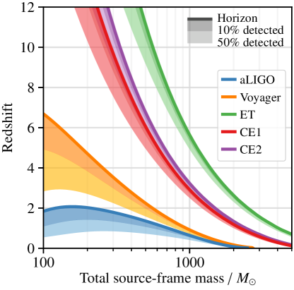
Low-frequency sensitivity is especially impactful for the detection of intermediate-mass black holes in the range . Detecting these systems at redshifts approaching 10 would provide information on the oldest population of stars (Population III). Additionally, these detections could demonstrate that supermassive black holes—approaching and exceeding —were formed by accretion and hierarchical mergers from Population III remnants (the so-called “light seed” scenario) [25]. Fig. 3 shows the response distance [26] — the redshift out to which binary black hole systems can be detected — for Cosmic Explorer and other detectors. Computing the response distance for a threshold signal-to-noise ratio requires numerically solving for the corresponding threshold ; here is the redshifted (i.e., detector-frame) gravitational waveform, which is obtained from the source-frame waveform by the substitutions111These scalings are valid if the detector does not significantly move, due to the earth’s rotation and orbit around the sun, while the signal is in that detector’s sensitivity band. This approximation is valid for Cosmic Explorer, since is sufficiently high, but not for spaced-based detectors such as LISA. , , and [27]. Table 1 summarizes the detection prospects for high-redshift, intermediate-mass black hole mergers.
III Strain sensitivity

Our Cosmic Explorer models adopt the dual-recycled Fabry–Pérot Michelson interferometer topology now employed by advanced detectors shown in Fig. 4. In brief, these detectors are Michelson interferometers whose arms are enhanced by the inclusion of partially transmissive input mirrors, turning the arms into Fabry–Pérot cavities. Then, a power-recycling mirror is placed between the laser and the beamsplitter to critically couple the Fabry–Pérot arms to the laser, which maximizes the circulating arm power. Additionally, a signal extraction mirror between the beamsplitter and the output port is used to broaden the bandwidth of the instrument [28]. Squeezed vacuum states are reflected off of a filter cavity and injected into the antisymmetric port of the interferometer in order to achieve broadband quantum noise reduction.
The upper limit to the achievable bandwidth of Cosmic Explorer is defined by the free spectral range of the arms, given by . We take the lower limit to be ; this is not a precisely motivated cutoff, but comes from our expectation of significant noise from local gravity fluctuations at a few hertz from the atmosphere, and (if Advanced-LIGO-like suspensions are used) from thermal, seismic, and control noise. The rest of the present work is concerned primarily with the geophysical and thermal noises, leaving a detailed discussion of other noises to later works.
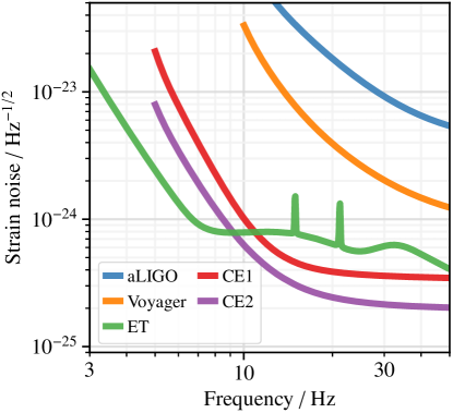
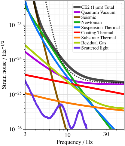
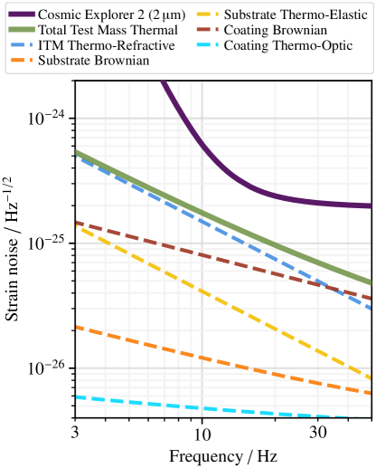
Since the initial exploration of the Cosmic Explorer sensitivity [17], many of the estimates of the fundamental noises have been refined, and some new noise sources have been considered. Figs. 5 and 6 show the updated low-frequency limits to the spectral sensitivity for CE1 and CE2, respectively, and some of the key sources of noise that contribute to these limits; the curves from the previous sensitivity study are also included. For CE1, updates with respect to previous work mean that the instrument attains strain noise better than above about , whereas the instrument presented in previous work attained this performance only above . For CE2, strain noise below is achieved around compared to in previous work; additionally, the noise performance around is slightly degraded for CE2. The primary differences from this initial work are as follows.
-
•
The ground motion of the Cosmic Explorer facility is assumed to be lower than the LIGO facilities above , based on long-term seismic surveys from some promising locations around the United States (Section IV). This lowers both the seismic noise, and the seismic component of the Rayleigh-wave Newtonian noise.
-
•
CE1 assumes tenfold better seismic isolation than Advanced LIGO at , and CE2 assumes one hundredfold better seismic isolation than Advanced LIGO at (Section V.2).
-
•
The Newtonian noise estimates now include contributions from seismic body waves and atmospheric infrasound (Section V.3), and CE1 assumes twofold suppression of ambient Rayleigh waves. Together with the reassessment of the ground motion, we find that suppression of Rayleigh and body waves is needed for CE2 to meet the sensitivity quoted in [17].
-
•
Phase noise induced by light propagation in the bulk of the input test masses is now included; this constitutes a potentially non-negligible noise source for the CE2 technology (Section V.4).
-
•
The force noise caused by the residual gas molecules in the test mass chambers striking the test masses is now included (Section V.6).
-
•
The possibility of building a room temperature CE2 with technology was not previously considered. Such a detector would have non-negligible coating thermal noise around and thus slightly worse performance than the technology and the estimate from previous work at these frequencies (Section V.4).
-
•
The suspensions for both detectors have been enlarged to of total height (previously they were ) and of total mass (previously they were ), and optimized for minimal thermal and seismic noise given updated mechanical constraints on the strength of the materials (Section V.1).
-
•
Preliminary considerations of the scattered light noise (Section V.7) and control system noise (Section V.8) suggest that these noises can be rendered subdominant within the gravitational-wave band.
IV The Cosmic Explorer facility
Many of the limits to Cosmic Explorer sensitivity at low frequency depend on assumptions about the Cosmic Explorer facility and environment. In this section we lay down requirements for the ground motion and seismic wave content (Section IV.1), the atmospheric infrasound spectrum (Section IV.2), and the ultra-high vacuum system (Section IV.3). This list is not exhaustive; for example, magnetic requirements are not discussed because the coupling of local magnetic fields depends primarily on technical details of the detector’s electronics, which are difficult to estimate without detailed modeling. Similar topics are being considered for the underground Einstein Telescope facility [29].
IV.1 Ground motion
Ground motion limits the performance of gravitational-wave interferometers both through the mechanical coupling from the ground to the suspension point of the test mass and through the direct gravitational attraction of the ground on the test mass (the so-called “Newtonian noise”) [31]. Additionally, ground motion transferred to the beam tube can cause noise from stray light.
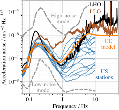
The location of Cosmic Explorer is not yet known, but an assumption for the local ground seismicity can be made based on publicly available seismic data and on the noise environment from existing facilities. To get long-term trends that encompass diurnal and seasonal variations in ground motion, we examined noise histograms from selected USArray [32] and ANSS [33] seismic stations in the western United States; these stations were chosen for their proximity to promising Cosmic Explorer candidate sites which have favorable topographic properties. We also examined noise histograms from the LIGO Hanford and Livingston sites. Above a few hertz, the ground motion of the LIGO sites is dominated by on-site machinery. In particular, heating, ventilation and air conditioning systems dominate from [34]. We assume that it will be possible to design the Cosmic Explorer infrastructure to better isolate the interferometer from such machinery by moving the vibration sources out of the experimental buildings, putting them on dampers or on pedestals mounted separately and deeply into the ground. The Cosmic Explorer ground noise model is shown in Fig. 7; this model assumes that above , the ground acceleration noise is no more than .
A complete estimate of the Newtonian noise requires a model of the seismic wave amplitude spectra and an understanding of their propagation through the ground. In general, surface seismic motion is usually assumed to be dominated by surface waves (Rayleigh and Love waves) as opposed to body waves (P and S waves), although the actual composition depends on the particular site and may additionally include higher-order surface waves [35]. Because the Cosmic Explorer site is not known, we adopt a model in which the site is Rayleigh-wave dominated above , with a flat body-wave spectrum of amplitude composed equally of P waves, vertically polarized S waves, and horizontally polarized S waves.222Love waves are not considered because they do not occur in a homogeneous and isotropic elastic half-space; moreover, Love waves do not produce Newtonian noise because their motion is a horizontal shear. Newtonian noise is generated from only the Rayleigh, P, and vertically polarized S waves, because these waves either cause a vertical displacement of the ground surface or density fluctuations of the bulk. The P-, S-, and Rayleigh-wave speeds are assumed to be , , , respectively. These parameters, and the assumptions on the wave content of the ground motion, will have to be revised once the future Cosmic Explorer site is selected and characterized.
IV.2 Atmospheric fluctuations
Newtonian noise from density fluctuations in the atmosphere is likely to impact the strain sensitivity of third-generation detectors. For Cosmic Explorer, the relevant mechanism is expected to be the propagation of infrasound (sound at frequency ) in the vicinity of the test masses. Global infrasound surveys provide noise histograms up to slightly below [36]; based on the median noise model, we take the outdoor infrasound spectrum for Cosmic Explorer to be . The choice of the median infrasound background means that, while it may be possible to find a site with lower infrasound background, we are not reliant on finding an exceptional site in order to realize the noise performance described herein. The impact of atmospheric infrasound on the detector strain sensitivity is discussed in Section V.3.2.
Other mechanisms of atmospheric noise generation include spatially varying temperature fields that move near the test mass due to wind, and pressure fluctuations generated by turbulent mixing (the aeroacoustic effect), but these noise sources are unlikely to be significant above [31]. Finally, details of the dimension and shape of the buildings housing the test masses can alter the above noise sources (e.g., by excluding large density fluctuations close to the test masses), but have the potential to introduce extra noise due to local vortices [37]. We do not consider details of the test mass buildings here, but note that proper design will be needed to ensure that atmospherically induced noise is kept to a minimum. Accurately modeling the Newtonian noise contribution below is an area of ongoing research, and we do not attempt a detailed noise analysis in this frequency band.
IV.3 Vacuum system
The design of the Cosmic Explorer vacuum system, including the beam tube infrastructure and test mass chambers, has not been determined. However, in Section V.7 we determine that a beam tube diameter of with a similar acceleration spectrum as the LIGO beam tube motion is likely sufficient to keep noise from back-scattered light well below the total Cosmic Explorer noise, though this will be reevaluated once forward-scattering effects are accounted for.
Although the beam tubes and test mass chambers are evacuated, the small amount of residual gas causes noise in the detector through two mechanisms discussed in Section V.6. The first is optical path length fluctuation due to the polarizability of the molecules in the beam tubes passing through the laser beam [38, 39], and the second is test mass motion due to momentum transfer from the gas molecules in the chambers [40, 41]. Achieving low pressures is more challenging in the chambers than in the beam tubes because the chambers will be periodically opened in order to make modifications to the detector. We thus set the vacuum system requirements such that the total residual gas noise for the technology is a factor of three below the CE2 design sensitivity at and a factor of five below the design sensitivity at .
In this work we assume that the total vacuum pressure in both the tubes and chambers is dominated by molecular hydrogen, water, molecular nitrogen, and molecular oxygen with each species contributing equally to the total gas noise. Under these assumptions, the above noise requirements translate into requirements on the partial pressures in the beam tubes of , , , and , for hydrogen, water, nitrogen, and oxygen, respectively, and on the partial pressures in the test mass chambers of , , , and . It is also important that the hydrocarbons are kept low enough that they do not contaminate the mirror surface and cause excess optical loss.
V Noise estimates
This section describes noise terms that contribute to the limit of the low-frequency performance of Cosmic Explorer.
V.1 Suspension thermal noise
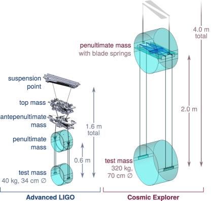

The baseline Cosmic Explorer design assumes scaled-up versions of the quadruple pendulum suspensions used in LIGO [42] and planned for Voyager [12], along with a few modifications, to decrease the seismic and suspension thermal noises. The left panel of Fig. 8 shows a diagram of the LIGO suspensions. Suspension thermal noise is related to the mechanical response of the suspensions through the fluctuation dissipation theorem [43, 44, 45, 46] as , where is the mechanical susceptibility.
In order to minimize thermal noise, the final suspension stage—consisting of the penultimate mass (PUM), the test mass, and the fibers or ribbons between them—is monolithic; for the technology, the material is room-temperature fused silica, and for technology, the material is cryogenic silicon. The top two masses, called the top mass and the antepenultimate mass (APM), are room-temperature maraging steel for both wavelengths. In order to lower the vertical suspension resonances, the top three stages are suspended by steel wires from steel blade springs attached to the stage above.
In order to further reduce the resonances, the test masses are suspended by a final set of blade springs attached to the PUM made from the same material as the PUM and test mass. One concept for the design of this final stage is shown in the right panel of Fig. 8. The stress and spring constant of the blade can be calculated with beam theory [47] by approximating it as a rectangular cantilever of length , width , and thickness . The maximum stress occurs at the clamp, and the spring constant is the ratio of the load suspended by the blade to its maximum deflection at the tip. The blade dimensions should be chosen to minimize while keeping the maximum stress below a safety factor of the breaking stress of the blade.
For the technology, as with LIGO, the silica test mass is suspended from the PUM by four silica fibers welded to the test mass [42]; in Cosmic Explorer they are welded at the top to the blade springs while in LIGO they are welded directly to the PUM. The contribution of the loss angle to the imaginary part of the horizontal spring constant is reduced by the dilution factor , where is the cross-sectional area moment of inertia of the fiber or ribbon [48, 49, 46]. Since for a fiber of radius , it is advantageous to make the radius as small as the breaking stress of the fiber allows. Maximizing the stress in the fiber in this way has the added benefit of reducing the contribution of the fiber to the vertical spring constant and increasing the frequency of the first violin mode, which is proportional to .
The thermoelastic noise of the fiber has two contributions: one from thermal expansion and one from the temperature dependence of the Young modulus. These two contributions cancel when the fiber stress is appropriately chosen. Thus, a tapered fiber is used with a larger radius at the ends (where the most bending, and therefore the most loss, occurs) chosen to give the stress necessary to cancel the thermoelastic noise, and a smaller radius along the length of the fiber chosen to maximize the stress [42].
For the technology, as with Voyager, the silicon test mass is suspended by four silicon ribbons welded to the test mass at the bottom and to the blade springs at the top. Since the ribbons are held near the zero-crossing of the thermal expansion coefficient, the thermoelastic noise in the ribbons cannot be canceled by choice of stress as is done for the fused silica fibers. The ribbon dimensions are therefore chosen to maximize the stress along the entire length of the ribbon. Since for a ribbon of width and thickness , a width-to-thickness ratio of 10:1 is chosen to soften the pendulum in the horizontal direction and to increase the gravitational dilution.
The suspension design also determines the seismic noise, discussed below in Section V.2, since the suspensions provide passive filtering of seismic noise above all of the longitudinal, vertical, and angular resonances. To reduce both seismic and suspension thermal noise, it is thus advantageous to make the suspensions as soft as possible and to lower their resonances.
To achieve this goal, the total allowable height of the suspensions for all technologies has been increased to and the total mass increased to . Within these constraints, in an analysis similar to that done for Voyager [12], the lengths and masses of the silica and silicon suspension stages have been optimized to minimize the sum of these noises over the frequency band of .
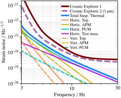
Fig. 9 shows the contributions of each stage to the total suspension thermal noise. The silica suspensions are dominated by the horizontal noise of the PUM and test mass above about with contributions from the horizontal noise of the APM below. The silicon suspensions are dominated by vertical noise of the APM below about , above which the horizontal and vertical noises of the PUM and test mass also start to become important. The addition of blade springs lowers the first vertical mode thus reducing the vertical thermal noises, most importantly from the APM.
The maximum stress that the blade springs, fibers, and ribbons can tolerate is an important material property in the design of the suspensions, and it is difficult to predict what will be possible on a timescale of decades. The maximum stress of the LIGO silica fibers is [42], which provides a safety factor of about six for the breaking stress of fibers realized at the time the LIGO suspensions were designed [50]. Recent improvements to fused silica fiber fabrication suggest that fibers can be made with stresses of , which provides a safety factor of about three [51]. The Cosmic Explorer fused silica suspensions use this for the fibers and tentatively set the maximum blade spring stress to be .
The silicon studies most relevant to the suspensions discussed in this section find that the tensile strength depends on the surface treatment and edge quality, with average breaking stresses measured ranging from and individual samples observed as high as [51, 52]. Cosmic Explorer tentatively sets a maximum stress of for both the blades and ribbons while Voyager uses a more conservative [12]. Nevertheless, larger stresses have been observed in other contexts. Stresses of have been observed in silicon wafers [53] and micro-scale MEMS devices have realized fracture stresses in excess of and stresses of up to have been realized in nano-scale devices [54].
No blade springs have yet been constructed out of either silica or silicon. Developing this technology and techniques for manufacturing highly stressed materials is a critical area of research and development in realizing the low-frequency sensitivity of Cosmic Explorer. Alternatives to blades springs, such as geometric antisprings [55], should also be developed in parallel. Additionally, no experiment on earth has ever directly measured (low) suspension thermal noise.
V.2 Seismic noise
Like Advanced LIGO [57, 42], Cosmic Explorer will suppress seismic noise with passive and active techniques. The suspensions described in Section V.1 passively filter the seismic noise with a slope in amplitude above the suspension resonances, which have been reduced with the optimization described there. Even so, in order to achieve the required seismic noise suppression, the motion of the optical table supporting the suspension will be actively suppressed with a combination of inertial sensors and position sensors. The seismic isolation of the Cosmic Explorer 1 and 2 suspension point is shown in Fig. 10.
For CE1, we assume an isolation performance that is moderately improved compared to Advanced LIGO [57]. At we assume a threefold improvement, and at a tenfold improvement, though to directly increase the seismic isolation the improvement is only needed down to ; seismic isolation improvements below the gravitational-wave band will, however, lessen the requirements on the interferometer control system. The improvement could come, for example, by combining the mechanics of a conventional geophone (GS13) with an interferometric proof mass readout [58]. The noise below is residual ground motion that comes from the inclusion of a position sensor signal to lock the suspension point to the ground on long timescales (also referred to as “blending”). Additionally, the horizontal inertial sensing is susceptible to contamination from ground tilt, and should therefore be paired with low-noise tiltmeters [59]. This is motivated by studies at LIGO Hanford that have shown significant tilt-to-interferometer strain coupling after active seismic isolation [60].333Lowering the tilt coupling, along with mitigating gravity gradient fluctuations from the atmosphere, is an important motivator for carefully designed buildings [61].
For CE2, we assume that improvements in inertial sensing will yield another threefold noise improvement at and a tenfold improvement at , again with the improvement only needed down to to achieve a direct seismic isolation improvement. A variety of designs have been proposed, but common themes include a monolithic proof mass assembly to reduce thermal noise and an optical displacement sensor to reduce readout noise. van Heijningen et al. demonstrated a monolithic accelerometer combined with an interferometric readout that reached a noise floor of above ; this should reach above with continued development [62]. A proposed superconducting niobium upgrade to this system would reduce eddy current damping and greatly improve suspension thermal noise allowing, in principle, above [63]. However, such a device has yet to be demonstrated, and would operate at temperatures below , requiring additional cooling with respect to the Cosmic Explorer cryogenic environment, and would require a low-noise tiltmeter. Development of novel six-dimensional inertial isolators with optical readouts is also progressing [56], and their use with the existing LIGO facilities and Advanced LIGO isolation infrastructure has been explored [64]. These sensors would provide the additional benefit of sensing tilt. Additionally, the improved low-frequency noise of the inertial sensors leads to less reliance on the low-frequency position sensor signal, thereby lessening the contamination from residual ground motion.
V.3 Newtonian noise
Previous studies of Newtonian noise for Cosmic Explorer considered only the contribution from seismic Rayleigh waves, and assumed a Rayleigh-wave noise amplitude equal to that of the existing LIGO facilities [17]. Here we refine that estimate and additionally include the contributions from seismic body waves and from atmospheric infrasound. We start with analytical formulae available in the literature for the infinite half-space, and then additionally we consider numerical simulations that account for trenches that can reduce Newtonian noise relative to the half-space solutions. The Newtonian noise estimates are shown in Fig. 11.
V.3.1 Seismic Newtonian noise
As described in Sec. IV.1, we assume that compared to LIGO, the Cosmic Explorer facility will have a lower Rayleigh-wave noise in the anthropogenic band: above . We also assume a body-wave noise amplitude equal to above , equipartitioned among P-waves, vertically polarized S-waves, and horizontally polarized S-waves.
To compute the Newtonian noise from seismic and infrasonic density fluctuations, we employ the formulae from Harms [31], which are valid for a test mass suspended above a homogeneous, isotropic elastic half-space. We therefore do not consider effect of stratigraphy, other ground anisotropies, the interaction with structures, or the interconversion of different types of seismic waves. These features will need to be accounted for to get a full understanding of the behavior of the local seismic field and hence the Newtonian noise level. For CE1, we have assumed that the effect of seismic Newtonian noise can be mitigated (Section V.3.3) with amplitude suppression of Rayleigh waves. The result in Fig. 11 shows that CE1 is limited by seismic Newtonian noise from –, with a secondary contribution from infrasound. For CE2, we have assumed that seismic Newtonian noise can be further mitigated with amplitude suppression for Rayleigh waves and amplitude suppression for body waves; the result in Fig. 11 shows that CE2 is then limited by atmospheric Newtonian noise, described below.
V.3.2 Atmospheric Newtonian noise
As mentioned in Section IV.2, we assume the Cosmic Explorer facility has a typical infrasound spectrum of ; this is an extrapolation from long-term global infrasound data, available below [36], and assumes no significant contribution from site infrastructure.
To compute the Newtonian noise induced by infrasound fluctuations, we use the calculation in Harms [31], which is valid for a test mass immersed in a fluid half-space. The result is shown in Fig. 11. For both stages of Cosmic Explorer, no suppression is assumed.
As mentioned in Section IV.2, we do not include other processes besides infrasound that produce density fluctuations in the atmosphere, such as advected temperature fluctuations or aeroacoustic noise, because we expect the Newtonian noise induced by these processes to be negligible above a few hertz.
V.3.3 Mitigation strategies
Unlike mechanically coupled seismic and acoustic noise, which can be strongly attenuated by suspending and inertially isolating the test mass inside a vacuum chamber, the Newtonian effect of seismic and acoustic fluctuations cannot be attenuated except by reducing the fluctuation amplitude, increasing the distance from the fluctuations to the test mass, or using auxiliary sensors to estimate the Newtonian contribution to the detector strain channel. Newtonian noise mitigation therefore requires a different set of techniques than for mechanical isolation, and the amount of achievable suppression will not be as great.
CE1 calls for mitigating the seismic Rayleigh-wave Newtonian noise by a factor of in amplitude; CE2 calls for mitigating the seismic Rayleigh-wave Newtonian noise by a factor of in amplitude, and the seismic body-wave Newtonian noise by a factor of 3 in amplitude. This mitigation could be achieved by several means, potentially used in concert:
-
1.
Seismometer array subtraction. Arrays of seismometers can be used to estimate the seismic field in the vicinity of the test mass and thereby subtract Newtonian noise from the gravitational-wave channel [66]. A proof-of-principle experiment to subtract ground motion from a tiltmeter signal achieved a tenfold suppression in the region [60].
-
2.
Excavation underneath the test masses. Nearby density and displacement fluctuations can be suppressed simply by removing earth from the vicinity the test mass, replacing it with a lightweight fill material such as extruded polystyrene if necessary. Harms and Hild [65] computed the suppression of Rayleigh-wave Newtonian noise from a wide and deep hemispherical recess, and here we repeat their analysis to additionally include the effect of the recess on P- and S-waves. The result is shown in Fig. 12, showing that moderate reduction of Rayleigh waves can be achieved near and above , while the reduction of body waves is less significant.
-
3.
Topography and seismic metamaterials. Seismic metamaterials could be built to deflect or dissipate seismic waves before they arrive at the test mass, potentially suppressing surface wave amplitudes by a factor of a few [67, 68, 69, 70, 71, 72]. Similarly, berms, ditches, and other nearby topographic features can affect the propagation of seismic waves, and thus the Newtonian noise level.
No mitigation of infrasound noise is assumed, and thus infrasound is considered a sensitivity limit of the Cosmic Explorer facility. Tropospheric LIDAR, which would otherwise be well-suited to three-dimensional estimation of atmospheric fluctuations, would require sensitivity improvements of several orders of magnitude in order to sense and subtract infrasound [73]. Baffling or otherwise acoustically isolating the interior of the test mass building may be able to reduce the infrasound Newtonian noise below the outdoor value at a discrete set of frequencies [74]. A true cutoff for infrasound noise could be engineered by burying the test mass a depth below ground, which would suppress the noise by , where is the speed of sound; however, to achieve significant suppression for would require . Additionally, underground operation requires a reassessment of the Newtonian noise, since the detector would operate in the bulk of the ground rather than on the surface.
V.4 Test mass thermal noise

Cosmic Explorer will use heavy, high-quality test masses which are turned into high-reflectivity Bragg mirrors by coating the test mass surface with multiple layers of dielectric films. By alternating between high- and low-refractive-index materials, and depositing the layers to a thickness that is the same scale as the laser wavelength, the coating creates the conditions for repeated thin-film interference of the laser beam [75]. The performance of the coating depends on the optical, mechanical, and thermal properties of the materials, which therefore must be chosen with some care [76].
The coating technology will mostly be that of LIGO A+: room-temperature fused silica substrates and coating technology being developed for A+ [77]. Current research aimed at improving the thermal noise of room-temperature coatings holds promise to result in improved coatings for A+ and thus the CE technology [78]. The technology will mostly be that of LIGO Voyager: crystalline silicon substrates operated at , with coating materials that offer improved thermal noise performance over the technology.
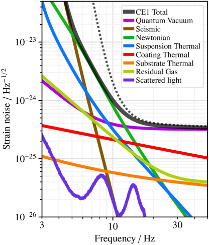
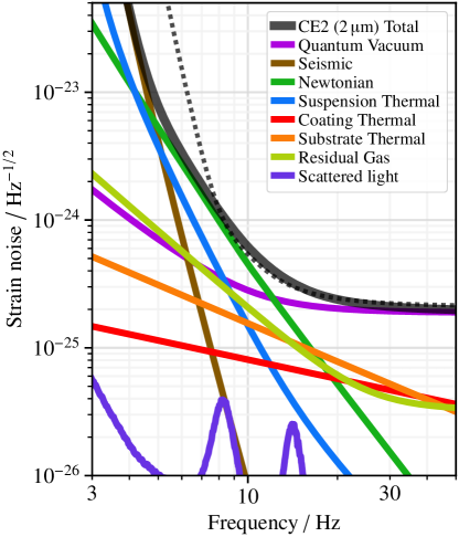
Estimated thermal noises associated with the Cosmic Explorer test masses and their coatings are shown in Fig. 13 and the individual noises are discussed below. Neither the A+ nor the Voyager coating designs have been finalized, so in this work we have made assumptions about the high- and low-index material pairs. Depending on the progression of coating research in the next decade, it is possible that the coatings for CE1 or CE2 may be different from what is presented here, and could potentially use three or more materials to provide more flexibility to simultaneously optimize the optical and thermal noise properties of the mirrors [79, 80].
V.4.1 Substrates
Cosmic Explorer will use test mass substrates; this comes from the desire to make quantum radiation-pressure noise subdominant to other noise sources and the necessity of having large test masses to accommodate the large diameter beams of a nearly diffraction limited long arm cavity. There are several sources of thermal noise in test mass substrates: mechanical (Brownian) noise, thermoelastic noise, and thermorefractive noise.
Brownian fluctuation causes a displacement of the mirror surface with a power spectrum , where is the test mass temperature, is the spot size of the beam, and is the mechanical loss of the substrate material; there are order unity corrections due to the finite size of the test mass and additional loss on the test mass surface [81].
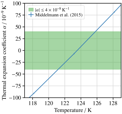
Thermoelastic noise is driven by thermodynamic fluctuations that cause displacement of the test masses via the coefficient of thermal expansion, [82]: the spectrum of the test mass surface displacement due to these fluctuations is , where is the thermal conductivity of the substrate. For fused silica, the contribution of substrate thermoelastic noise to the total instrument noise is negligible. In order to prevent the substrate thermoelastic noise of silicon from making a significant contribution, the substrate temperature must be controlled to near the zero-crossing of the thermal-expansion coefficient [12, 83]. The left panel of Fig. 14 shows that meets the requirement for thermoelastic noise to be an order of magnitude below the total design sensitivity. Based on models [84] and measurements [85] of the temperature dependence of , this constraint on translates to a temperature control requirement of relative to the zero-crossing temperature of . This temperature control accuracy is also sufficient to keep thermoelastic noise of the silicon components of the suspension from contributing significantly to the total low frequency suspension thermal noise for the technology as shown in Fig. 9.

| Quantity | Technology | Technology | Remarks | ||
|---|---|---|---|---|---|
| Substrate | Material | Fused silica | Crystalline silicon | ||
| Temperature | To within for CE2 | ||||
| Diameter | |||||
| Thickness | |||||
| Mass | |||||
| Thermal expansion coeff. | See remark on | ||||
| Refractive index | |||||
| Thermorefractive coeff. | |||||
| Thermal conductivity | |||||
| Coating | Materials | SiO2 / TBD | SiO2 / aSi | Low index / high index | |
| Refractive indices | 1.45 / 2.07 | 1.44 / 3.5 | |||
| Loss angles | / | / | |||
| ITM coating layers | |||||
| ETM coating layers | |||||
| Optical | Vacuum wavelength | ||||
| ITM spot size | intensity radius | ||||
| ETM spot size | |||||
| ITM transmissivity | |||||
| ETM transmissivity | |||||
To achieve temperature control, it may be sufficient to control the test mass temperatures to a fixed value (for example using the frequency of the internal modes of the silicon test masses as a reference for temperature), or it may be necessary to determine the set temperature based on minimizing the observed noise or by actively measuring the substrates’ values. The sign change of around the zero crossing allows for a signed error-signal that would enable negative feedback control. Typical room temperature variations achieved at the current LIGO observatories are of order , and even better accuracy should be achievable with feedback control [86, 83]. Temperature gradients due to heating from the environment and from absorbed laser power also need to be considered. If a power is absorbed on some area of the test mass and dissipates into the substrate, the resulting temperature variation is determined by Fourier’s law, which reads approximately , where is a relevant length dimension for the test mass (both the thickness and diameter are of similar magnitude for Cosmic Explorer). This suggests that in the case of a few watts of laser power absorbed in the coating (i.e., a coating absorption of roughly ), the temperature variation in the substrate should be of order tens of millikelvins, which is within the limit set by the thermoelastic noise coupling.
The same thermal fluctuations that drive thermoelastic noise also cause phase fluctuations in light passing through the substrates, which is relevant for the two input test masses (ITMs). For both silica and cryogenic silicon, this phase fluctuation is dominated by changes in the index of refraction via the thermorefractive coefficient [87, 88, 89]. The power spectrum of this noise is , where is the thickness of the test mass, and is the finesse of the arm cavities, and is the transmissivity of the input test masses. For fused silica, this noise is well below the other test mass thermal noises. For cryogenic silicon, the higher thermal conductivity and larger thermorefractive coefficient make this noise non-negligible; with the choice of , the thermorefractive noise at dominates the total test mass thermal noise for the technology,444The finesse could be increased to decrease the thermorefractive noise and the power absorbed in the input test mass substrates; however, this value is chosen as a compromise to reduce the effects of signal extraction cavity loss on the high frequency quantum noise, which favors small . and is similar in magnitude to the coating Brownian thermal noise at for the technology.
Additionally, the semiconductor nature of silicon gives rise to refractive index fluctuations due to the motion of free carriers in the silicon test masses. Initial estimates of this noise source [90] suggested that the phase noise induced by these fluctuations could be significant, but a more recent analysis that includes Debye screening indicates that this noise will lie several orders of magnitude below the total thermal noise of the substrate [91]. We therefore do not consider this noise source.
Finally, we remark on the static birefringence effects in the test mass substrates. Cosmic Explorer, like current gravitational-wave laser interferometers, is designed to operate in a single linear polarization; interconversion of polarization inside the interferometer acts as an optical loss. The greatest potential for polarization interconversion is in the substrates of the input test masses, and consequently the optical gain of the power-recycling cavity could be impacted. Given a mass thickness of and a birefringence , the power-recycling gain is limited to [92]; maintaining therefore requires . This already appears achievable in existing fused-silica interferometers, and in laboratory measurements of monocrystalline silicon [93]; for the large-diameter masses of Cosmic Explorer, particularly for the silicon technology which has not yet been demonstrated for kilometer-scale instruments, small birefringence must be maintained over a large area, requiring good optical isotropy and control of the stresses in the substrate.
V.4.2 Coating noises
As with the test mass substrates, the thin-film coatings applied to the test masses also exhibit thermal noises that are driven by mechanical and thermodynamic fluctuations.
The technology assumes the same target set for the LIGO A+ coatings: an effective factor of 4 overall reduction in mechanical loss compared to the current Advanced LIGO coatings. This will likely be achieved using silica for the low-index layers, and a yet-to-be-determined metal oxide (or set of metal oxides) for the high-index layers. Recent measurements indicate that the loss angle of thin-film silica can be as low as [77]; to reach the loss reduction target, this requires a loss angle of the high-index layers of . The technology assumes LIGO Voyager coatings, where the low-refractive-index layer is again SiO2, but the high-refractive-index is now amorphous silicon (aSi) with at most optical absorption [12].
The coating Brownian noise is computed using the formalism of Hong et al. [94], with the photoelastic effect ignored and the loss angle in bulk and shear strains assumed to be equal.555A formula for Brownian noise under these assumptions is given by Eq. 1 of Yam et al. [79], but the expression for their coefficient has an error; the corrected expression using their notation is [80]
As in the substrates, thermodynamic fluctuations produce phase fluctuations of the light propagating in the coatings. The phase fluctuations are mediated by the coating’s average coefficients of thermal expansion and thermorefraction . Because of the etalon effect, these coefficients act with opposite sign, leading to an overall thermo-optic effect that for most coatings—including the Cosmic Explorer coatings—is smaller than the thermoelastic or thermorefractive effects individually [95].
V.5 Quantum noise
The quantum vacuum fluctuations of the modes of the electromagnetic field that enter the antisymmetric port of the interferometer are a significant source of noise at all frequencies [96, 97, 98]. Quantum radiation pressure noise is caused by the laser light in the arm cavities beating with the vacuum fluctuations in the amplitude quadrature of these modes, producing a fluctuating radiation pressure force acting on the test masses. Shot noise is caused by the beating of the laser with the vacuum fluctuations in the orthogonal phase quadrature, which carries the gravitational wave strain signal.
It is possible to alter the correlations between the fluctuations in these two quadratures in order to modify the quantum radiation pressure and shot noises. This is a rich subject which we do not attempt to review here; see, for example, Refs. [99, 100, 101] and references therein. We summarize only those aspects strictly relevant to the Cosmic Explorer design outlined in Section III. Radiation pressure dominates at low frequencies with a strain power spectral density . Shot noise dominates at higher frequencies; within the bandwidth of the instrument, the strain power spectral density of the shot noise is , where is the power in the arm cavities and is the mass of the test masses. The crossover occurs at a frequency of about for Cosmic Explorer. The technologies have arm powers of , respectively, so both realizations of CE2 have the same level of quantum noise.
Squeezed vacuum states [102, 103] can be injected into the antisymmetric port to reduce the noise in one quadrature at the expense of increasing the noise in the orthogonal quadrature, a technique which is being used in Advanced LIGO [104] and Advanced Virgo [105]. Therefore, this necessitates a tradeoff between reducing radiation pressure at low frequencies and shot noise at high frequencies. However, the frequency dependence necessary to achieve a broadband noise reduction can be realized by first reflecting the squeezed vacuum off of a detuned optical cavity, known as a filter cavity, before injection into the interferometer [97, 106, 107]. The production of these frequency dependent squeezed vacuum states has been realized experimentally [108, 109] and will be used in LIGO A+ and Advanced Virgo+.
Cosmic Explorer will employ a long filter cavity to achieve a broadband quantum noise reduction of for CE1 and for both realizations of CE2. The filter cavity is critical in achieving the low frequency goals: without it and with this level of squeezing at mid to high frequencies, CE1 would be limited by radiation pressure down to and CE2 would be limited down to .
V.6 Residual gas noise
The residual gas in the vacuum system is responsible for two noise sources. The first is a phase noise caused by fluctuations of the gas column density in the beam tubes. The contribution to this noise from a particular molecular species with partial pressure in the tube, mass , and polarizability is white up to a cutoff frequency , determined by the time it takes for a molecule to cross the laser beam, with a power spectrum , where is the temperature of the tube, is the wavelength, is the laser beam’s waist, is the length of the arm, and is the thermal velocity of the molecule. [38, 39].
The second is a force noise caused by the residual gas in the chambers exerting a damping force on the test masses. The contribution of one molecular species with partial pressure in a chamber to this noise has a power spectrum , where and are the mass and radius of the test mass, respectively, and is the temperature of the chamber [40, 41]. The magnitude of these two noise sources determine the pressure requirements in the beam tubes and test mass chambers for each gas species described in Section IV.3.
V.7 Scattered light noise


Scattering of light within the beam tubes is a source of noise for all ground-based interferometric gravitational wave detectors, as first calculated by Thorne [110]. Imperfections on the surface of the test masses lead to scattering of the main cavity mode, which can be broadly grouped into two classes:
-
•
surface roughness, which are variations on the test mass surface responsible mostly for scattering at narrow angles; and
-
•
point defects, which are “bright spots” on the mirror’s surface that produce diffuse scattering and are therefore responsible mostly for scattering at wide angles.
These imperfections on the test masses cause light to scatter out of the cavity and reflect multiple times off the beam tube wall as it propagates down the tube, and eventually recombine with the main cavity mode at the opposite test mass. Seismic motion of the beam tube imposes a phase noise on the scattered light each time it reflects off the tube, and gives rise to readout noise when the light recombines. Scattering of this nature was first pointed out by Thorne as an important noise source for the LIGO beam tubes (see Section III.B. of [110]). To address this, baffles were installed at various points along the LIGO beam tubes to deflect scattered light away from the test masses. However, the baffles give rise to back-scattering noise, whereby light that is scattered out of the cavity by one of the test masses is back-scattered off one of the baffles and subsequently recombines with the main cavity mode at the same test mass. Motion of the beam tube then imposes a phase noise on the back-scattered light, which gives rise to readout noise when the light recombines. A detailed explanation of this effect is given by Flanagan and Thorne [111] and a detailed analysis of back-scattering specifically for Cosmic Explorer is given in a recent technical report [112], which we summarize below. The effect of forward scattering, meaning the diffraction of the main beam whose time dependence arises primarily from seismically induced transverse motion of the baffles, is left for future work [113, 114]. Additionally, the phase information of the baffle surfaces is not considered in this work, though simulations on Advanced LIGO indicate that the inclusion of this information can cause the scatter-induced strain noise power spectral density to fluctuate by an order of magnitude in either direction [115].
The fractional power scattered per unit solid angle is quantified by the bidirectional reflectance distribution function (BRDF), and the power spectrum of noise due to back scattered light is , where is the BRDF of the backscattering surface (i.e., the baffles and beam tube) and is related to the square of the mirror BRDF. Furthermore, is the longitudinal displacement noise of the beam tube, taking into account fringe-wrapping as explained in [116] and Section 3.1 of [112]. Here we use beam tube motion measured from the LIGO Livingston observatory, but the Cosmic Explorer baffles can be suspended to reduce their motion if necessary. Cosmic Explorer will likely use baffles with a black nickel coating with a BRDF of [117], however diamond-like carbon coatings with a BRDF of can be used if necessary.
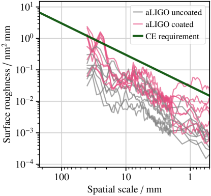
Surface roughness of spatial frequency gives rise to scattering at angle , where is the optical wavelength, and is measured relative to the beam tube axis. The BRDF for this small angle scattering due to surface roughness is proportional to the PSD of the mirror surface variations at spatial frequency . The left panel of Fig. 16 shows the noise due to surface scattering using the surface PSD shown in Fig. 15, assuming a tube diameter and baffle aperture diameter. This PSD, with functional form , is an upper limit requirement on the surface roughness over an appropriate range of spatial scales that scatter into the tube, based on Sec. 2.2 of [112], which results in noise due to surface scattering that is at least a factor of ten below the design sensitivity at all frequencies. This requirement is comparable to the surface roughness that has already been achieved with the Advanced LIGO test masses at spatial scales below a few centimeters. (Comparison is harder at larger spatial scales, where the Advanced LIGO surface roughness is not well characterized.)
Point defects give rise to diffuse scattering, which has a roughly constant BRDF. The right panel of Fig. 16 shows the scattered light noise due to point defects assuming a mirror BRDF of , and a tube diameter. It appears that diffuse scattering is an insignificant noise source for all phases of Cosmic Explorer.
The choice of beam tube diameter is of particular importance for the design of Cosmic Explorer. While wider tubes lead to less scattering noise, they are also substantially more expensive considering the cost of the vacuum envelope, the metal needed for the tube, and the market availability of various tube dimensions. Fig. 16 shows that a diameter tube is sufficient to keep the back-scattering noise below the noise requirements for both phases of the interferometer, provided that the requirements on mirror surface roughness are met. This limit on beam tube size will be reevaluated once the effects of forward scattering are considered.
V.8 Noise associated with controls
As a practical matter, the relative distances between the suspended optics as well as their angular alignment must be precisely servo controlled in order to keep the interferometer stable and operating in the linear regime. Noise from the sensors used to measure the linear and angular degrees of freedom is imposed on the optics by the control systems needed to suppress their relative positions and orientations.
In addition to the differential arm motion of the four test masses, there are three auxiliary length degrees of freedom of the other core optics, which are suspended from triple pendulum suspensions, that must be controlled. These degrees of freedom are limited by seismic noise below a few hertz and by sensing noise (of similar magnitude to that of Advanced LIGO) at higher frequencies. The auxiliary degree of freedom with the strongest coupling to the differential arm motion is the Michelson degree of freedom: differential motion between the beamsplitter and the input test masses also produce phase fluctuations at the anti-symmetric port. The Michelson degree of freedom is suppressed by a factor of relative to the differential arm motion since the latter is enhanced by the Fabry-Pérot arm cavities. The Michelson sensing noise is of order [118], which gives an equivalent strain sensitivity of . Simulations show that if this motion is sensed and subtracted from the differential arm motion, a control loop with a bandwidth of a few hertz is sufficient to suppress the Michelson noise to within a factor of 10 below the design sensitivities for both CE1 and CE2. Simulations also suggest that the couplings of the other two auxiliary length degrees of freedom, fluctuations in the power recycling and signal extraction cavity lengths, do not significantly couple to the differential arm motion through the fundamental optical mode.
The noise from the angular control systems is one of the most challenging low frequency technical noise sources in current gravitational wave detectors, and it is also expected to be so for third generation detectors. Radiation pressure from the circulating arm power exerts a torque on the mirrors. This torque stiffens (or hardens) the torsional resonance when the cavity mirrors rotate with the same sign, and softens the resonance when the mirrors rotate with opposite sign [119, 120, 121, 122]. The hard and soft resonances are shifted by , where is the moment of inertia of the mirrors, is a geometric factor for the hard mode, and is a geometric factor for the soft mode. The soft mode will become unstable if the torque is large enough and the (negative) shift exceeds the mechanical resonance . In this case, the bandwidth of the angular control loop needs to be several times the frequency of this unstable mode in order to stabilize the optomechanical system. Achieving this requirement without injecting excess sensing noise is challenging.
It is thus clearly advantageous to prevent the soft mode from becoming unstable. In this case the control loop bandwidth needs to be [12]. One way to achieve this is to reduce the frequency shift . The arm power and length are set and the geometric factor is constrained by the necessity of minimizing the beam spot sizes. However, the moment of inertia can be increased, perhaps by increasing the test mass thickness or altering the geometry in some other way. Another possibility is to increase the free torsional resonance . The soft mode frequency shifts are approximately for the technology and for the technology. The soft mode will thus be stable, necessitating a sufficiently low loop bandwidth of a few hertz, if .
Even though the frequency shift for the hard mode is always positive and the hard mode always stable, it can still be excited and must be damped. Two factors make this requirement intrinsically easier for Cosmic Explorer than for Advanced LIGO. First, the typical amplitude of these excitations will be less due to the improved seismic isolation. Second, the geometric factor for the hard mode is, to first order, proportional to where and are the beam radii at the waist and at an optic, respectively [119]. The ratio needs to be small for CE to reduce diffraction over , while for Advanced LIGO it is made large to reduce coating thermal noise. This results in hard mode frequency shifts of approximately for the technology and for the technology.
We have only sketched the requirements for the control system and its noise performance here; while these preliminary considerations suggest that it will be possible to meet the low frequency requirements, a realistic understanding of the control noise is a significant source of uncertainty facing Cosmic Explorer and warrants a more detailed analysis.
VI Discussion and Conclusion
| Activity | Theme | Fac. | CE1 | CE2(1) | CE2(2) | |
| Partial pressures of gases (IV.3) | Vacuum | |||||
| Ambient seismic field characterization, incl. surface and body wave content (IV.1) | Seismic arrays | |||||
| Ambient infrasound field characterization, distinguished from wind-induced sensor noise (IV.2) | Infrasonic arrays | |||||
| Reduction of seismic field near test masses (V.3.3) | Seismic metamaterials | |||||
| Reduction of magnetic field coupling | Other environmental | |||||
| horiz. susp. point motion at (V.2) | Inertial sensing | |||||
| 2 subtraction of surface-wave NN (V.3.1) | Seismic arrays | |||||
| arm power and FD squeezing (silica) | QN, scatter | |||||
| Silica test mass, ; low impurity | Silica materials science | |||||
| Highly stressed silica blade springs (V.1) | Silica materials science | |||||
| Validation of silica loss mechanisms at | Silica materials science | |||||
| A+ coatings over (V.4.2) | Thin-film mirror coatings | |||||
| Test mass surface polishing of large substrates (V.7) | Mirror metrology | |||||
| Control noise | Optical sensing and control | |||||
| 10 subtraction of surface-wave NN (V.3.1) | Seismic arrays | |||||
| 3 subtraction of body-wave NN (V.3.1) | Seismic arrays | |||||
| Best effort at mitigation of infrasonic NN | Infrasonic arrays | |||||
| horiz. susp. point motion at (V.2) | Inertial sensing | |||||
| arm power and FD squeezing (silica) | QN, scatter | |||||
| Silicon test mass, ; low impurity | Silicon materials science | |||||
| Highly stressed silicon blade springs and ribbons (V.1) | Silicon materials science | |||||
| Validation of silicon loss mechanims at | Silicon materials science | |||||
| “Voyager” coatings over (V.4.2) | Thin-film mirror coatings | |||||
| arm power and FD squeezing (silicon) | QN, scatter | |||||
| Radiative temperature control to (V.4.1) | Cryogenics |
In this work we have presented updated sensitivity curves for Cosmic Explorer and have also identified several areas of research and development that will be necessary to realize its low-frequency performance.
-
•
the identification of a facility site with low seismic and acoustic noise, and other suitable environmental properties;
-
•
the development of low-noise inertial isolators in multiple degrees of freedom;
-
•
the continued development of mitigation techniques for Newtonian noise;
-
•
the production of large, high-quality test mass substrates, both silica and silicon;
-
•
the polishing and coating of large test mass substrates to a resulting spatial roughness comparable to that achieved for the Advanced LIGO test masses, but characterized at larger spatial scales;
-
•
the development of suitable mirror coatings;
-
•
the development of long multi-stage suspensions employing highly stressed silica and silicon blade springs and silica fibers and silicon ribbons to support test masses;
-
•
the development of alternatives to blade spring suspensions, such as geometric anti-springs;
-
•
the validation and extension of the beam-tube scattering model presented here;
-
•
the development of a robust angular control system with possible modifications to the suspensions and/or test masses to reduce the effects of radiation pressure instabilities;
-
•
the development of vacuum technology and practice capable of achieving ultra-high vacuum in both the test mass chambers, which will be periodically vented, and the beam tubes;
-
•
the measurement of material properties, such as mechanical loss angles, down to ; and
-
•
the development of laser frequency and intensity noise requirements and the optical topologies required to achieve them not discussed here.
Table 3 summarizes the research required to reach the low frequency sensitivity presented here along with a rough timeline of when that research would need to be completed.
We have also shown that both the and technologies can realize nearly identical low frequency sensitivities for CE2. While this is true for high frequencies as well, achieving the specified quantum and thermal noise performance for both technologies requires further research and development not discussed in this paper. Additionally, if the arm length of Cosmic Explorer were significantly shortened, the relative importance of the various noise sources may change since they scale differently with arm length [17].
Acknowledgements.
The authors gratefully acknowledge the support of the National Science Foundation through collaborative award numbers 1836814, 1836809, 1836734, and 1836702. EDH is supported by the MathWorks, Inc. JRS is partially supported by the Dan Black Family Trust. BK is supported by the Heising-Simons Foundation. This work has document numbers CE–P2000005 and LIGO–P2000405.Appendix A Summary of Cosmic Explorer Technologies

One advantage of realizing Cosmic Explorer incrementally is that CE1 can achieve significantly higher sensitivities than the second generation detectors mostly using the existing technology developed for LIGO A+. In addition to providing a relatively short route to increased sensitivity, this provides some risk management: significant improvements can still be made even if some advanced technologies are not realized. Nevertheless, the baseline CE1 design does rely on some technological advances beyond A+. We can also consider a more conservative detector, CE1, which relies solely on A+ technology with the improved sensitivity coming only from scaling up the arm length, test masses, and suspensions from the A+ design. In particular, this would differ from CE1 by the following:
-
•
No fused silica blade springs on the final suspension stage between the PUM and the test mass. The suspensions are just a scaled up version of the A+ suspensions.
-
•
No Newtonian Rayleigh wave suppression.
-
•
The same level of suspension point motion as A+, a factor of 10 worse than CE1 at .
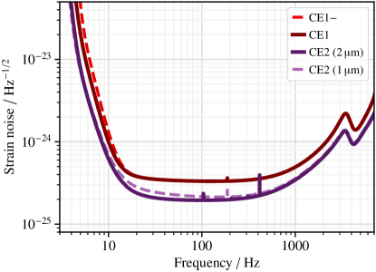
Fig. 17 shows the low-frequency limit to the spectral sensitivity of CE1. These changes only affect the low-frequency noise below about leaving identical high-frequency sensitivities for CE1 and CE1. This can also be thought of as an initial detector to be implemented first while some of the above technologies are being developed for CE1 if necessary.
A summary of the defining parameters of the different Cosmic Explorer detectors and technologies is given in Table 4 and their sensitivities compared in Fig. 18; many of the other details common to all detectors using the same technology are given in Table 2. All of the detectors share the same basic properties: arm power, material, temperature, coatings, and beam spot sizes. The low-frequency sensitivity of CE1 is improved over CE1 by the addition of fused silica blades springs, which reduce the suspension thermal and seismic noises as described in Sections V.1 and V.2; improved seismic isolation, as discussed in Section V.2; and some suppression of Newtonian Rayleigh waves, as discussed in Section V.3. The test mass thermal noises, most importantly coating Brownian, are the same for all detectors using technology since they use the same test mass substrates and coatings, beam sizes, and temperatures.
| Quantity | Units | CE1 | CE1 | CE2 () | CE2 () |
|---|---|---|---|---|---|
| Arm power | |||||
| Wavelength | |||||
| Squeezing | |||||
| Material | Silica | Silica | Silica | Silicon | |
| Temperature | |||||
| Final stage blade | No | Yes | Yes | Yes | |
| Rayleigh wave suppr. | None | ||||
| Body wave suppr. | None | None | |||
| Susp. point at | |||||
| Coatings | A+ | A+ | A+ | Voyager | |
| ITM spot size | |||||
| ETM spot size |
The high frequency sensitivity of CE2 is nearly identical for both the and technologies since this is determined by quantum shot noise. The realization of CE2 has the same squeezing as the realization— increased from for CE1. Since the shot noise scales as , the factor of two larger power stored in the arms of the realization gives the same shot noise level as the realization. All other technologies not dependent on test mass material or laser wavelength are the same for both realizations of CE2. In particular, the seismic isolation is improved over that of CE1 by a factor of 10 at , Newtonian body waves are suppressed by a factor of three, and Newtonian Rayleigh waves are suppressed by an additional factor of five over that of CE1. Both realizations thus have the same Newtonian noise.
To summarize, the low frequency sensitivity is dominated by suspension thermal, seismic, and Newtonian noise. The low frequency sensitivity of CE1 is improved over that of CE1 due to improved suspensions, seismic isolation, and the addition of Newtonian noise suppression. The low frequency sensitivity of CE2 is improved over that of CE1 through further improvements to the seismic isolation and Newtonian noise suppression and increased squeezing. Since the high frequency sensitivity is determined by quantum shot noise, CE1 and CE1 have the same high frequency sensitivity, as do both realizations of CE2.
Appendix B Displacement and Force Sensitivity


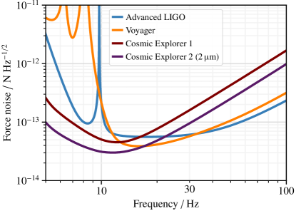
Fig. 19 compares the noise of Cosmic Explorer, Advanced LIGO, and Voyager in terms of gravitational wave strain and the equivalent test mass displacement and force noises. To achieve its design sensitivity above , Cosmic Explorer does not require as low displacement or force noise as does Voyager, owing to the longer arms and larger test masses. However, significant improvements in displacement and force noises are required to achieve the Cosmic Explorer strain sensitivity at lower frequencies.
References
- LIGO Scientific Collaboration et al. [2015] LIGO Scientific Collaboration, J. Aasi, B. P. Abbott, R. Abbott, T. Abbott, M. R. Abernathy, K. Ackley, C. Adams, T. Adams, P. Addesso, and et al., Classical and Quantum Gravity 32, 074001 (2015), arXiv:1411.4547 [gr-qc] .
- Acernese et al. [2015] F. Acernese, M. Agathos, K. Agatsuma, D. Aisa, N. Allemandou, A. Allocca, J. Amarni, P. Astone, G. Balestri, G. Ballardin, and et al., Classical and Quantum Gravity 32, 024001 (2015), arXiv:1408.3978 [gr-qc] .
- Kagra Collaboration et al. [2019] Kagra Collaboration, T. Akutsu, M. Ando, K. Arai, Y. Arai, S. Araki, A. Araya, N. Aritomi, H. Asada, Y. Aso, S. Atsuta, K. Awai, S. Bae, L. Baiotti, M. A. Barton, K. Cannon, E. Capocasa, C. S. Chen, T. W. Chiu, K. Cho, Y. K. Chu, K. Craig, W. Creus, K. Doi, K. Eda, Y. Enomoto, R. Flaminio, Y. Fujii, M. K. Fujimoto, M. Fukunaga, M. Fukushima, T. Furuhata, S. Haino, K. Hasegawa, K. Hashino, K. Hayama, S. Hirobayashi, E. Hirose, B. H. Hsieh, C. Z. Huang, B. Ikenoue, Y. Inoue, K. Ioka, Y. Itoh, K. Izumi, T. Kaji, T. Kajita, M. Kakizaki, M. Kamiizumi, S. Kanbara, N. Kanda, S. Kanemura, M. Kaneyama, G. Kang, J. Kasuya, Y. Kataoka, N. Kawai, S. Kawamura, T. Kawasaki, C. Kim, J. Kim, J. C. Kim, W. S. Kim, Y. M. Kim, N. Kimura, T. Kinugawa, S. Kirii, Y. Kitaoka, H. Kitazawa, Y. Kojima, K. Kokeyama, K. Komori, A. K. H. Kong, K. Kotake, R. Kozu, R. Kumar, H. S. Kuo, S. Kuroyanagi, H. K. Lee, H. M. Lee, H. W. Lee, M. Leonardi, C. Y. Lin, F. L. Lin, G. C. Liu, Y. Liu, E. Majorana, S. Mano, M. Marchio, T. Matsui, F. Matsushima, Y. Michimura, N. Mio, O. Miyakawa, A. Miyamoto, T. Miyamoto, K. Miyo, S. Miyoki, W. Morii, S. Morisaki, Y. Moriwaki, T. Morozumi, M. Musha, K. Nagano, S. Nagano, K. Nakamura, T. Nakamura, H. Nakano, M. Nakano, K. Nakao, T. Narikawa, L. Naticchioni, L. Nguyen Quynh, W. T. Ni, A. Nishizawa, Y. Obuchi, T. Ochi, J. J. Oh, S. H. Oh, M. Ohashi, N. Ohishi, M. Ohkawa, K. Okutomi, K. Ono, K. Oohara, C. P. Ooi, S. S. Pan, J. Park, F. E. Peña Arellano, I. Pinto, N. Sago, M. Saijo, S. Saitou, Y. Saito, K. Sakai, Y. Sakai, Y. Sakai, M. Sasai, M. Sasaki, Y. Sasaki, S. Sato, N. Sato, T. Sato, Y. Sekiguchi, N. Seto, M. Shibata, T. Shimoda, H. Shinkai, T. Shishido, A. Shoda, K. Somiya, E. J. Son, A. Suemasa, T. Suzuki, T. Suzuki, H. Tagoshi, H. Tahara, H. Takahashi, R. Takahashi, A. Takamori, H. Takeda, H. Tanaka, K. Tanaka, T. Tanaka, S. Tanioka, E. N. Tapia San Martin, D. Tatsumi, T. Tomaru, T. Tomura, F. Travasso, K. Tsubono, S. Tsuchida, N. Uchikata, T. Uchiyama, T. Uehara, S. Ueki, K. Ueno, F. Uraguchi, T. Ushiba, M. H. P. M. van Putten, H. Vocca, S. Wada, T. Wakamatsu, Y. Watanabe, W. R. Xu, T. Yamada, A. Yamamoto, K. Yamamoto, K. Yamamoto, S. Yamamoto, T. Yamamoto, K. Yokogawa, J. Yokoyama, T. Yokozawa, T. H. Yoon, T. Yoshioka, H. Yuzurihara, S. Zeidler, and Z. H. Zhu, Nature Astronomy 3, 35 (2019), arXiv:1811.08079 [gr-qc] .
- Abbott et al. [2016a] B. P. Abbott, R. Abbott, T. D. Abbott, M. R. Abernathy, F. Acernese, K. Ackley, C. Adams, T. Adams, P. Addesso, R. X. Adhikari, and et al., Phys. Rev. Lett. 116, 061102 (2016a), arXiv:1602.03837 [gr-qc] .
- Abbott et al. [2016b] B. P. Abbott, R. Abbott, T. D. Abbott, M. R. Abernathy, F. Acernese, K. Ackley, C. Adams, T. Adams, P. Addesso, R. X. Adhikari, and et al., Physical Review X 6, 041015 (2016b), arXiv:1606.04856 [gr-qc] .
- Abbott et al. [2017a] B. P. Abbott, R. Abbott, T. D. Abbott, F. Acernese, K. Ackley, C. Adams, T. Adams, P. Addesso, R. X. Adhikari, V. B. Adya, and et al., Phys. Rev. Lett. 119, 161101 (2017a), arXiv:1710.05832 [gr-qc] .
- Abbott et al. [2017b] B. P. Abbott, R. Abbott, T. D. Abbott, F. Acernese, K. Ackley, C. Adams, T. Adams, P. Addesso, R. X. Adhikari, V. B. Adya, and et al., ApJ 848, L12 (2017b), arXiv:1710.05833 [astro-ph.HE] .
- Abbott et al. [2019a] B. P. Abbott, R. Abbott, T. D. Abbott, S. Abraham, F. Acernese, K. Ackley, C. Adams, R. X. Adhikari, V. B. Adya, C. Affeldt, and et al., Physical Review X 9, 031040 (2019a), arXiv:1811.12907 [astro-ph.HE] .
- Nitz et al. [2019] A. H. Nitz, C. Capano, A. B. Nielsen, S. Reyes, R. White, D. A. Brown, and B. Krishnan, Astrophys. J. 872, 195 (2019), arXiv:1811.01921 [gr-qc] .
- Abbott et al. [2019b] B. P. Abbott, R. Abbott, T. D. Abbott, S. Abraham, F. Acernese, K. Ackley, C. Adams, R. X. Adhikari, V. B. Adya, C. Affeldt, and et al., Astrophys. J. 875, 161 (2019b), arXiv:1901.03310 [astro-ph.HE] .
- Miller et al. [2015] J. Miller, L. Barsotti, S. Vitale, P. Fritschel, M. Evans, and D. Sigg, Phys. Rev. D 91, 062005 (2015), arXiv:1410.5882 [gr-qc] .
- Adhikari et al. [2020] R. X. Adhikari, K. Arai, A. F. Brooks, C. Wipf, O. Aguiar, P. Altin, B. Barr, L. Barsotti, R. Bassiri, A. Bell, G. Billingsley, R. Birney, D. Blair, E. Bonilla, J. Briggs, D. D. Brown, R. Byer, H. Cao, M. Constancio, S. Cooper, T. Corbitt, D. Coyne, A. Cumming, E. Daw, R. deRosa, G. Eddolls, J. Eichholz, M. Evans, M. Fejer, E. C. Ferreira, A. Freise, V. V. Frolov, S. Gras, A. Green, H. Grote, E. Gustafson, E. D. Hall, G. Hammond, J. Harms, G. Harry, K. Haughian, D. Heinert, M. Heintze, F. Hellman, J. Hennig, M. Hennig, S. Hild, J. Hough, W. Johnson, B. Kamai, D. Kapasi, K. Komori, D. Koptsov, M. Korobko, W. Z. Korth, K. Kuns, B. Lantz, S. Leavey, F. Magana-Sandoval, G. Mansell, A. Markosyan, A. Markowitz, I. Martin, R. Martin, D. Martynov, D. E. McClelland, G. McGhee, T. McRae, J. Mills, V. Mitrofanov, M. Molina-Ruiz, C. Mow-Lowry, J. Munch, P. Murray, S. Ng, M. A. Okada, D. J. Ottaway, L. Prokhorov, V. Quetschke, S. Reid, D. Reitze, J. Richardson, R. Robie, I. Romero-Shaw, R. Route, S. Rowan, R. Schnabel, M. Schneewind, F. Seifert, D. Shaddock, B. Shapiro, D. Shoemaker, A. S. Silva, B. Slagmolen, J. Smith, N. Smith, J. Steinlechner, K. Strain, D. Taira, S. Tait, D. Tanner, Z. Tornasi, C. Torrie, M. Van Veggel, J. Vanheijningen, P. Veitch, A. Wade, G. Wallace, R. Ward, R. Weiss, P. Wessels, B. Willke, H. Yamamoto, M. J. Yap, and C. Zhao, Classical and Quantum Gravity 37, 165003 (2020), arXiv:2001.11173 [astro-ph.IM] .
- Ackley et al. [2020] K. Ackley, V. B. Adya, P. Agrawal, P. Altin, G. Ashton, M. Bailes, E. Baltinas, A. Barbuio, D. Beniwal, C. Blair, D. Blair, G. N. Bolingbroke, V. Bossilkov, S. Shachar Boublil, D. D. Brown, B. J. Burridge, J. Calderon Bustillo, J. Cameron, H. Tuong Cao, J. B. Carlin, S. Chang, P. Charlton, C. Chatterjee, D. Chattopadhyay, X. Chen, J. Chi, J. Chow, Q. Chu, A. Ciobanu, T. Clarke, P. Clearwater, J. Cooke, D. Coward, H. Crisp, R. J. Dattatri, A. T. Deller, D. A. Dobie, L. Dunn, P. J. Easter, J. Eichholz, R. Evans, C. Flynn, G. Foran, P. Forsyth, Y. Gai, S. Galaudage, D. K. Galloway, B. Gendre, B. Goncharov, S. Goode, D. Gozzard, B. Grace, A. W. Graham, A. Heger, F. Hernandez Vivanco, R. Hirai, N. A. Holland, Z. J. Holmes, E. Howard, E. Howell, G. Howitt, M. T. Hübner, J. Hurley, C. Ingram, V. Jaberian Hamedan, K. Jenner, L. Ju, D. P. Kapasi, T. Kaur, N. Kijbunchoo, M. Kovalam, R. Kumar Choudhary, P. D. Lasky, M. Y. M. Lau, J. Leung, J. Liu, K. Loh, A. Mailvagan, I. Mandel, J. J. McCann, D. E. McClelland, K. McKenzie, D. McManus, T. McRae, A. Melatos, P. Meyers, H. Middleton, M. T. Miles, M. Millhouse, Y. Lun Mong, B. Mueller, J. Munch, J. Musiov, S. Muusse, R. S. Nathan, Y. Naveh, C. Neijssel, B. Neil, S. W. S. Ng, V. Oloworaran, D. J. Ottaway, M. Page, J. Pan, M. Pathak, E. Payne, J. Powell, J. Pritchard, E. Puckridge, A. Raidani, V. Rallabhandi, D. Reardon, J. A. Riley, L. Roberts, I. M. Romero-Shaw, T. J. Roocke, G. Rowell, N. Sahu, N. Sarin, L. Sarre, H. Sattari, M. Schiworski, S. M. Scott, R. Sengar, D. Shaddock, R. Shannon, J. SHI, P. Sibley, B. J. J. Slagmolen, T. Slaven-Blair, R. J. E. Smith, J. Spollard, L. Steed, L. Strang, H. Sun, A. Sunderland, S. Suvorova, C. Talbot, E. Thrane, D. Töyrä, P. Trahanas, A. Vajpeyi, J. V. van Heijningen, A. F. Vargas, P. J. Veitch, A. Vigna-Gomez, A. Wade, K. Walker, Z. Wang, R. L. Ward, K. Ward, S. Webb, L. Wen, K. Wette, R. Wilcox, J. Winterflood, C. Wolf, B. Wu, M. Jet Yap, Z. You, H. Yu, J. Zhang, J. Zhang, C. Zhao, and X. Zhu, PASA 37, e047 (2020), arXiv:2007.03128 [astro-ph.HE] .
- The GWIC 3G Science Case Team Consortium [2019] The GWIC 3G Science Case Team Consortium, The Next-Generation Global Gravitational-Wave Observatory: New Astrophysics with the Farthest, Oldest, and Most Violent Events in the Universe, Tech. Rep. (GWIC, 2019).
- GWIC, GWIC-3G, GWIC-3G-R&D-Consortium [2019] GWIC, GWIC-3G, GWIC-3G-R&D-Consortium, 3G R&D: Research and Development for the Next Generation of Ground-based Gravitational-wave Detectors, Tech. Rep. (GWIC, 2019).
- Hild et al. [2011] S. Hild, M. Abernathy, F. Acernese, P. Amaro-Seoane, N. Andersson, K. Arun, F. Barone, B. Barr, M. Barsuglia, M. Beker, N. Beveridge, S. Birindelli, S. Bose, L. Bosi, S. Braccini, C. Bradaschia, T. Bulik, E. Calloni, G. Cella, E. Chassande Mottin, S. Chelkowski, A. Chincarini, J. Clark, E. Coccia, C. Colacino, J. Colas, A. Cumming, L. Cunningham, E. Cuoco, S. Danilishin, K. Danzmann, R. De Salvo, T. Dent, R. De Rosa, L. Di Fiore, A. Di Virgilio, M. Doets, V. Fafone, P. Falferi, R. Flaminio, J. Franc, F. Frasconi, A. Freise, D. Friedrich, P. Fulda, J. Gair, G. Gemme, E. Genin, A. Gennai, A. Giazotto, K. Glampedakis, C. Gräf, M. Granata, H. Grote, G. Guidi, A. Gurkovsky, G. Hammond, M. Hannam, J. Harms, D. Heinert, M. Hendry, I. Heng, E. Hennes, J. Hough, S. Husa, S. Huttner, G. Jones, F. Khalili, K. Kokeyama, K. Kokkotas, B. Krishnan, T. G. F. Li, M. Lorenzini, H. Lück, E. Majorana, I. Mandel, V. Mandic, M. Mantovani, I. Martin, C. Michel, Y. Minenkov, N. Morgado, S. Mosca, B. Mours, H. Müller-Ebhardt, P. Murray, R. Nawrodt, J. Nelson, R. Oshaughnessy, C. D. Ott, C. Palomba, A. Paoli, G. Parguez, A. Pasqualetti, R. Passaquieti, D. Passuello, L. Pinard, W. Plastino, R. Poggiani, P. Popolizio, M. Prato, M. Punturo, P. Puppo, D. Rabeling, P. Rapagnani, J. Read, T. Regimbau, H. Rehbein, S. Reid, F. Ricci, F. Richard, A. Rocchi, S. Rowan, A. Rüdiger, L. Santamaría, B. Sassolas, B. Sathyaprakash, R. Schnabel, C. Schwarz, P. Seidel, A. Sintes, K. Somiya, F. Speirits, K. Strain, S. Strigin, P. Sutton, S. Tarabrin, A. Thüring, J. van den Brand, M. van Veggel, C. van den Broeck, A. Vecchio, J. Veitch, F. Vetrano, A. Vicere, S. Vyatchanin, B. Willke, G. Woan, and K. Yamamoto, Classical and Quantum Gravity 28, 094013 (2011), arXiv:1012.0908 [gr-qc] .
- Abbott et al. [2017c] B. P. Abbott, R. Abbott, T. D. Abbott, M. R. Abernathy, K. Ackley, C. Adams, P. Addesso, R. X. Adhikari, V. B. Adya, C. Affeldt, and et al., Classical and Quantum Gravity 34, 044001 (2017c), arXiv:1607.08697 [astro-ph.IM] .
- Reitze et al. [2019a] D. Reitze, LIGO Laboratory: California Institute of Technology, LIGO Laboratory: Massachusetts Institute of Technology, LIGO Hanford Observatory, and LIGO Livingston Observatory, BAAS 51, 141 (2019a), arXiv:1903.04615 [astro-ph.IM] .
- Reitze et al. [2019b] D. Reitze, R. X. Adhikari, S. Ballmer, B. Barish, L. Barsotti, G. Billingsley, D. A. Brown, Y. Chen, D. Coyne, R. Eisenstein, M. Evans, P. Fritschel, E. D. Hall, A. Lazzarini, G. Lovelace, J. Read, B. S. Sathyaprakash, D. Shoemaker, J. Smith, C. Torrie, S. Vitale, R. Weiss, C. Wipf, and M. Zucker, in Bulletin of the American Astronomical Society, Vol. 51 (2019) p. 35, arXiv:1907.04833 [astro-ph.IM] .
- The LIGO Scientific Collaboration et al. [2020] The LIGO Scientific Collaboration, the Virgo Collaboration, R. Abbott, T. D. Abbott, S. Abraham, F. Acernese, K. Ackley, A. Adams, C. Adams, R. X. Adhikari, and et al., arXiv e-prints , arXiv:2010.14533 (2020), arXiv:2010.14533 [astro-ph.HE] .
- Wainstein and Zubakov [1970] L. A. Wainstein and V. D. Zubakov, Extraction of Signals from Noise (1970).
- Finn and Chernoff [1993] L. S. Finn and D. F. Chernoff, Phys. Rev. D 47, 2198 (1993), arXiv:gr-qc/9301003 [gr-qc] .
- Creighton and Anderson [2011] J. Creighton and W. Anderson, Gravitational-Wave Physics and Astronomy: An Introduction to Theory, Experiment and Data Analysis. (2011).
- Cutler and Flanagan [1994] C. Cutler and É. E. Flanagan, Phys. Rev. D 49, 2658 (1994), arXiv:gr-qc/9402014 [gr-qc] .
- Sesana et al. [2009] A. Sesana, J. Gair, I. Mandel, and A. Vecchio, ApJ 698, L129 (2009), arXiv:0903.4177 [astro-ph.CO] .
- Chen et al. [2021] H.-Y. Chen, D. E. Holz, J. Miller, M. Evans, S. Vitale, and J. Creighton, Classical and Quantum Gravity 38, 055010 (2021), arXiv:1709.08079 [astro-ph.CO] .
- Marković [1993] D. Marković, Phys. Rev. D 48, 4738 (1993).
- Izumi and Sigg [2017] K. Izumi and D. Sigg, Classical and Quantum Gravity 34, 015001 (2017).
- Amann et al. [2020] F. Amann, F. Bonsignorio, T. Bulik, H. J. Bulten, S. Cuccuru, A. Dassargues, R. DeSalvo, E. Fenyvesi, F. Fidecaro, I. Fiori, C. Giunchi, A. Grado, J. Harms, S. Koley, L. Kovács, G. Losurdo, V. Mandic, P. Meyers, L. Naticchioni, F. Nguyen, G. Oggiano, M. Olivieri, F. Paoletti, A. Paoli, W. Plastino, M. Razzano, P. Ruggi, G. Saccorotti, A. M. Sintes, L. Somlai, P. Ván, and M. Vasúth, Review of Scientific Instruments 91, 094504 (2020), arXiv:2003.03434 [physics.ins-det] .
- Peterson [1993] J. R. Peterson, Observations and modeling of seismic background noise, Tech. Rep. (US Geological Survey, 1993).
- Harms [2019] J. Harms, Living Reviews in Relativity 22, 6 (2019).
- Meltzer et al. [1999] A. Meltzer, R. Rudnick, P. Zeitler, A. Levander, G. Humphreys, K. Karlstrom, E. Ekstrom, C. Carlson, T. Dixon, M. Gurnis, et al., Geological Society of America TODAY 9, 8 (1999).
- Benz et al. [2001] H. Benz, R. Buland, J. Filson, A. Frankel, and K. Shedlock, Seismological Research Letters 72, 70 (2001).
- Nguyen et al. [2021] P. Nguyen, R. M. S. Schofield, A. Effler, C. Austin, V. Adya, M. Ball, S. Banagiri, K. Banowetz, C. Billman, C. D. Blair, and et al., arXiv e-prints , arXiv:2101.09935 (2021), arXiv:2101.09935 [astro-ph.IM] .
- Bonnefoy-Claudet et al. [2006] S. Bonnefoy-Claudet, F. Cotton, and P.-Y. Bard, Earth-Science Reviews 79, 205 (2006).
- Bowman et al. [2005] J. R. Bowman, G. E. Baker, and M. Bahavar, Geophys. Res. Lett. 32, L09803 (2005).
- Creighton [2008] T. Creighton, Classical and Quantum Gravity 25, 125011 (2008), arXiv:gr-qc/0007050 [gr-qc] .
- Zucker and Whitcomb [1996] M. E. Zucker and S. E. Whitcomb, in Proceedings of the Seventh Marcel Grossman Meeting on recent developments in theoretical and experimental general relativity, gravitation, and relativistic field theories, edited by R. T. Jantzen, G. Mac Keiser, and R. Ruffini (1996) p. 1434.
- Takahashi et al. [2002] R. Takahashi, Y. Saito, M. Fukushima, M. Ando, K. Arai, D. Tatsumi, G. Heinzel, S. Kawamura, T. Yamazaki, and S. Moriwaki, Journal of Vacuum Science Technology 20, 1237 (2002).
- Cavalleri et al. [2010] A. Cavalleri, G. Ciani, R. Dolesi, M. Hueller, D. Nicolodi, D. Tombolato, S. Vitale, P. J. Wass, and W. J. Weber, Physics Letters A 374, 3365 (2010), arXiv:0907.5375 [physics.class-ph] .
- Dolesi et al. [2011] R. Dolesi, M. Hueller, D. Nicolodi, D. Tombolato, S. Vitale, P. J. Wass, W. J. Weber, M. Evans, P. Fritschel, R. Weiss, J. H. Gundlach, C. A. Hagedorn, S. Schlamminger, G. Ciani, and A. Cavalleri, Phys. Rev. D 84, 063007 (2011), arXiv:1108.3254 [gr-qc] .
- Aston et al. [2012] S. M. Aston, M. A. Barton, A. S. Bell, N. Beveridge, B. Bland, A. J. Brummitt, G. Cagnoli, C. A. Cantley, L. Carbone, A. V. Cumming, L. Cunningham, R. M. Cutler, R. J. S. Greenhalgh, G. D. Hammond, K. Haughian, T. M. Hayler, A. Heptonstall, J. Heefner, D. Hoyland, J. Hough, R. Jones, J. S. Kissel, R. Kumar, N. A. Lockerbie, D. Lodhia, I. W. Martin, P. G. Murray, J. O’Dell, M. V. Plissi, S. Reid, J. Romie, N. A. Robertson, S. Rowan, B. Shapiro, C. C. Speake, K. A. Strain, K. V. Tokmakov, C. Torrie, A. A. van Veggel, A. Vecchio, and I. Wilmut, Classical and Quantum Gravity 29, 235004 (2012).
- Callen and Welton [1951] H. B. Callen and T. A. Welton, Physical Review 83, 34 (1951).
- Callen and Greene [1952] H. B. Callen and R. F. Greene, Physical Review 86, 702 (1952).
- González and Saulson [1994] G. I. González and P. R. Saulson, Acoustical Society of America Journal 96, 207 (1994).
- González [2000] G. González, Classical and Quantum Gravity 17, 4409 (2000), arXiv:gr-qc/0006053 [gr-qc] .
- Gere and Timoshenko [1997] J. M. Gere and S. P. Timoshenko, Mechanics of Materials, 4th ed. (PWS Publishing Company, 1997).
- Saulson [1990] P. R. Saulson, Phys. Rev. D 42, 2437 (1990).
- Gretarsson et al. [2000] A. M. Gretarsson, G. M. Harry, S. D. Penn, P. R. Saulson, W. J. Startin, S. Rowan, G. Cagnoli, and J. Hough, Physics Letters A 270, 108 (2000), arXiv:gr-qc/9912057 [gr-qc] .
- Tokmakov et al. [2012] K. V. Tokmakov, A. Cumming, J. Hough, R. Jones, R. Kumar, S. Reid, S. Rowan, N. A. Lockerbie, A. Wanner, and G. Hammond, Journal of Non Crystalline Solids 358, 1699 (2012).
- Lee et al. [2019] K.-H. Lee, G. Hammond, J. Hough, R. Jones, S. Rowan, and A. Cumming, Classical and Quantum Gravity 36, 185018 (2019).
- Cumming et al. [2014] A. V. Cumming, L. Cunningham, G. D. Hammond, K. Haughian, J. Hough, S. Kroker, I. W. Martin, R. Nawrodt, S. Rowan, C. Schwarz, and A. A. van Veggel, Classical and Quantum Gravity 31, 025017 (2014).
- McLaughlin and Willoughby [1987] J. C. McLaughlin and A. F. W. Willoughby, Journal of Crystal Growth 85, 83 (1987).
- DelRio et al. [2015] F. W. DelRio, R. F. Cook, and B. L. Boyce, Applied Physics Reviews 2, 021303 (2015).
- Cella et al. [2002] G. Cella, R. DeSalvo, V. Sannibale, H. Tariq, N. Viboud, and A. Takamori, Nuclear Instruments and Methods in Physics Research A 487, 652 (2002).
- Mow-Lowry and Martynov [2019] C. M. Mow-Lowry and D. Martynov, Classical and Quantum Gravity 36, 245006 (2019), arXiv:1801.01468 [astro-ph.IM] .
- Matichard et al. [2015] F. Matichard, B. Lantz, R. Mittleman, K. Mason, J. Kissel, B. Abbott, S. Biscans, J. McIver, R. Abbott, S. Abbott, E. Allwine, S. Barnum, J. Birch, C. Celerier, D. Clark, D. Coyne, D. DeBra, R. DeRosa, M. Evans, S. Foley, P. Fritschel, J. A. Giaime, C. Gray, G. Grabeel, J. Hanson, C. Hardham, M. Hillard, W. Hua, C. Kucharczyk, M. Landry, A. Le Roux, V. Lhuillier, D. Macleod, M. Macinnis, R. Mitchell, B. O’Reilly, D. Ottaway, H. Paris, A. Pele, M. Puma, H. Radkins, C. Ramet, M. Robinson, L. Ruet, P. Sarin, D. Shoemaker, A. Stein, J. Thomas, M. Vargas, K. Venkateswara, J. Warner, and S. Wen, Classical and Quantum Gravity 32, 185003 (2015), arXiv:1502.06300 [physics.ins-det] .
- Cooper et al. [2018] S. J. Cooper, C. J. Collins, A. C. Green, D. Hoyland, C. C. Speake, A. Freise, and C. M. Mow-Lowry, Classical and Quantum Gravity 35, 095007 (2018), arXiv:1710.05943 [astro-ph.IM] .
- Venkateswara et al. [2014] K. Venkateswara, C. A. Hagedorn, M. D. Turner, T. Arp, and J. H. Gundlach, Review of Scientific Instruments 85, 015005 (2014), arXiv:1401.4412 [physics.ins-det] .
- Coughlin et al. [2018] M. W. Coughlin, J. Harms, J. Driggers, D. J. McManus, N. Mukund, M. P. Ross, B. J. J. Slagmolen, and K. Venkateswara, Phys. Rev. Lett. 121, 221104 (2018), arXiv:1807.07427 [astro-ph.IM] .
- Ross et al. [2020] M. P. Ross, K. Venkateswara, C. Mow-Lowry, S. Cooper, J. Warner, B. Lantz, J. Kissel, H. Radkins, T. Shaffer, R. Mittleman, A. Pele, and J. Gundlach, Classical and Quantum Gravity 37, 185018 (2020), arXiv:2003.06447 [physics.ins-det] .
- van Heijningen et al. [2018] J. V. van Heijningen, A. Bertolini, and J. F. J. van den Brand, in 2018 IEEE Sensors Applications Symposium (SAS) (2018) pp. 1–5.
- van Heijningen [2020] J. V. van Heijningen, Journal of Instrumentation 15 (6), P06034, arXiv:1909.12956 [physics.app-ph] .
- Yu et al. [2018] H. Yu, D. Martynov, S. Vitale, M. Evans, D. Shoemaker, B. Barr, G. Hammond, S. Hild, J. Hough, S. Huttner, S. Rowan, B. Sorazu, L. Carbone, A. Freise, C. Mow-Lowry, K. L. Dooley, P. Fulda, H. Grote, and D. Sigg, Phys. Rev. Lett. 120, 141102 (2018), arXiv:1712.05417 [astro-ph.IM] .
- Harms and Hild [2014] J. Harms and S. Hild, Classical and Quantum Gravity 31, 185011 (2014), arXiv:1406.2253 [gr-qc] .
- Driggers et al. [2012] J. C. Driggers, J. Harms, and R. X. Adhikari, Phys. Rev. D 86, 102001 (2012), arXiv:1207.0275 [gr-qc] .
- Brûlé et al. [2014] S. Brûlé, E. H. Javelaud, S. Enoch, and S. Guenneau, Phys. Rev. Lett. 112, 133901 (2014).
- Colombi et al. [2016] A. Colombi, D. Colquitt, P. Roux, S. Guenneau, and R. V. Craster, Scientific Reports 6, 27717 (2016).
- Palermo et al. [2016] A. Palermo, S. Krödel, A. Marzani, and C. Daraio, Scientific Reports 6, 39356 (2016).
- Roux et al. [2018] P. Roux, D. Bindi, T. Boxberger, A. Colombi, F. Cotton, I. Douste-Bacque, S. Garambois, P. Gueguen, G. Hillers, D. Hollis, et al., Seismological Research Letters 89, 582 (2018).
- Kamai and LIGO Team [2019] B. Kamai and LIGO Team, in APS April Meeting Abstracts, APS Meeting Abstracts, Vol. 2019 (2019) p. R11.006.
- Zaccherini et al. [2020] R. Zaccherini, A. Colombi, A. Palermo, V. K. Dertimanis, A. Marzani, H. R. Thomsen, B. Stojadinovic, and E. N. Chatzi, Physical Review Applied 13, 034055 (2020), arXiv:1912.00617 [physics.geo-ph] .
- Fiorucci [2019] D. Fiorucci, in GWADW 2019 (Elba, 2019).
- Fiorucci et al. [2018] D. Fiorucci, J. Harms, M. Barsuglia, I. Fiori, and F. Paoletti, Phys. Rev. D 97, 062003 (2018), arXiv:1801.04564 [astro-ph.IM] .
- Fowles [1968] G. R. Fowles, Introduction to Modern Optics (1968).
- Harry et al. [2012] G. Harry, T. P. Bodiya, and R. DeSalvo, Optical Coatings and Thermal Noise in Precision Measurement (2012).
- Granata et al. [2020] M. Granata, A. Amato, G. Cagnoli, M. Coulon, J. Degallaix, D. Forest, L. Mereni, C. Michel, L. Pinard, B. Sassolas, and J. Teillon, Appl. Opt. 59, A229 (2020), arXiv:1912.11394 [physics.ins-det] .
- Vajente et al. [2020] G. Vajente, M. Fazio, L. Yang, A. Ananyeva, G. Billingsley, A. Markosyan, R. Bassiri, M. Fejer, and C. Menoni, Bulletin of the American Physical Society (2020).
- Yam et al. [2015] W. Yam, S. Gras, and M. Evans, Phys. Rev. D 91, 042002 (2015), arXiv:1411.3234 [physics.optics] .
- Tait et al. [2020] S. C. Tait, J. Steinlechner, M. M. Kinley-Hanlon, P. G. Murray, J. Hough, G. McGhee, F. Pein, S. Rowan, R. Schnabel, C. Smith, L. Terkowski, and I. W. Martin, Phys. Rev. Lett. 125, 011102 (2020).
- Gras and Evans [2018] S. Gras and M. Evans, Phys. Rev. D 98, 122001 (2018), arXiv:1802.05372 [physics.ins-det] .
- Braginsky et al. [1999] V. B. Braginsky, M. L. Gorodetsky, and S. P. Vyatchanin, Physics Letters A 264, 1 (1999), arXiv:cond-mat/9912139 [cond-mat.mtrl-sci] .
- Aaron Markowitz [2018] Aaron Markowitz, Cryogenic Cooling for LIGO Voyager, Tech. Rep. LIGO-G1801047-v3 (LIGO Laboratory, Caltech, 2018) GWADW 2018.
- Kim et al. [2018] D. S. Kim, O. Hellman, J. Herriman, H. L. Smith, J. Y. Y. Lin, N. Shulumba, J. L. Niedziela, C. W. Li, D. L. Abernathy, and B. Fultz, Proceedings of the National Academy of Science 115, 1992 (2018), arXiv:1610.08737 [cond-mat.mtrl-sci] .
- Middelmann et al. [2015] T. Middelmann, A. Walkov, G. Bartl, and R. Schödel, Phys. Rev. B 92, 174113 (2015), arXiv:1507.06822 [cond-mat.mtrl-sci] .
- Mandy Cheung and Aaron Markowitz and Brittany Kamai and Rana X. Adhikari [2018] Mandy Cheung and Aaron Markowitz and Brittany Kamai and Rana X. Adhikari, Real-Time Temperature Monitoring of Mechanical Oscillators, Tech. Rep. LIGO-T1800312-v2 (LIGO Laboratory, 2018) SURF18 project.
- Braginsky et al. [2000] V. B. Braginsky, M. L. Gorodetsky, and S. P. Vyatchanin, Physics Letters A 271, 303 (2000), arXiv:cond-mat/0008109 [cond-mat.mtrl-sci] .
- Heinert et al. [2011] D. Heinert, A. G. Gurkovsky, R. Nawrodt, S. P. Vyatchanin, and K. Yamamoto, Phys. Rev. D 84, 062001 (2011).
- Braginsky and Vyatchanin [2004] V. B. Braginsky and S. P. Vyatchanin, Physics Letters A 324, 345 (2004), arXiv:cond-mat/0402650 [cond-mat.stat-mech] .
- Heinert et al. [2014] D. Heinert, A. Bell, G. Cagnoli, J. Degallaix, G. Gemme, S. Hild, J. Hough, H. Lück, , I. W. Martin, S. Rowan, S. P. Vyatchanin, and R. Nawrodt, Free carrier driven noise in transmissive semiconductor optics, Tech. Rep. LIGO–P1400084–v1 (LIGO, 2014).
- Bruns et al. [2020] F. Bruns, S. P. Vyatchanin, J. Dickmann, R.Glaser, D.Heinert, R.Nawrodt, and S. Kroker, Thermal charge carrier driven noise in transmissive semiconductor optics, Tech. Rep. LIGO–P2000048–v1 (LIGO, 2020).
- Winkler et al. [1994] W. Winkler, A. Rüdiger, R. Schilling, K. A. Strain, and K. Danzmann, Optics Communications 112, 245 (1994).
- Krüger et al. [2016] C. Krüger, D. Heinert, A. Khalaidovski, J. Steinlechner, R. Nawrodt, R. Schnabel, and H. Lück, Classical and Quantum Gravity 33, 015012 (2016), arXiv:1504.06503 [physics.optics] .
- Hong et al. [2013] T. Hong, H. Yang, E. K. Gustafson, R. X. Adhikari, and Y. Chen, Phys. Rev. D 87, 082001 (2013), arXiv:1207.6145 [gr-qc] .
- Evans et al. [2008] M. Evans, S. Ballmer, M. Fejer, P. Fritschel, G. Harry, and G. Ogin, Phys. Rev. D 78, 102003 (2008), arXiv:0807.4774 [gr-qc] .
- Caves [1981] C. M. Caves, Phys. Rev. D 23, 1693 (1981).
- Kimble et al. [2002] H. J. Kimble, Y. Levin, A. B. Matsko, K. S. Thorne, and S. P. Vyatchanin, Phys. Rev. D 65, 022002 (2002), arXiv:gr-qc/0008026 [gr-qc] .
- Buonanno and Chen [2002] A. Buonanno and Y. Chen, Phys. Rev. D 65, 042001 (2002), arXiv:gr-qc/0107021 [gr-qc] .
- Danilishin and Khalili [2012] S. L. Danilishin and F. Y. Khalili, Living Reviews in Relativity 15, 5 (2012), arXiv:1203.1706 [quant-ph] .
- Hild [2014] S. Hild, A Basic Introduction to Quantum Noise and Quantum-Non-Demolition Techniques, in Advanced Interferometers and the Search for Gravitational Waves, Vol. 404, edited by M. Bassan (2014) p. 291.
- Miao and Chen [2012] H. Miao and Y. Chen, Quantum theory of laser interferometer gravitational wave detectors, in Advanced Gravitational Wave Detectors, edited by D. G. Blair, E. J. Howell, L. Ju, and C. Zhao (Cambridge University Press, 2012) p. 277–297.
- Schnabel [2017] R. Schnabel, Phys. Rep. 684, 1 (2017), arXiv:1611.03986 [quant-ph] .
- Barsotti et al. [2019] L. Barsotti, J. Harms, and R. Schnabel, Reports on Progress in Physics 82, 016905 (2019).
- Tse et al. [2019] M. Tse, H. Yu, N. Kijbunchoo, A. Fernandez-Galiana, P. Dupej, L. Barsotti, C. D. Blair, D. D. Brown, S. E. Dwyer, A. Effler, and et al., Phys. Rev. Lett. 123, 231107 (2019).
- Acernese et al. [2019] F. Acernese, M. Agathos, L. Aiello, A. Allocca, A. Amato, S. Ansoldi, S. Antier, M. Arène, N. Arnaud, S. Ascenzi, and et al., Phys. Rev. Lett. 123, 231108 (2019).
- Evans et al. [2013] M. Evans, L. Barsotti, P. Kwee, J. Harms, and H. Miao, Phys. Rev. D 88, 022002 (2013), arXiv:1305.1599 [physics.optics] .
- Kwee et al. [2014] P. Kwee, J. Miller, T. Isogai, L. Barsotti, and M. Evans, Phys. Rev. D 90, 062006 (2014), arXiv:1704.03531 [physics.optics] .
- Oelker et al. [2016] E. Oelker, T. Isogai, J. Miller, M. Tse, L. Barsotti, N. Mavalvala, and M. Evans, Phys. Rev. Lett. 116, 041102 (2016).
- McCuller et al. [2020] L. McCuller, C. Whittle, D. Ganapathy, K. Komori, M. Tse, A. Fernandez-Galiana, L. Barsotti, P. Fritschel, M. MacInnis, F. Matichard, K. Mason, N. Mavalvala, R. Mittleman, H. Yu, M. E. Zucker, and M. Evans, Phys. Rev. Lett. 124, 171102 (2020), arXiv:2003.13443 [astro-ph.IM] .
- Thorne [1981] K. Thorne, Light Scattering and Proposed Baffle Configuration for the LIGO, Tech. Rep. LIGO-T890017-00-R (LIGO, 1981).
- Flanagan and Thorne [1994] E. Flanagan and K. Thorne, Noise Due to Backscatter Off Baffles, the Nearby Wall, and Objects at the Far end of the Beam Tube, and Recommended Actions, Tech. Rep. LIGO-T940063-00-R (LIGO, 1994).
- Bai [2019] Y. Bai, Cosmic Explorer: Back-scatter Noise and Design Recommendations, Tech. Rep. LIGO-T1900854-v1 (LIGO, 2019).
- Éanna É. Flanagan and Thorne [1995] Éanna É. Flanagan and K. Thorne, Light Scattering and Baffle Configuration for LIGO, Tech. Rep. T950101 (LIGO, 1995).
- Nourrit et al. [2001] V. Nourrit, J. L. de Bougrenet de La Tocnaye, and P. Chanclou, Journal of the Optical Society of America A 18, 546 (2001).
- Day [2013] R. Day, FFT Simulation using FOG, Tech. Rep. G1300532 (LIGO, 2013).
- Ottaway et al. [2012] D. J. Ottaway, P. Fritschel, and S. J. Waldman, Optics Express 20, 8329 (2012).
- Ananyeva [2019] A. Ananyeva, BRDF vs R^2 of Black Ni and DLC coatings sampes on super#8 SSTL, Tech. Rep. LIGO-T1700450 (LIGO, 2019).
- Martynov et al. [2016] D. V. Martynov, E. D. Hall, B. P. Abbott, R. Abbott, T. D. Abbott, C. Adams, R. X. Adhikari, R. A. Anderson, S. B. Anderson, K. Arai, and et al., Phys. Rev. D 93, 112004 (2016), arXiv:1604.00439 [astro-ph.IM] .
- Sidles and Sigg [2006] J. A. Sidles and D. Sigg, Physics Letters A 354, 167 (2006).
- Barsotti et al. [2010] L. Barsotti, M. Evans, and P. Fritschel, Classical and Quantum Gravity 27, 084026 (2010).
- Hirose et al. [2010] E. Hirose, K. Kawabe, D. Sigg, R. Adhikari, and P. R. Saulson, Appl. Opt. 49, 3474 (2010), arXiv:0909.0010 [gr-qc] .
- Dooley et al. [2013] K. L. Dooley, L. Barsotti, R. X. Adhikari, M. Evans, T. T. Fricke, P. Fritschel, V. Frolov, K. Kawabe, and N. Smith-Lefebvre, Journal of the Optical Society of America A 30, 2618 (2013), arXiv:1310.3662 [physics.ins-det] .