Exploiting Implicit Kinematic Kernel for Controlling a Wearable Robotic Extra-finger
Abstract
In the last decades, wearable robots have been proposed as technological aids for rehabilitation, assistance, and functional substitution for patients suffering from motor disorders and impairments. Robotic extra-limbs and extra-fingers are representative examples of the technological and scientific achievements in this field. However, successful and intuitive strategies to control and cooperate with the aforementioned wearable aids are still not well established.
Against this background, this work introduces an innovative control strategy based on the exploitation of the residual motor capacity of impaired limbs. We aim at helping subjects with a limited mobility and/or physical impairments to control wearable extra-fingers in a natural, comfortable, and intuitive way. The novel idea here presented lies on taking advantage of the redundancy of the human kinematic chain involved in a task to control an extra degree of actuation (DoA). This concept is summarized in the definition of the Implicit Kinematic Kernel (IKK). As first investigation, we developed a procedure for the real time analysis of the body posture and the consequent computation of the IKK-based control signal in the case of single-arm tasks. We considered both bio-mechanical and physiological human features and constraints to allow for an efficient and intuitive control approach. Towards a complete evaluation of the proposed control system, we studied the users’ capability of exploiting the Implicit Kinematic Kernel both in virtual and real environments, asking subjects to track different reference signals and to control a robotic extra-finger to accomplish pick-and-place tasks. Obtained results demonstrated that the proposed approach is suitable for controlling a wearable robotic extra-finger in a user-friendly way.
Index Terms:
Wearable Robots, Wearable interfaces, Human Performance Augmentation.I Introduction
Wearable robotic devices offer the possibility to augment human capabilities in terms of perception, resources, and force, with a design that is especially thought to fit the human body. When adopted as technological aids for assistance and rehabilitation purposes, ease of use and ease of learning become crucial to foster device acceptance. Such ease should be recognizable under several aspects, ranging from the intuitiveness of the system control strategy to the user’s autonomy while using the technology. Enhancing autonomy in patients suffering from motor disorders and impairments is fundamental to improve their quality of life. To this aim, it is important to increase the user-device synergy and, thus, minimize as much as possible the intervention of external operators. The research done in the last decades in healthcare-oriented wearable robotics has led to the development of several devices. By considering the ultimate aim of a device as its discerning characteristic, wearable devices can be broadly grouped in three main categories.
The first category includes all the wearable technologies proposed as substitute for a missing part of the body, as a limb. Generally, they are referred to as prosthesis and they have to comply with critical design guidelines [1]. Prosthesis control is usually based on neural or electromyographic (EMG) signals [2, 3] and, depending on the adopted strategy, it can be more or less invasive [4]. The major goal of such devices is to achieve prosthesis embodiment, so as to experience the artificial limb as truly incorporated into the body schema.
The second category consists of devices designed to strengthen the human body in order to deal with either lost or impaired functionalities. Orthosis and exoskeletons belong to this category [5], as well as a wide range of assistive devices that spans from supernumerary robotic limbs [6] and fingers [7] to robotic arms controlled by wearable interfaces [8]. Depending on whether the targeted functionality can be restored or not, two different approaches can be carried out. Either the device is designed to restore the impaired capability, or to compensate the lost functionality by augmenting the human body. Although these devices are not intrinsic part of the body, an appropriate human-robot interface is crucial to allow the system to be perceived as a real extension of the user. Thus, it is fundamental to develop functional and user-based control techniques in order to encourage the patient to take advantage of a technology rather than perceiving it as a source of frustration.
The last category includes devices developed for training or rehabilitation purposes. In this case, the focus is not only on the achievement of an effective treatment [9], but also on the stimulation of the patient’s active participation. Indeed, to encourage motor learning it is preferable to have systems that collaborate with the user rather than override the user’s behaviour [10].
As a result of this analysis, it is possible to outline two different control strategies. From the user’s viewpoint, they can be distinguished as non-autonomous and autonomous. Here, the term non-autonomous will be used to mean an intentional and dedicated control which requires precise instructions from the user. As an example, the patient can activate an extra-finger through a push button placed on a ring worn on the healthy hand [11]. On the contrary, the term autonomous will be used to describe a control law which is able to adapt the system functioning to the user’s will without receiving explicit commands. This is usually represented by a control signal associated to an action which is not clearly distinguishable from those required by the target task. For instance, an exoskeleton supporting the wearer’s gait should follow the intention of walking without waiting for specific instructions on when to make a step.
As this paper aims at introducing a novel approach to non-autonomous control, we overview the state of the art focusing on such techniques adopted to control wearable robotics devices. In [12], Noritsugu et al. proposed a wearable power assist device for hand grasping that can be activated thanks to an expiration switch. Differently, Takahashi et al. [13] controlled the functions of the Hand-Wrist Assisting Robotic Device (HWARD) through a customized software interface. This 3-DoF pneumatically-actuated robotic device assists grasping and releasing movements leaving the palmar surface of the hand unobstructed. In [14], Hasegawa et al. developed a wearable handling support system for human hand, wrist joint, and elbow joint. The exoskeleton control law is based on the wearer’s head motion: two 3-axis accelerometers are installed on a cap in order to detect pitch, roll, and yaw motions, so that the user can control the support system by tilting or rotating his/her head. At a later time, In et al. introduced the Exo-Glove [15], a soft wearable hand robot that uses a soft tendon routing system and an underactuation adaptive mechanism. In order to exploit the tenodesis effect, i.e. a phenomenon for which a passive finger flexion occurs in response to wrist extension, the input command for the control is the wrist motion. In [16], Prattichizzo et al. presented for the first time the Sixth Finger, a modular extra-finger that can be worn on the wrist. While the mechanical design of the prototype has remained quite similar, several control strategies have been exploited in the last five years. As a first approach, a dataglove was used to capture the motion of the human hand, which was mapped in the motion of the extra-finger. In [17] and [18] the device flexion/extension was regulated through a wearable switch embedded in a ring, while in [19] surface electrodes placed on the user’s frontalis muscle allowed to capture an EMG signal to activate the device motion.
In this context, the goal of this research is to introduce a new control paradigm which is highly focused on users and their tasks. In particular, this research addresses people suffering from physical impairments and motor disorders. The underlying idea is to exploit the redundancy of the human kinematic chain to control wearable devices. To understand the potentiality of this approach, the wide range of movements that can be performed to complete the same task must be considered. This redundancy is not surprising considering the complexity of the human body: Zatsiorsky in [20] estimated that there are 148 movable bones and 147 joints in the human body, which represent 244 degrees of freedom (DoFs), a huge number compared with the DoFs required by some simple tasks. Despite this, many control interfaces for wearable devices take advantage of functional DoFs rather than redundant DoFs. A possible justification for this common design choice lies in the fact that we often are not fully aware of this redundancy. Indeed, we perform the movements related to a certain task on the basis of what feels more natural, without analysing all the possible kinematic configurations. Moreover, when developing human-device interfaces, engineers tend to search for standard design guidelines to match requirements of wide ranges of users. On the contrary, the required degrees of freedom change in according to the user and the task. Thus only an accurate a-priori evaluation of the user-task pair (e.g., user’s motor features) can provide parameters to properly calibrate a control interface based on the kinematic redundancy.
Another design need that should not be underestimated when dealing with people suffering from physical impairments is to control technological aids without affecting the normal ability in performing activities of daily living (ADLs) or introducing further limitations in motor skills. A brief example might clarify this concept. A general approach is represented by the implementation of interfaces often worn on the opposite part of the body with respect to the device position. An example of the aforementioned approach is the research of Hussain et al. in [11], where a haptic ring is used by stroke patients as interface for controlling an extra-finger. This use case can be considered as a paradigm of an implicit compromise: patients can recover part of the functionalities of the impaired hand thanks to the Sixth Finger, but the dexterity of their unimpaired hand is reduced by the need to control the wearable robot.
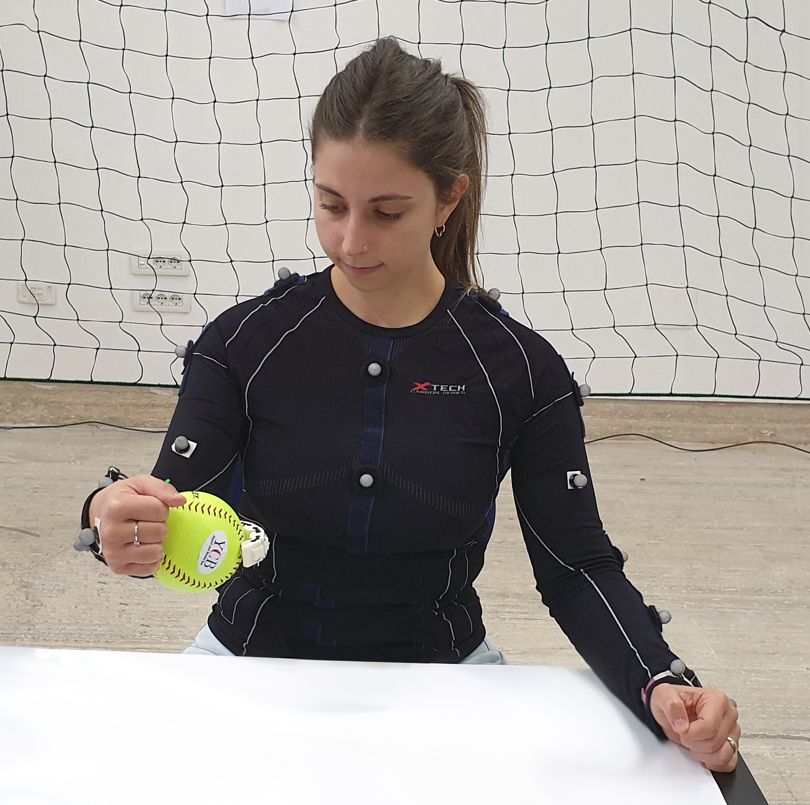
With this work, the Implicit Kinematic Kernel control paradigm is defined and applied to control wearable extra-fingers in a natural, comfortable, and intuitive way to help subjects with a limited mobility and/or physical impairments. To the best of our knowledge, this represents the first attempt to investigate the feasibility and usability of this novel control strategy for human-device interaction (Figure 1).
II Implicit Kinematic Kernel
II-A Definition
One of the main novelties introduced with this work concerns the concept of Implicit Kinematic Kernel. From the algebraic point of view, given a linear transformation , the kernel (or null space) of is the set of vectors such that . The same definition applied in robotics leads to the computation of the kinematic kernel: given the Jacobian matrix , where n and r are the dimensions of joints space and task space, respectively, the subspace is the set of joint velocities that do not produce any end-effector velocity in the given configuration of the manipulator. In a complementary way, the range space of the Jacobian , , is the set of end-effector velocities that can be generated by the joints motion in the given configuration of the manipulator. In the general case, and , meaning that the joints can provide at least the number of DoFs required for the end-effector task. If , the manipulator is said kinematically redundant. Thus, the concept of kinematic kernel is strictly related to the number n of DoFs of the robot. If has full rank (, ), the range of spans the entire space . Instead, if the Jacobian degenerates, the dimension of the range space decreases while the dimension of the null space increases. The relation holds independently of the rank of the matrix .
In this work, according to the definition of kinematic kernel in robotics, the redundancy of the human body, i.e. the fact that there are more degrees of freedom than those required for a certain task (), is exploited to control an additional degree of actuation. Adapting the concept of robotic kernel to the human body is not a straightforward operation: differently from a serial robotic manipulator, humans have more than one end-effector (i.e., hands and foots) and can perform multiple tasks at the same time. Thus, for identifying the exploitable degrees of freedom it is necessary to specify which is the considered end-effector and, consequently, the task we refer to. From this perspective, considering the kinematic space of the whole body, we can make a distinction between two types of kernel space:
-
i)
Explicit Kinematic Kernel (EKK);
-
ii)
Implicit Kinematic Kernel (IKK).
Considering a task to be accomplished, velocities of joints which are not involved in such a task belong to the first category, whereas the latter refers only to joints directly employed in the task. For instance, grabbing a box with two hands involves joints of shoulders, upper arms, forearms, and wrists. Motions of all the other joints (e.g., knees and ankles) are in the Explicit Kinematic Kernel space. On the contrary, the motion of the joints of shoulders, upper arms, forearms, and wrists which does not generate velocities of the hand belongs to the Implicit Kinematic Kernel space.
Bearing in mind the control of wearable robots, movements in the EKK space may be easier to distinguish, and thus to be extracted and associated to the device device control. However, they would limit users’ mobility by demanding the involvement of further joints beyond those required for the task execution. As mentioned in Section I, taking advantage of movements in the Implicit Kinematic Kernel space would let the user control a device using body parts already involved in the task, without compromising the use of free limbs which instead may be involved in further parallel tasks. For this reason, in this work we decided to exploit motions in the IKK space in the specific use case of controlling a wearable extra-finger. Among the huge number of possible motions of the human body, we focused our attention on single-arm tasks, since we identified them as the most crucial action for impaired people and the most paradigmatic for presenting this innovative approach. To identify the Implicit Kinematic Kernel in a simple single-arm task, the following procedure was adopted.
II-B Kernel Identification
Whereas in robotics computing the null space of a given kinematic chain configuration is a straightforward operation, this estimation is more challenging when applied to humans. The problem stems from the lack of simple kinematic models incorporating the wide range of constraints each human body can be subjected to. Besides the anatomy of the human musculoskeletal system, ages, habits, and motor skills strongly influence the way people interact with objects and the surrounding, with the outcome that each individual is prone to perform the same task in a different way. Thus, there is not a mathematical formula for estimating the human kinematic kernels. To overcome this problem, we developed a procedure to identify the Implicit Kinematic Kernel focusing on the case of a single-arm task.
Kinematic chain identification
As stated in its definition, the Implicit Kinematic Kernel concept is dependent on the performed task. For this reason, to estimate the current involved joints, it is fundamental to take into account some general knowledge on the morphology and the kinematic constraints of the human body, that determines which joints are required to perform a certain task. In other words, the kinematic chain involved in the task need to be a-priori identified.
For instance, considering a single-arm task, the end-effector is represented by the hand and consequently the significant chain is composed of the joints of shoulder, elbow, and wrist, and the associated links. All the joint velocity vectors including the user’s arm joints which do not contribute to change the hand velocity are then considered belonging to the IKK.
Joints motion analysis
Once the instructions to perform the task have been clearly defined, the user’s movements need to be recorded and analysed during the performance. Using a motion capture system, it is possible to reconstruct the body motion and estimate the joint values. As a general rule, we considered a joint angles vector as belonging to the IKK space if its contribution to the end-effector velocity is negligible with respect to the particular application.
In the considered case, we deemed the hand speed constant if its variation is lower than . These thresholds can be revised and refined for particular tasks.
Principal Component Analysis
At this stage, the multidimensional space of the kinematic kernel has to be projected in the supernumerary limb DoA space.
To this end, firstly, the acquired joint values are transformed through Principal Component Analysis (PCA) into a set of values of linearly uncorrelated variables called principal components. Indeed, PCA is particularly effective in dealing with a large number of system variables, e.g. the DoFs identified in the previous step. Secondly, depending on if the percentage of data variation explained by the first Principal Component is at least 80% or not, either this one or the norm of the first two PCs can be taken as a direction for controlling the intended DoA.
As introduced in Section I, the final objective of this work is the development of a framework for easily controlling an extra-finger. Thus, in order to control a single degree of actuation by exploiting a certain movement in the IKK, we project the IKK multidimensional space into the monodimensional space of the robotic extra-finger.
Workspace clustering
It is worth noticing that the kernel space, and thus the corresponding PC (or PCs), changes in accordance with the position of the end-effector, i.e., it depends on the actual value of the angle of the joints involved in the kinematic chain. Hence, in theory it is necessary to compute the kernel space (and consequently the PCs) for each point in the arm workspace. To avoid this, we developed a procedure to automatically find the kernel base in any point of the user’s workspace, given its value in a limited and predefined set of points.
Motions in different positions, namely ‘starting PCA points’, are recorded. These positions are chosen to cover a portion of the arm workspace, considering only the reachable region. Indeed, considering the entire available workspace is useless since in the boundaries the mobility of the considered body part is reduced. For instance, when the arm is fully extended (at the limit of the reachable workspace), it is not possible to impose an arbitrary motion to the arm without moving the hand. The PCs evaluated in each of the aforementioned positions are used to create an interpolation volume which will be used to evaluate the kernel space in any point of the selected portion of the workspace. In this way, we can compute a IKK-based control signal also in those points in which it has not been recorded.
To create the interpolation volume, data captured in the points are clustered and separately analysed to compute the PCs in each cluster.
The algorithm is based on the k-means approach and implements the following steps:
-
(1)
compute a minimal bounding box for the recorded points in 3D space;
-
(2)
select the initial coordinates to place the centres of the clusters (i.e., one for each ‘starting PCA point’) in the surface of the bounding box;
-
(3)
for each data point , compute , i.e. the distance between and each centroid, and assign each observation to the cluster with the closest centroid;
-
(4)
compute the average of the observations in each cluster to obtain new centroid locations;
-
(5)
repeat steps (3) through (5) until cluster assignments do not change, or the maximum number of iterations is reached.
As a conclusive step, to compute the PCs of each cluster, we consider only data laying in an appropriate neighbourhood of the centres. This threshold has to be experimentally evaluated and refined in accordance with the task characterization.
Considering the case of a single-arm task, the kernel space changes depending on the position of the hand (i.e., the end-effector) with respect to the whole body, and, thus, on the actual value of the arm joint angles in that configuration. This means that the kernel space when the hand is near the chest is different from the one when the arm is outstretched ahead.
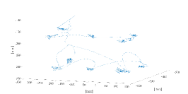
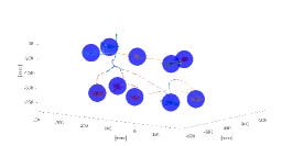
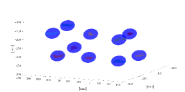
Figure 2 illustrates the steps leading to the workspace clustering starting from the data collection. In Figure 2a, the trajectory performed by the user is reported. In Figure 2b the identified clusters are depicted and highlighted with blue spheres. Finally, the considered points for computing the PCA are shown in Figure 2c.
Workspace interpolation
A fundamental requirement for controlling a wearable robotic extra-limb is the capability of working in real time manner. In the proposed implementation, the algorithm exploits the ‘starting PCA points’ to compute online and seamless the value for controlling the wearable robot. A three-dimensional Delaunay triangulation-based natural neighbour interpolation is used to reconstruct online the PC associated to the current kernel space [22]. The Delaunay triangulation is an established method to define neighbourhood relations in multi-particle systems. In this way, it is possible to compute the control signal in any point of the working space, depending on the posture of the user.
III Experiments Design
The goal of the experiments presented in this paper was to prove that the proposed methodology is effective for controlling an extra-finger in an intuitive and comfortable way. Moreover, we were interested in studying how the users learn a new control law. Finally, our aim was to evaluate how users perform ADLs using a physical prototype of the extra-finger in real time. To this end, a preliminary calibration phase and a step-wise validation procedure were carried out. In the calibration phase, each subject’s IKK was identified by applying the procedure described in Section II. Then, we validated the proposed framework both in virtual and real environments. The entire experimental validation was conducted bearing in mind the final usage of the extra-finger: open/close the device without moving the hand to grasp objects.
The study was approved by the Local Institutional Ethics Committee. Each participant gave her/his written informed consent to participate and was able to discontinue participation at any time during the experiments. The experimental evaluation protocols followed the declaration of Helsinki, and there was no risk of harmful effects on participants’ health. Data were recorded in conformity with the European General Data Protection Regulation 2016/679, stored on local repositories with anonymized identities (i.e., User1, User2), and used only for the post processing evaluation procedure. Please note that no sensible data were recorded.
Ten subjects participated in the experimental campaign. They were seven males and three females (from 22 to 57 years old, mean 354.5), all right-handed. None of them had previous experiences in controlling wearable robots. Each subject took part to the the entire experimental validation. Every experimental session consisted of a calibration procedure, followed by four experiments: two in a virtual, and two in a real environment. Between two subsequent trials, subjects were allowed to rest for more than an hour, and a preparatory phase of five minutes was provided at the beginning of each trial to acquaint them with the system.
All the experiments were performed in a room equipped with ten Vicon Bonita cameras. To record arm joint angle values, retro-reflective markers were attached to the subject, who was located at the centre of the room. Eight cameras were placed at the upper corners (two per corner, with a different orientation), while the remaining two were fixed to tripods placed on opposite sides of the room, on the left and right side of the subject, respectively. The body posture was reconstructed online by means of Vicon Nexus 3.10 Software (Vicon Motion Systems Ltd, UK), with a frame rate of .
III-A Calibration
User Skeleton Calibration
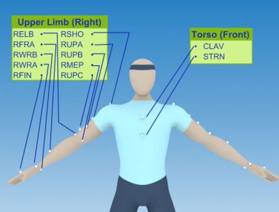
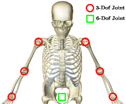
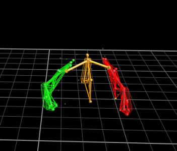
As a first step, 24 retro-reflective markers were attached to the subject in accordance with the Oxford Upper Body Model [21], following the schematic illustration reported in Figure 3a. To calibrate the system, each participant was asked to stand at the centre of the room for . A static acquisition and anthropometric measurements were used to create each user’s upper body skeleton model, consisting in 24 DoFs (as visually depicted in Figure 3b). An example of user-calibrated upper body skeleton is shown in Figure 3c.
IKK Identification
Once the skeleton had been modelled, a dedicated PC acquired images from the cameras. Thanks to the calibration procedure, the user’s skeleton is automatically reconstructed and the kinematic model is fitted online. This step enables the real time capturing of joint angle values and body segments positions. To gain awareness of the workspace, participants were asked to seat and explore the arm workspace with the hand without moving the torso. After one minute of free exploration, participants were told to visualize an imaginary parallelepiped covering their arm workspace and to select 10 points: 8 in the proximity of the vertexes and 2 at the centres of the upper and lower surfaces. To avoid arm singularities, participants were suggested to exclude points on the exact boundaries of the arm workspace. Participants were instructed to place the hand in each of the selected points and freely move the arm for five seconds, holding the hand as steady as possible (i.e., without changing position and orientation). They were asked to explore the entire range of motion available in each position, so as to record minimum and maximum reachable values. On the basis of the clusterization output (Figure 2), the procedure detailed in Section II-B selected meaningful data and computed the Principal Components for each of the ten points.
Once the 10-points grid had been prepared, the interpolation of the known Principal Components coefficients made possible to associate any hand position to its own Principal Component. Thus, when the user performed movements in the IKK space, a middleware was in charge of computing the projection of the current joint values to the actual Principal Component, depending on the current hand position. The resulting value was then used to control the additional DoA required by the particular task under investigation.
III-B Virtual Environment
With the goal of creating an interface as simple and intuitive as possible, subjects were instructed on the association between IKK movements and a virtual DoA. More in detail, the first experimental validation aimed at answering the following research questions:
-
i)
Is the generated control signal appropriate for attaining a desired behaviour?
-
ii)
Is it possible to use the IKK to control an extra degree of actuation to execute an additional task?
To answer these questions, two experiments were carried out.
Experiment 1 - Trajectory tracking
We started answering the first question by evaluating the user’s accuracy in a tracking task, i.e., in following a predefined reference profile exploiting the proposed control system. This kind of setup was thought to simulate the execution of precise opening/closing movements of the robotic extra-finger using the IKK space.
Three desired trajectories (depicted in Figure 4) were pseudo-randomly generated. The user was seated in front of a screen and was instructed to follow the displayed predefined profiles. This had to be done by using arm movements belonging to the IKK space to control the vertical displacement of a round red pointer, while the horizontal displacement was updated at constant velocity. Control values were normalized so as to range from 0 to 100. Each profile was repeated three times, for a total of nine trials per each subject. A time of five seconds was provided to reach the starting condition (i.e., to align the position of the pointer with the initial flat trend of the trajectory, see Figure 4), then a pop-up window informed the user about the starting of the experiment. During the trial, a red line joined the positions already reached by the pointer and informed the user about the progress. Each trajectory lasted , thus the total time of each trial was .
For the sake of comparison, we asked each subject to repeat the same experiment using a commercial gamepad (F310, Logitech, CH) as a control condition, being this device a gold standard for the results interpretation.
Experiment 2 - Spheres overlapping
In the second experiment, we aimed at answering to the second research question, i.e. whether it is possible to use the IKK space to control an additional degree of actuation while executing a different task in parallel. To this end, a virtual environment was developed through an ad-hoc C# software and rendered using an Oculus Rift DK2 [23].
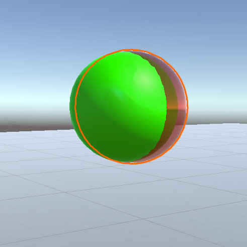
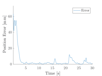
Participants were asked to seat and move their upper limb to control position and radius of a virtual sphere. The goal of the experiment was to overlap the two spheres: one controlled by the user and a target. Two different cases were tested. While in both cases the radius was changed by exploiting the Implicit Kinematic Kernel, in the second case the user had also to change the sphere position by moving the hand, as illustrated in Figure 5. In particular, the coordinates of the centre of the sphere corresponded to the coordinates of the marker positioned on the back of the right hand. In other words, in the second case two simultaneous tasks were required: the primary task was to centre the two spheres and the secondary task was to adapt the radius of the controlled sphere to match the target dimension.
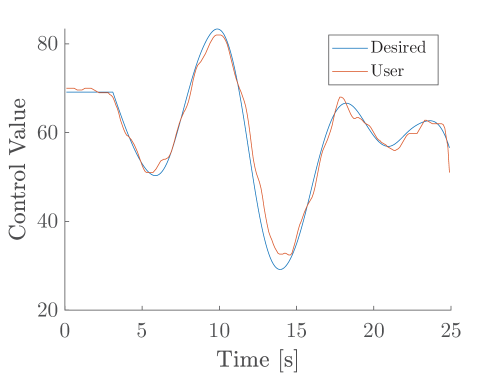
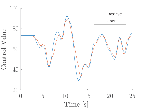
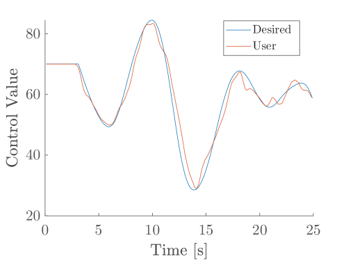
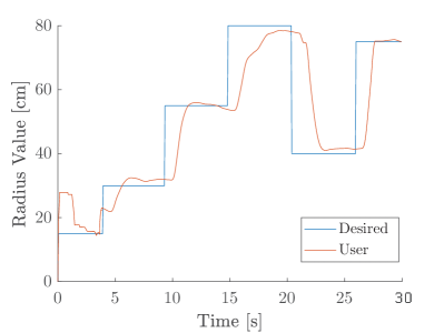
Three different target positions were tested, one per each trial. Trials started displaying on the head mounted display a tiny red sphere (indicating the current hand position) and an initial target sphere with radius. This initial phase lasted and served to let the user align the spheres centres. Then, the radius of the goal sphere changed six times, once every . A plot reporting the target radius value and the user’s controlled one in a representative trial is depicted in Figure 6.
Metrics of interest
While in the first experiment we considered only the performance in following a desired profile, in the second one errors in matching the radii (in both cases) and in correctly positioning the centres of the spheres (only for the second case) were considered as metrics of success in accomplishing the task. Therefore, performances in i) following a desired profile, ii) maintaining the hand in a steady position, and iii) matching the spheres radius were measured by means of the Root Mean Square Error (RMSE). For the sake of accuracy, it is worth noticing that for the performance on maintaining the hand in a steady position the considered error did not include the initial alignment. Similarly to [24], for each trial we defined the RMSE quantity as , where N is the number of samples in a trial, is the actual control value, and is the corresponding target value. Notice that the tracking RMSE is a suitable metric to evaluate the rapidity and the accuracy of the robot motions [25]. This is due to the fact that increases both if users are slow in adapting the control variable and if they miss the targets. In other words, human control has to be simultaneously fast and accurate to yield a low . The RMSEs were used to analyse the tracking performance throughout the whole experiment.
III-C Real Environment
The following experiments were conducted in order to assess the effectiveness of our system in a real scenario. More in detail, the experimental validation aimed at tackling the following research questions:
-
i)
Is the IKK-based control usable/easy to learn for controlling extra-fingers to perform simultaneous tasks?
-
ii)
Is the proposed approach suitable to accomplish common activities of daily living?
Also in this case, two experiments were carried out. In the first experiment, users performed a repetitive pick-and-place task, while in the second experiment the task was enriched adding multiple objects and different target locations. In both cases users wore the robotic extra-finger on the right forearm, mimicking a post-stroke hemiparesis, and controlled the opening/closing actuation with the same arm using the IKK. The wearable robotic finger utilised for the experiments is a modified version of the one presented in [26]. It is worth noticing that, to demonstrate the capability of the proposed approach, the degree of actuation of the extra-finger is controlled in continuous manner.
Experiment 3 - Single object pick and place
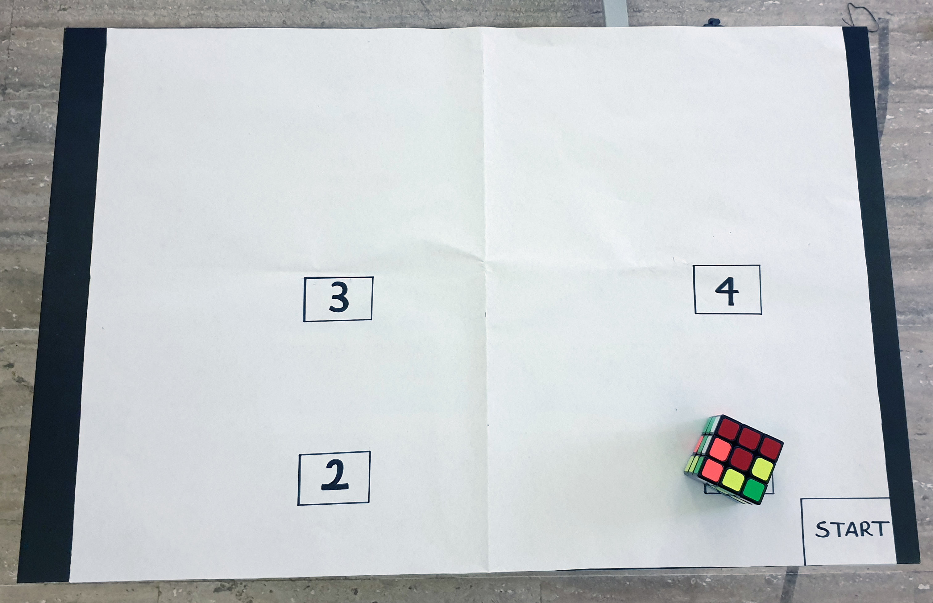
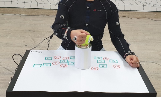
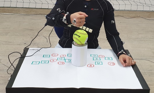
To evaluate the ease of learning the proposed control strategy, participants were asked to pick and place a Rubik’s Cube (see Table I for details) in four predefined points of the reachable arm workspace. These points are the corners of a rectangular area, as depicted in Figure 7. Participants were instructed to pick the cube and place it from one point to the next following the rectangle perimeter (clockwise) as many times as possible in a time limit of 3 minutes. The starting point was on the right lower angle of the arm workspace, and the number of successfully reached target positions was considered as a performance metric. Each target position was considered successfully reached (thus, it was counted in the final value) if the cube was correctly placed on it and the subject had opened the extra-finger and raised the hand by around 10 cm. Users repeated the experiment 7 times, with a pause of 15 minutes between each iteration.
Experiment 4 - Multiple objects pick and place
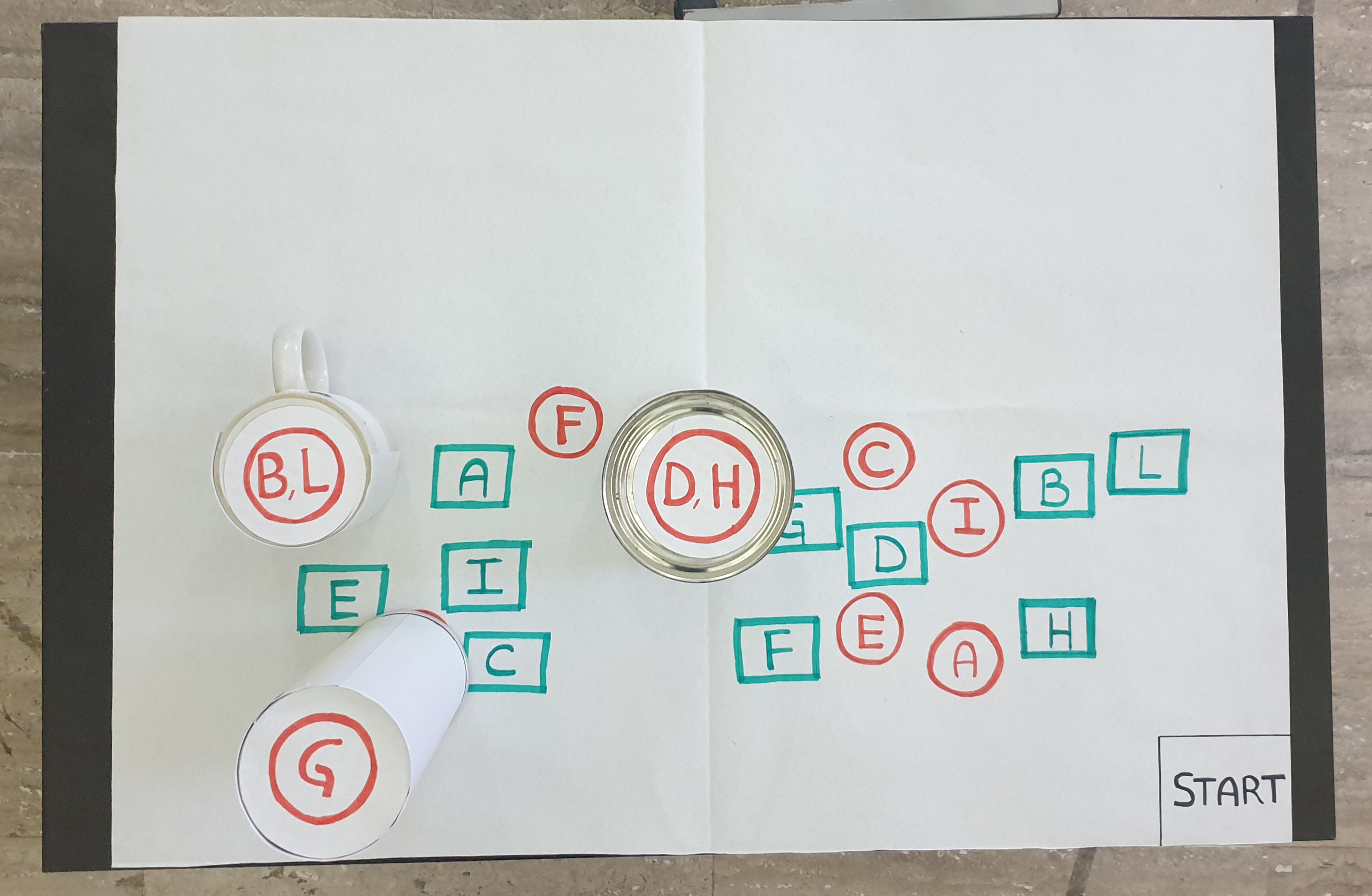
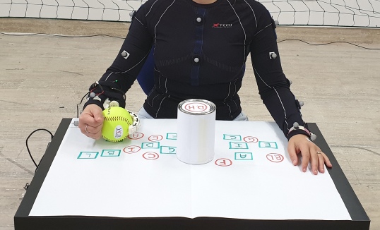
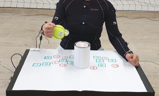
In this experiment, subjects were asked to seat in front of a table and pick and place 10 objects taken from the YCB benchmark set [27]. Details on the objects are reported in Table I. Objects were positioned on the table one at a time and each object was identified with an alphabetical code. The initial and target locations for the objects were marked on the table, with predefined start and goal positions: start positions were represented with a green square, whereas the goal positions were marked with a red circle (see Figure 8). All the participants performed the same pick-and-place tasks. Participants were instructed to pick, lift, and place in the correct position each object, as fast as possible and using only the right arm. Each pick-and-place task was considered successfully accomplished if the object was not dropped during the execution and the elapsed time for the single pick-and-place task did not exceed . A depiction of the scenarios can be found in Figure 9. For the sake of comparison, we asked each subject to repeat the experiment using the same extra-finger controlled with a ring embedding a push button switch for opening/closing. This controller was considered as the fastest and easiest controlling technique for operating the robotic finger.
| Code | Object | Weight [g] | Dimensions [mm] |
| A | Rubik’s Cube | 84 | 60 x 60 x 60 |
| B | Soft Ball | 191 | 96 |
| C | Chips Can | 205 | 75 x 250 |
| D | Tomato Soup Can | 349 | 66 x 101 |
| E | Cups 1 | 14 | 60 x 62 |
| F | Cups 2 | 21 | 75 x 68 |
| G | Cups 3 | 28 | 85 x 72 |
| H | Cups 4 | 35 | 95 x 76 |
| I | Apple | 68 | 75 |
| L | Wine glass | 133 | 89 x 137 |
| M | Potted Meat Can | 370 | 50 x 97 x 82 |
Metrics of interest
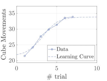
Time to accomplish the task and performance in terms of number of successes and failures were considered as performance metrics for evaluating the system. Additionally, outcomes of Experiment 3 were used to estimate the learning curve and to identify the potential limits of the system. The theory of the learning curve is based on the concept that the time required to perform a task (for instance, approach, grab, and move the Rubik’s Cube) decreases at a constant rate as the user gains experience [28]. To assess a measure of learning, we used the sigmoid curve proposed in [29] for fitting purposes,
where is the trial number, is the curve shape parameters vector, and is the minimum observed performance. The resulting unconstrained minimization problem (UMP) is
where is the trial number and is the corresponding number of cube movements within 3 minutes. The dependency on the initial guess, consequence of the UMP non-convexity, was mitigated in a genetic fashion by randomizing the initial guess and storing the best solution.
III-D Questionnaire
Finally, at the end of the whole experimental session, each user anonymously filled an on-line questionnaire based on the Usefulness Satisfaction and Ease-of-use questionnaire (USE, [30]) that focuses on the experience of the system usage111The questionnaire is available at: https://www3.diism.unisi.it/~lisini/questionnaires/USE.html.
These surveys uses a seven-point Likert rating scale. The marks range from “= strongly disagree”to “7 = strongly agree”. Means and standard deviations (STD) of the scores are presented in Table II.
IV Results and Discussion
This section reports a-posteriori discussions on the experimental results, supported by a statistical analysis.
IV-A Virtual Environment
In the course of Experiment 1 and Experiment 2, participants exploited movements in the IKK space both for following a predefined reference profile and for modifying the radius of a sphere. The two experiments served as a mean for answering the research questions outlined in Section III-B.
Experiment 1 - Trajectory tracking
This experiment tackled the first scientific question, i.e. “Is the generated control signal appropriate for attaining a desired behaviour?”
The Root Mean Square Error was used as evaluation metric. Results for each user are reported in Table IV. Outcomes show a small RMSE in performing the experiment using the IKK-based control. The mean error obtained in each trajectory among the participants is lower than 5.5: considering a control value ranging from 0 to 100, it represents the 5.5% of the maximum control value (MCV). These values are comparable with those obtained using the gamepad controller. A statistical analysis was conducted to compare results obtained with IKK-based and gamepad controller. A paired-samples t-test revealed that there is no statistically significant difference between the mean RMSEs recorded in the two conditions (, , ). No outliers were detected and the assumption of normality was not violated, as assessed by Shapiro-Wilk’s test (, ).
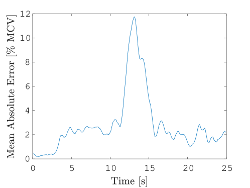
In addition, a careful examination of the lower panels of Figure 4 makes evident that the absolute error is lower than 4.0 when the desired profile is smoothly changing, while reaches greater values when the user is requested to follow rapid changes of the path. With both the control strategies, the highest error derives from the second trajectory (Figure 4b), which requires the user to rapidly modify the control value moving from 90 to about 30 in less than 3 seconds. Conversely, the first trajectory (Figure 4a) requires the user to perform slower movements and the mean error for the IKK-based control is less than 10 for each participant.
Experiment 2 - Spheres overlapping
Once preliminary findings assessed the capability of exploiting the proposed methodology, we proceeded with the experimental validation by evaluating the feasibility of executing two tasks simultaneously. Notably, the opportunity of performing multiple tasks with the same body part is one of the novelties presented in this work. Thus, answering to the question “Is it possible to use the IKK to control an extra degree of actuation to execute an additional task?” represents a key point for the overall evaluation. Additionally, people wearing extra-fingers often require to simultaneously accomplish multiple tasks (such as grabbing a bottle and unscrewing the cap, stabilizing an apple and peeling it, etc.), therefore the feasibility of associating the control interface to the arm that wears the device needs to be assessed. To this aim, we designed Experiment 2 to evaluate the user ability in carrying out two tasks at the same time, both involving the same kinematic chain.
Results of Experiment 2 are reported in Table V. For assessing the feasibility of using the IKK-based control to fulfil an additional task, we compared the user performance achieved in the aforementioned case with those obtained when using the kernel is the only task required. This way, the first case (the one with only the IKK-based task) served as reference for evaluating the performance obtained when performing parallel tasks. Concerning the results of the second case, if both the RMSEs on the primary and secondary tasks are low and comparable, the proposed strategy is considered effective. On the contrary, an unbalanced performance output indicates that the IKK-based approach is too demanding or not suitable for the purpose.
We considered RMS errors in adjusting the radius in both cases (with and without the requirement on hand positioning). Results showed that the proposed approach is feasible. Indeed, the difference between the average RMSE among all the trials for all the participants in both cases are comparable (Single Task = 15.301.89 , Multiple Tasks = 15.812.08 ). In addition, the error on the hand positioning task (second case) shows that participants did not lose focus on the primary task despite the increased cognitive load required by the experiment (mean RMSE = 4.372.09 ). A paired-samples t-test was used to determine whether there was a statistically significant mean difference between the radii RMS error obtained when participants exploited the system to accomplish a single task compared to the the case in which they were asked to perform two tasks simultaneously. No outliers were detected. The assumption of normality was not violated, as assessed by Shapiro-Wilk’s test (). Result of the test revealed that the increase of between the two conditions is not statistically significant, , , .
Supported by the obtained results and leveraging the users’ feedback (discussed at the end of this section), we can affirm that the proposed control technique satisfies the two matters pointed out at the beginning of Section III-C.
IV-B Real Environment
In what follows, we analyse and discuss results concerning the experimental validation conducted with a wearable robotic extra-finger. As stated in Section III-C, the two questions to answer were:
-
i)
Is the IKK-based control usable/easy to learn for guiding additional limbs while performing simultaneous tasks?
-
ii)
Is the proposed approach suitable to accomplish common activities of daily living?
Experiment 3 - Single object pick and place
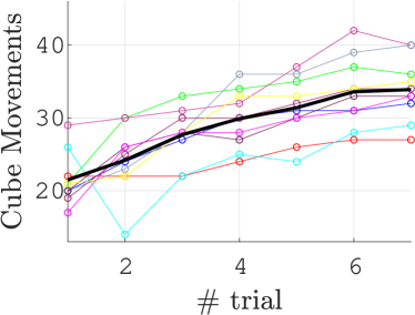
To address the first question, the number of cube placements in 3 minutes trials performed in Experiment 3 was used as performance metric. Figure 10 shows the fitting curves alongside the averaged experimental data collected in 7 trials. Results show that participants rapidly gained confidence and learned how to use the system. The majority of the users (8 over 10) reached a speed of 30 motions in three minutes, and half of them (4 over 8) did not reach the plateau. On average, after 7 trials (a total of 21 minutes of experiments) participants reached the plateau, with limited improvement capacity. The slope of the learning curve demonstrates that it is easy to learn how to use the system: on average, in no more than 6 trials (18 minutes of usage) the number of cube movements increased of about the 80%.
Experiment 4 - Multiple objects pick and place
Finally, with Experiment 4 we evaluated the system in a representative ADLs task (such as picking, moving, and placing real objects) by time-wise comparing performances obtained in two trials, one involving the ring embedding the push button switch control and one the IKK-based control. Results for the two trials are reported in Table VI and Table VII, respectively.
As introduced in Section III-C, we compared the time in picking and placing object with the system proposed in [11]. Opening and closing the extra-finger with a push-button located in the hand not involved in the task was considered the easiest and fastest way for commanding the wearable robot. For each user and for each object we report the time needed to accomplish the task. Exploiting the IKK-based approach, users took on average 8.943.26 to accomplish a pick-and-place task (failed attempts are not considered), while they needed 6.340.71 when repeating the task with the ring-based controller. As expected, elapsed times in the latter case are lower for all the users and for all the objects. The reason why this is not a surprising result is that people are generally familiar with controlling robotic devices using buttons. Moreover, the small standard deviation recorded among the trials further highlights the predisposition of users in using this interface and confirms that this is the best case to compare with. Differently, the IKK-based control system has larger standard deviations. We interpreted this aspect as an index of the fact that users need more time and more practice to gain further confidence and acquaintance with the system. Finally, it is worth noticing that the higher number of failures of object I (i.e., the apple) was due to the particular shape of the object. All the other objects have at most one failure.
To reinforce our hypothesis, we conducted a statistical analysis on the data. Times needed for moving each object with the ring and with the IKK-based control were compared. Trials in which users failed were removed and not considered in the analysis. Data were neither normally distributed, nor symmetrical with respect to the median. Thus an exact sign test was used to compare the performance differences among the two trials. Outcomes of the test confirmed that performing the trials with the IKK-based controller elicited a statistically significant median increase in time () compared to the ring modality, .
| Dimensions of usability |
|
||
|---|---|---|---|
| Usefulness (USE) | 5.30.6 | ||
| Ease of Use (EoU) | 5.41.0 | ||
| Ease of Learning (EoL) | 6.10.7 | ||
| Satisfaction (SAT) | 4.91.5 |
IV-C Users’ feedback and opinion
As a conclusive mean of evaluation, we analysed outcomes of the users’ opinions surveys. Scores were grouped by topic: USE (Usefulness), EoU (Ease of Use), EoL (Ease of Learning), SAT (Satisfaction). Answers mean and standard deviation are reported in Table II, while a graphical representation of the percentages distribution is in Figure 11. Participants to the experimental campaign rated positively the entire system. The Ease of Use and Ease of Learning are the most appreciate features, due to the simplicity and naturalness of the control technique. On the other hand, the satisfaction in using the system received the lowest scores. The two statements222Please refer to https://www3.diism.unisi.it/~lisini/questionnaires/USE.html “26. It is fun to use” and “30. It is pleasant to use” received an average of 4.21.4 and 4.31.6, respectively. These results are not surprising: indeed, the system is not thought to be fun, but its main goal is to provide help to people with upper arm impairments. This aspect is further supported by the high scores obtained on the usefulness of the system. Finally, for what concerns the Ease of Use and Ease of Learning, users’ feedback (EoU 5.41.0, EoL 6.10.7) are in line with the numerical results of the learning curve and the time to accomplish ADL tasks.
V Conclusions and future work
This study presented a new approach for controlling wearable robotic extra-fingers exploiting the redundancy of the human body. This kind of control takes advantage of movements in the Implicit Kinematic Kernel space to enable the user to easily and comfortably control wearable robots.
First, we tested the proposed methodology in a virtual environment, proving its reliability and verifying it does not affect the performance of the primary task. Then, we used the IKK-based control method in the real environment, assessing that it is easy to learn and easy to use in ADL tasks. Results of the experimental evaluation , supported by users’ feedback and opinions, revealed that the proposed control strategy is suitable for controlling an extra-finger in the envisaged scenario.
Future research directions include expanding this IKK-based control strategy to govern a larger number of degrees of freedom.
| DoF | Degree of Freedom |
|---|---|
| ADL | Activity of Daily Living |
| DoA | Degree of Actuation |
| J | Jacobian |
| IKK | Implicit Kinematic Kernel |
| EKK | Explicit Kinematic Kernel |
| Null space (kernel) of matrix A | |
| Range space of matrix A | |
| PC | Principal Component |
| PCA | Principal Component Analysis |
| RMS | Root Mean Square |
| RMSE | Root Mean Square Error |
| Gamepad controller | IKK-based controller | |||||
| User | Trajectory1 | Trajectory2 | Trajectory3 | Trajectory1 | Trajectory2 | Trajectory3 |
| User1 | 4.20 | 5.82 | 2.74 | 4.64 | 6.92 | 5.39 |
| User2 | 4.14 | 2.89 | 3.04 | 3.3 | 5.22 | 3.18 |
| User3 | 4.26 | 4.41 | 4.13 | 3.17 | 5.68 | 4.42 |
| User4 | 3.23 | 4.36 | 4.68 | 3.79 | 6.42 | 2.82 |
| User5 | 3.10 | 3.58 | 3.69 | 2.65 | 4.49 | 3.59 |
| User6 | 3.45 | 4.26 | 2.96 | 4.61 | 5.46 | 4.85 |
| User7 | 5.37 | 7.03 | 5.92 | 2.24 | 4.32 | 7.56 |
| User8 | 5.19 | 6.68 | 5.80 | 2.36 | 4.42 | 3.68 |
| User9 | 4.49 | 5.75 | 4.21 | 3.5 | 6.47 | 6.35 |
| User10 | 3.86 | 5.19 | 4.34 | 3.3 | 4.98 | 3.23 |
| Mean STD | 4.13 0.76 | 4.98 1.33 | 4.15 1.10 | 3.35 0.83 | 5.43 0.92 | 4.50 1.54 |
| Single Task | Multiple Tasks | ||||||||||||
|
|
|
|
||||||||||
| Trial 1 | Trial 2 | Trial 3 | Trial 1 | Trial 2 | Trial 3 | Trial 1 | Trial 2 | Trial 3 | |||||
| User1 | 12.56 | 17.17 | 15.80 | 13.00 | 14.49 | 13.81 | 8.05 | 2.43 | 2.34 | ||||
| User2 | 14.01 | 16.00 | 16.00 | 14.95 | 15.31 | 15.15 | 2.50 | 3.52 | 6.11 | ||||
| User3 | 15.81 | 17.46 | 21.37 | 14.01 | 18.00 | 21.75 | 4.59 | 9.03 | 3.31 | ||||
| User4 | 18.00 | 17.55 | 19.23 | 16.22 | 16.38 | 18.24 | 4.20 | 8.53 | 4.10 | ||||
| User5 | 14.78 | 16.22 | 17.61 | 14.01 | 16.94 | 18.54 | 4.05 | 9.03 | 5.43 | ||||
| User6 | 13.69 | 16.62 | 15.15 | 14.95 | 12.98 | 16.30 | 3.50 | 7.33 | 2.55 | ||||
| User7 | 12.45 | 15.49 | 17.07 | 15.80 | 13.85 | 14.52 | 5.74 | 2.94 | 2.33 | ||||
| User8 | 12.74 | 17.00 | 15.15 | 13.60 | 14.72 | 13.84 | 2.83 | 4.37 | 2.89 | ||||
| User9 | 13.05 | 15.71 | 15.07 | 13.54 | 15.23 | 14.64 | 2.84 | 3.28 | 2.44 | ||||
| User10 | 12.37 | 15.80 | 17.52 | 14.46 | 14.72 | 15.11 | 3.48 | 4.30 | 3.04 | ||||
| Mean STD | 15.81 2.08 | 15.30 1.89 | 4.37 2.09 | ||||||||||
| Object | User1 | User2 | User3 | User4 | User5 | User6 | User7 | User8 | User9 | User10 | Mean | N. Fails |
| A | 7.3 | 8.0 | 12.0 | 11.1 | 12.0 | 12.5 | 10.2 | 8.46 | 10.4 | 4.5 | 10.2 | 0 |
| B | 10.7 | 6.4 | 7.2 | 9.0 | 5.3 | 7.0 | FAIL | 14.0 | 6.6 | 5.0 | 8.3 | 1 |
| C | 7.5 | 13.0 | 8.5 | 16.5 | 6.0 | 12.2 | 14.8 | 6.8 | 4.6 | 5.7 | 10.0 | 0 |
| D | 8.5 | 10.0 | 5.6 | 18.0 | 6.4 | 19.2 | 8.9 | FAIL | 5.6 | 4.8 | 10.3 | 1 |
| E | 7.8 | 17.2 | 5.5 | 7.5 | 7.5 | 18.6 | FAIL | 10.9 | 11.8 | 4.9 | 10.9 | 1 |
| F | 6.2 | 8.5 | 6.2 | 7.4 | 12.3 | 6.6 | 6.2 | 9.3 | 5.8 | 4.8 | 7.6 | 0 |
| G | 9.3 | 11.8 | 5.6 | 5.9 | FAIL | 6.3 | 11.9 | 6.3 | 6.3 | 8.1 | 7.9 | 1 |
| H | 5.0 | 9.2 | 9.8 | 10.5 | FAIL | 9.7 | 12.4 | 8.0 | 7.7 | 5.7 | 9.0 | 1 |
| I | 7.2 | 11.0 | 7.2 | 8.1 | FAIL | FAIL | 12.0 | FAIL | 9.2 | FAIL | 9.1 | 4 |
| L | 9.3 | 18.3 | 6.6 | 7.3 | FAIL | 7.1 | FAIL | 7.4 | FAIL | 7.2 | 9.3 | 3 |
| Mean | 7.88 | 11.34 | 7.43 | 10.12 | 8.28 | 11.05 | 10.93 | 8.93 | 7.60 | 5.62 | ||
| STD | 1.65 | 3.89 | 2.12 | 4.08 | 3.08 | 5.02 | 2.75 | 2.52 | 2.41 | 1.25 |
| Object | User1 | User2 | User3 | User4 | User5 | User6 | User7 | User8 | User9 | User10 | Mean |
| A | 8.20 | 8.01 | 7.20 | 8.45 | 7.50 | 6.93 | 6.00 | 5.37 | 5.90 | 5.85 | 6.94 |
| B | 8.78 | 8.03 | 7.38 | 8.10 | 6.63 | 5.33 | 4.76 | 6.18 | 5.33 | 5.52 | 6.60 |
| C | 7.55 | 7.83 | 7.48 | 7.88 | 8.03 | 5.45 | 5.58 | 6.01 | 5.65 | 7.15 | 6.86 |
| D | 6.30 | 6.70 | 7.13 | 6.62 | 5.86 | 5.65 | 5.00 | 5.70 | 4.72 | 5.46 | 5.91 |
| F | 5.83 | 6.00 | 6.71 | 6.43 | 5.71 | 5.25 | 5.45 | 6.10 | 6.18 | 5.40 | 5.91 |
| G | 6.25 | 5.68 | 6.68 | 6.42 | 5.90 | 5.40 | 5.42 | 5.43 | 5.20 | 5.93 | 5.83 |
| H | 6.51 | 5.68 | 4.80 | 4.30 | 5.22 | 6.29 | 6.12 | 5.96 | 4.60 | 5.45 | 5.49 |
| I | 7.16 | 11.58 | 7.08 | 6.86 | 7.02 | 6.30 | 5.90 | 5.20 | 5.66 | 6.11 | 6.89 |
| L | 5.63 | 7.70 | 4.51 | 5.52 | 4.43 | 4.66 | 5.16 | 5.48 | 5.36 | 6.10 | 5.46 |
| Mean | 7.10 | 7.63 | 6.77 | 6.95 | 6.48 | 5.77 | 5.71 | 5.73 | 5.42 | 5.84 | 6.34 |
| STD | 1.18 | 1.80 | 1.26 | 1.42 | 1.28 | 0.69 | 0.83 | 0.34 | 0.49 | 0.54 | 0.71 |
References
- [1] B. E. Lawson, J. Mitchell, D. Truex, A. Shultz, E. Ledoux, and M. Goldfarb, “A robotic leg prosthesis: Design, control, and implementation,” IEEE Robotics & Automation Magazine, vol. 21, no. 4, pp. 70–81, 2014.
- [2] A. E. Schultz and T. A. Kuiken, “Neural interfaces for control of upper limb prostheses: the state of the art and future possibilities,” PM&R, vol. 3, no. 1, pp. 55–67, 2011.
- [3] P. Shenoy, K. J. Miller, B. Crawford, and R. P. Rao, “Online electromyographic control of a robotic prosthesis,” IEEE transactions on biomedical engineering, vol. 55, no. 3, pp. 1128–1135, 2008.
- [4] A. Jackson and J. B. Zimmermann, “Neural interfaces for the brain and spinal cord—restoring motor function,” Nature Reviews Neurology, vol. 8, no. 12, p. 690, 2012.
- [5] A. M. Dollar and H. Herr, “Lower extremity exoskeletons and active orthoses: Challenges and state-of-the-art,” IEEE Transactions on robotics, vol. 24, no. 1, pp. 144–158, 2008.
- [6] F. Parietti, K. Chan, and H. H. Asada, “Bracing the human body with supernumerary robotic limbs for physical assistance and load reduction,” in 2014 IEEE International Conference on Robotics and Automation (ICRA). IEEE, 2014, pp. 141–148.
- [7] I. Hussain, G. Spagnoletti, G. Salvietti, and D. Prattichizzo, “Toward wearable supernumerary robotic fingers to compensate missing grasping abilities in hemiparetic upper limb,” The International Journal of Robotics Research, vol. 36, no. 13-14, pp. 1414–1436, 2017.
- [8] L. R. Hochberg, D. Bacher, B. Jarosiewicz, N. Y. Masse, J. D. Simeral, J. Vogel, S. Haddadin, J. Liu, S. S. Cash, P. Van Der Smagt et al., “Reach and grasp by people with tetraplegia using a neurally controlled robotic arm,” Nature, vol. 485, no. 7398, pp. 372–375, 2012.
- [9] M. Bortole, A. Venkatakrishnan, F. Zhu, J. C. Moreno, G. E. Francisco, J. L. Pons, and J. L. Contreras-Vidal, “The h2 robotic exoskeleton for gait rehabilitation after stroke: early findings from a clinical study,” Journal of neuroengineering and rehabilitation, vol. 12, no. 1, p. 54, 2015.
- [10] T. Zhang, M. Tran, and H. H. Huang, “Nrel-exo: A 4-dofs wearable hip exoskeleton for walking and balance assistance in locomotion,” in 2017 IEEE/RSJ International Conference on Intelligent Robots and Systems (IROS). IEEE, 2017, pp. 508–513.
- [11] I. Hussain, L. Meli, C. Pacchierotti, and D. Prattichizzo, “A soft robotic supernumerary finger and a wearable cutaneous finger interface to compensate the missing grasping capabilities in chronic stroke patients,” in Proc. IEEE World Haptics Conference. IEEE, 2017, pp. 183–188.
- [12] T. Noritsugu, H. Yamamoto, D. Sasakil, and M. Takaiwa, “Wearable power assist device for hand grasping using pneumatic artificial rubber muscle,” in SICE 2004 annual conference, vol. 1. IEEE, 2004, pp. 420–425.
- [13] C. D. Takahashi, L. Der-Yeghiaian, V. Le, and S. C. Cramer, “A robotic device for hand motor therapy after stroke,” in 9th International Conference on Rehabilitation Robotics, 2005. ICORR 2005. IEEE, 2005, pp. 17–20.
- [14] Y. Hasegawa, Y. Mikami, K. Watanabe, Z. Firouzimehr, and Y. Sankai, “Wearable handling support system for paralyzed patient,” in 2008 IEEE/RSJ International Conference on Intelligent Robots and Systems. IEEE, 2008, pp. 741–746.
- [15] H. In, B. B. Kang, M. Sin, and K.-J. Cho, “Exo-glove: A wearable robot for the hand with a soft tendon routing system,” IEEE Robotics & Automation Magazine, vol. 22, no. 1, pp. 97–105, 2015.
- [16] D. Prattichizzo, M. Malvezzi, I. Hussain, and G. Salvietti, “The sixth-finger: a modular extra-finger to enhance human hand capabilities,” in The 23rd IEEE International Symposium on Robot and Human Interactive Communication. IEEE, 2014, pp. 993–998.
- [17] I. Hussain, G. Salvietti, L. Meli, C. Pacchierotti, D. Cioncoloni, S. Rossi, and D. Prattichizzo, “Using the robotic sixth finger and vibrotactile feedback for grasp compensation in chronic stroke patients,” in 2015 IEEE International Conference on Rehabilitation Robotics (ICORR). IEEE, 2015, pp. 67–72.
- [18] I. Hussain, G. Salvietti, and D. Prattichizzo, “On control interfaces for the robotic sixth finger,” in Proceedings of the 7th Augmented Human International Conference 2016, 2016, pp. 1–2.
- [19] G. Salvietti, I. Hussain, D. Cioncoloni, S. Taddei, S. Rossi, and D. Prattichizzo, “Compensating hand function in chronic stroke patients through the robotic sixth finger,” IEEE Transactions on Neural Systems and Rehabilitation Engineering, vol. 25, no. 2, pp. 142–150, 2016.
- [20] V. Zatsiorsky, “Kinematics of human motion, human kinetics,” Urbana Champaign, 1998.
- [21] Vicon Motion Systems Ltd UK, “Vicon Nexus Full Body Plugin Gait.”
- [22] F. Cazals, J. Giesen, and M. Yvinec, “Delaunay triangulation based surface reconstruction: a short survey,” 2004.
- [23] P. R. Desai, P. N. Desai, K. D. Ajmera, and K. Mehta, “A review paper on oculus rift-a virtual reality headset,” arXiv preprint arXiv:1408.1173, 2014.
- [24] F. Parietti and H. H. Asada, “Independent, voluntary control of extra robotic limbs,” in 2017 IEEE International Conference on Robotics and Automation (ICRA). IEEE, 2017, pp. 5954–5961.
- [25] J. W. Krakauer and P. Mazzoni, “Human sensorimotor learning: adaptation, skill, and beyond,” Current opinion in neurobiology, vol. 21, no. 4, pp. 636–644, 2011.
- [26] D. Prattichizzo, M. Malvezzi, I. Hussain, and G. Salvietti, “The sixth-finger: a modular extra-finger to enhance human hand capabilities,” in Proc. IEEE Int. Symp. in Robot and Human Interactive Communication, Edinburgh, United Kingdom, 2014, pp. 993–998.
- [27] B. Calli, A. Singh, A. Walsman, S. Srinivasa, P. Abbeel, and A. M. Dollar, “The ycb object and model set: Towards common benchmarks for manipulation research,” in Proc. IEEE Int. Conf. on Advanced Robotics . IEEE, 2015, pp. 510–517.
- [28] P. S. Adler and K. B. Clark, “Behind the Learning Curve: A Sketch of the Learning Process,” Management Science, vol. 37, no. 3, pp. 267–281, 1991.
- [29] J. Han and C. Moraga, “The influence of the sigmoid function parameters on the speed of backpropagation learning,” in International Workshop on Artificial Neural Networks, 1995, pp. 195–201.
- [30] A. M. Lund, “Measuring usability with the USE questionnaire,” Usability interface, vol. 8, no. 2, pp. 3–6, 2001.