Millimeter-Wave Massive MIMO Testbed with Hybrid Beamforming
Abstract
Massive multiple-input multiple-out (MIMO) technology is vital in millimeter-wave (mmWave) bands to obtain large array gains. However, there are practical challenges, such as high hardware cost and power consumption in such systems. A promising solution to these problems is to adopt a hybrid beamforming architecture. This architecture has a much lower number of transceiver (TRx) chains than the total antenna number, resulting in cost- and energy-efficient systems. In this paper, we present a real-time mmWave () massive MIMO testbed with hybrid beamforming. This testbed has a 64-antenna/16-TRx unit for beam-selection, which can be expanded to larger array sizes in a modular way. For testing everything from baseband processing algorithms to scheduling and beam-selection in real propagation environments, we extend the capability of an existing 100-antenna/100-TRx massive MIMO testbed (below ), built upon software-defined radio technology, to a flexible mmWave massive MIMO system.
Index Terms:
Beam-selection, beamforming, massive multiple-input multiple-out (MIMO), millimeter-wave (mmWave), testbed.I Introduction
Massive multiple-input multiple-out (MIMO) is a promising multi-user (MU)-MIMO technology where each base station (BS) is equipped with an excess number of antennas, compared to the number of user equipments, e.g., a few hundred BS antennas simultaneously serving tens of UEs. The concept of massive MIMO has been demonstrated to achieve an order-of-magnitude higher spectral efficiency with practical acquisition of channel state information (CSI), as compared to conventional small-scale MIMO technology [1, 2]. In recent years, the development of massive MIMO prototype systems, operating below-, has been carried out for proof-of-concept and performance evaluation under real-world conditions [3, 4].
Another key approach to enhance the network capacity is the operation in millimeter-wave (mmWave) bands, i.e., – [5]. It provides an order-or-magnitude more spectrum than we ever had access to. At the mmWave bands, a large-scale antenna system, i.e., massive MIMO, is imperative to obtain sufficient signal-to-noise ratio (SNR) due to its high free-space path loss (FSPL) [6]. However, there are fundamental differences between the design and implementation of massive MIMO below- and at mmWave frequencies. The main differences are summarized as follows:
-
•
The architectures: the small wavelength at mmWave frequencies enables a large number of antennas in a small physical size. However, the current high cost and power consumption of the transceiver (TRx) chains at mmWave frequencies make a fully-digital processing approach prohibitive. Hybrid analog and digital beamforming can be an alternative architecture for mmWave massive MIMO systems [7, 8]. This architecture has a much lower number of TRx chains than the total number of antennas.
-
•
The propagation channels: propagation environments have a different effect on smaller wavelength signals. For example, diffraction, scattering, and penetration losses. It leads into different statistics of both small-scale and large-scale variations [9].
-
•
The baseband processing algorithms: depend on hardware, as well as channel characteristics. As compared with below- systems, the mmWave system is more sensitive to hardware impairments, such as phase noise, power amplifier (PA) nonlinearities [10, 11]. Thus, baseband processing algorithms for impairment estimation and compensation are crucial in mmWave systems.
Based on these differences, for testing everything from baseband processing algorithms to scheduling in new environments, we extend the capability of an existing 100-antenna/100-TRx massive MIMO testbed (below ), built upon software-defined radio (SDR) technology, to a flexible mmWave massive MIMO system. Recently, we have demonstrated this real-time mmWave massive MIMO system at IEEE Wireless Communication and Networking Conference in 2020 [8].
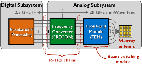
In this paper, we provide an overview of our real-time massive MIMO testbed, which includes a hybrid beamforming architecture based on beam selection, as illustrated in Fig. 1. Our testbed constitutes a flexible platform that supports up to 64-antenna/16-TRx BS, simultaneously serving a maximum of 12 UEs using orthogonal frequency division multiplexing (OFDM) in time-division duplex (TDD) mode.
II Testbed Architecture
In this section, we overview the architecture of our testbed. As illustrated in Fig. 1, the proposed testbed is divided into analog and digital subsystems. The physical hardware setup for the digital subsystem is in part identical with the 100-antenna/100-TRx Lund University massive MIMO (LuMaMi) testbed [4]. To extend this to mmWave, we have developed the required analog subsystem in-house.
The digital subsystem consists of a central control unit and SDRs (NI USRP-294xR/295xR), responsible for baseband and intermediate frequency (IF) processing. The central control unit has an embedded controller (NI PXIe-8135), which runs LabVIEW on a standard Windows 7 64-bit operating system to configure and control the system. LabVIEW provides both host and FPGA programming. To perform MIMO processing, e.g., precoding, detection, we use co-processing modules (FlexRIO 7976R). Also, a reference clock source (PXIe-6674T) and reference clock distribution network (Octo-Clock) are included to be able to synchronize the entire BS. Each SDR contains two TRx chains and a Kintex-7 FPGA. The SDR basically performs local processing on a per-antenna basis, e.g., OFDM processing and reciprocity calibration. Also, it plays a role as an interface to send control signals from the digital to the analog subsystem, where there are two kinds of control signals. One is the signal for TDD switching, the other for beam-selection. These control signals are delivered through a 15-pin general-purpose input/output (GPIO) in each SDR.
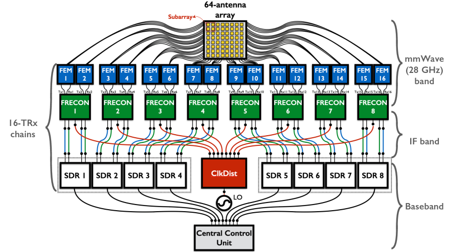
The analog subsystem includes a 64-element antenna array, a clock distribution module (ClkDist), frequency converters, and front-end modules for analog-domain beamforming. For reconfigurability and scalability of the testbed, we designed the FRECONs and FEMs in a modular way. Each module has a small number of TRx chains, i.e., two per FRECON and one per FEM. To up/down-convert between IF signal from/to the SDR and bands, we designed FRECON printed circuit boards that consist of up/down conversion mixers, filters, driver amplifiers, low-noise amplifiers, and SPDT switches. One FRECON is connected with one SDR. The main role of the FEM is to switch between four predefined beams, according to the control signal from the digital subsystem. The FEM, thus, contains a SP4T switch, and two FEMs are connected to the FRECON. The 64-element antenna array has 16 subarrays. Each subarray, consisting of four antenna elements, plugs in to one FEM where one antenna element in the subarray is selected for analog beamforming. In our testbed, the BS and UE, respectively, has a common local oscillator (LO) for up/down conversion between IF and bands. We employ a -LO (PLDRO-25500-10). To amplify and distribute the LO signal to multiple FRECONs, we design the ClkDist. Fig. 2 illustrates an architecture of 64-antenna/16-TRx hybrid beamforming testbed where the quantities of units belonging to each subsystem are also shown.
III Testbed Design and Implementation
To perform measurements in a variety of scenarios, sufficient gain of each TRx chain is imperative in designing a testbed. Also, for our proposed hybrid beamforming testbed, beam switchability is a key design feature. This section elaborates on the design of our massive MIMO testbed and its implementation.
III-A FRECON and FEM
MmWave systems are more sensitive to PA nonlinearities, compared to conventional systems below-. For the FRECON and FEM, we focused on an appropriate architecture design and component selection to reduce the PA nonlinearities.
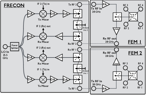
As mentioned in Sec. II, one FRECON has two TRx chains, and connects with two FEMs. A combined block diagram of FRECON and FEM is shown in Fig. 3(a). The FRECON contains the same eight DAs (HMC383LC4) but has different targets. Four DAs between an LO-input port and mixers is for amplifying the -LO signal, and the other four DAs for the transmit (Tx) signal. The mixers (HMC1063LP3E) are used for up/down-conversion between IF and bands, where an LO power of more than is required to operate it. That is the reason why a DA for amplifying the LO signal is needed for each mixer. The conversion gain of the mixer is around . To compensate this power loss and achieve high output power, the Tx chain is equipped with two consecutive DAs. On the other hand, each receive (Rx) chain contains an LNA (HMC1040LP3CE) to avoid compression. In the front-end of the FRECON, there are SPDT switches (ADRF5020) for TDD switching111We integrated two commercial antennas for future work, together with four radio frequency (RF) ports. Thus, there are a total of six SPDT switches to control all the RF inputs/outputs of FRECON..
The employment of FEM is to support testing of long-range communications, as well as beam-switching. As depicted in Fig. 3(a), one FEM contains an additional PA (MAAP-011246) and LNA, which have a high power gain. Also, a SPDT switch for TDD switching, and a SP4T switch for beam-selection are included. The SP4T switch engages with four RF ports, and performs switching or selecting by control signals from digital subsystem. For the beam-switching, the isolation between paths in the switches is crucial. The SPDT and SP4T switches, therefore, are designed so that they both have a high isolation222The manufactured SPDT and SP4T switches in the FEM yielded around and isolation, respectively. in mmWave frequencies. All the components, except the PA, were developed in-house.
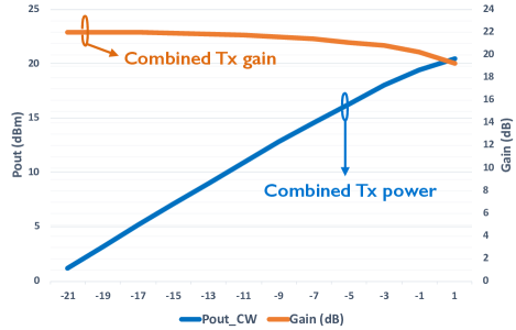
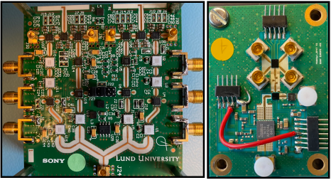
Photographs of the fabricated FRECON and FEM are shown in Fig. 3(b). Based on the measurements of each module, the Tx and Rx gains for the FRECON are around and , respectively. For the FEM, around and , respectively, is achieved. Fig. 4 shows a combined TRx gain of FRECON and FEM. The Tx gain in its linear region is around , as shown in Fig. 4(a). It delivers a 1-dB gain compression point (P1dB) of . The measured Rx gain is shown in Fig. 4(b). Its maximum gain is at . Also, the power consumption of the implemented FRECON and FEM is and , respectively.
III-B ClkDist
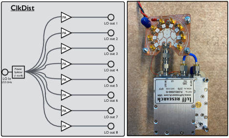
The block diagram of the ClkDist and its photograph are shown in Fig. 5. The ClkDist has 1 input and 8 output ports connecting with the LO and FRECONs, respectively. Since the 1-to-8 power splitter causes a power loss of more than , each path in the ClkDist is equipped with one DA (HMC383LC4) to meet the input-power requirement of mixers in FRECON. The power consumption of the fabricated ClkDist and the LO is and , respectively333LOs operating at mmWave frequencies is very sensitive to temperatures. Thus, we adopt a cooling fan to operate our -LO. Its power consumption is added in the LO’s power consumption..
III-C Antenna Array
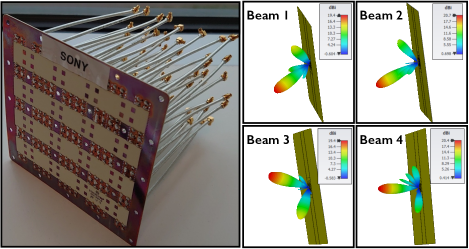
The planar 64-antenna array, consisting of 16 subarrays, is designed on a three-layer PCB using two stacked RO4350B substrates. Each subarray consists of patch antennas with a butler matrix, capable of forming four directional beams. The antenna-element spacing in the subarray is half a wavelength (), i.e., . The spacing between each subarray is , i.e., . The peak gain of single subarray and 16 subarrays, respectively, is and . Fig. 6 shows a photograph of the manufactured 64-antenna array and the beam patterns of 16 subarrays.
III-D TDD and Antenna Switching
Both FRECON and FEM have an interface, respectively, to receive DC () control signals from the digital subsystem, which are connected with the GPIO port. Since the GPIO port plugs in to an FPGA embedded in each SDR, the DC signal is controllable according to designed blocks in the digital subsystem. For the TDD and antenna switching, we implement control units in the digital subsystem, based on the frame structure and baseband functionalities of LuMaMi testbed [4]. Since the LuMaMi testbed operates in TDD mode, its control signal in the digital subsystem can be exploited to deliver to the analog subsystem. Using a regular beam sweeping in the Rx mode, channel estimation block computes the channel magnitudes, and returns the antenna index of the highest channel magnitude to the antenna-selection control unit. The system parameters for the developed testbed is summarized in Table I.
| Parameter | Value |
| Carrier frequency | |
| Intermediate frequency | |
| Sampling frequency | |
| Signal bandwidth | |
| FFT size | 2048 |
| Antenna-array configuration | 64 elements |
| Number of TRx chains | 16 |
| P1dB of each TRx chain | |
| Peak gain of 16 subarrays | |
IV Initial Results
This section provides initial results on the link-budget calculation through over-the-air (OTA) testing. Also, we perform an indoor uplink transmission with 16 TRx-chain BS and two single-antenna UEs to validate our testbed design.
For the link-budget calculation, we used one FRECON and one FEM for transmission and reception, respectively. To clarify the Tx and Rx power of an IF signal, a signal generator (E8257D) is connected to the FRECON input of the Tx side, and a spectrum analyzer (FSU50) to the FRECON output of the Rx side. Based on this setup, we calculate a measured FSPL for the distance between Tx and Rx antennas, and compare with its theoretical number. Effective isotropic radiated power (EIRP) is the hypothetical power radiated by a isotropic Tx antenna in the strongest direction and defined as
| (1) |
where is the Tx power (IF input), the effective Tx gain of FRECON and FEM, the cable loss in the Tx side, and the Tx antenna gain. Using the EIRP, the measured FSPL is
| (2) |
where is the Rx power (IF output), the effective Rx gain of FRECON and FEM, the cable loss in the Rx side, and the Rx antenna gain. The theoretical FSPL is
| (3) |
where is the carrier frequency, and is the speed of light. From (1)-(3), the link-budget calculation results are shown in Table II. It is observed that the measured FSPLs are quite close to the theoretical ones.
| (m) | (dB) | (dB) | Gap () |
| 7 | 68.3 | 71.3 | 3 |
| 8.7 | 70.2 | 72.9 | 2.7 |
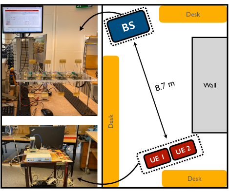
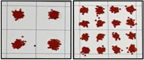
For the indoor test444The demo video is available at https://www.youtube.com/watch?v=rgoC6kTJnI8, we used a 16-TRx fully digital beamforming BS and two single-antenna UEs. The uplink transmission was performed in line-of-sight-like conditions. Fig. 7 shows the indoor measurement setup including the positions of the BS and UEs. The distance between the BS and the co-located UEs was . We observed very clear UL constellations. Fig. 8 shows captured constellations of the received uplink QPSK (UE 1) and 16-QAM (UE 2), where a zero-forcing equalizer is used at the BS.
V Conclusion
Both academia and industry have been making efforts in meeting 5G requirements. To support 5G, massive MIMO and mmWave have each shown strength and potential. Furthermore, it has been known that they are inseparably connected. Realizing mmWave massive MIMO in practice, however, is still an important issue that must be solved. As a viable solution, we have built the real-time massive MIMO testbed with a hybrid beamforming architecture. In this paper, we have provided an overview of our real-time mmWave () massive MIMO testbed, with a hybrid beamforming architecture based on beam-selection, and initial results through OTA testing.
Acknowledgment
The authors would like to thank Chris Clifton and Kamal K. Samanta at Sony Semiconductor, UK for useful discussions and for providing the FEM. In addition, this work is carried out within the Strategic Innovation Program “Smartare Elektroniksystem”, a joint venture of Vinnova, Formas and the Swedish Energy Agency (2018-01534).
References
- [1] T. Marzetta, “Noncooperative cellular wireless with unlimited numbers of base station antennas,” IEEE Trans. Wireless Comm., vol. 9, no. 11, pp. 3590–3600, Nov. 2010.
- [2] F. Rusek, D. Persson, B. K. Lau, E. G. Larsson, T. L. Marzetta, O. Edfors, and F. Tufvesson, “Scaling up MIMO: Opportunities and challenges with very large arrays,” IEEE Sig. Proc. Mag., vol. 30, no. 1, pp. 40–60, Jan. 2013.
- [3] C. Shepard, H. Yu, N. Anand, E. Li, Y. R. Marzetta, T., and L. Zhong, “Argos: Practical many-antenna base stations,” Proc. of ACM MobiCom, pp. 53–64, Aug. 2012.
- [4] S. Malkowsky, J. Vieira, L. Liu, P. Harris, K. Nieman, N. Kundargi, I. Wong, F. Tufvesson, V. Öwall, and O. Edfors, “The world first real-time testbed for massive MIMO: Design, implementation, and validation,” IEEE Access, vol. 5, pp. 9073–9088, 2017.
- [5] T. Rappaport, S. Sun, R. Mayzus, H. Zhao, Y. Azar, K. Wang, G. N. Wong, J. K. Schulz, M. Samimi, and F. Gutierrez, “Millimeter wave mobile communications for 5G cellular: It will work!” IEEE Access, vol. 1, pp. 335–349, 2013.
- [6] W. Roh, J. Y. Seol, J. Park, B. Lee, J. Lee, Y. Kim, J. Cho, K. Cheun, and F. Aryanfar, “Millimeter-wave beamforming as an enabling technology for 5G cellular communications: Theoretical feasibility and prototype results,” IEEE Comm. Mag., vol. 52, no. 2, pp. 106–113, Feb. 2014.
- [7] S. Han, I. Chih-Lin, Z. Xu, and C. Rowell, “Large-scale antenna systems with hybrid analog and digital beamforming for millimeter wave 5G,” IEEE Comm. Mag., vol. 53, no. 1, pp. 186–194, Jan. 2015.
- [8] M. Chung, L. Liu, O. Edfors, and F. Tufvesson, “Millimeter-wave massive MIMO testbed with hybrid beamforming,” Proc. IEEE Wireless Comm. and Net. Conf. Workshops (WCNCW), pp. 1–2, Apr. 2020.
- [9] M. Shafi, J. Zhang, H. Tataria, A. F. Molisch, S. Sun, T. S. Rappaport, F. Tufvesson, S. Wu, and K. Kitao, “Microwave vs. millimeter-wave propagation channels: Key differences and impact on 5G cellular systems,” IEEE Comm. Mag., vol. 56, no. 12, pp. 14–20, Dec. 2018.
- [10] M. Chung, L. Liu, and O. Edfors, “Phase-noise compensation for OFDM systems exploiting coherence bandwidth: Modeling, algorithms, and analysis,” Jul. 2020, [Online] Available: https://arxiv.org/pdf/2007.09628.pdf.
- [11] M. Chung, H. Prabhu, F. Sheikh, O. Edfors, and L. Liu, “Low-complexity fully-digital phase noise suppression for millimeter-wave systems,” Proc. IEEE Int. Symp. on Circ. and Sys. (ISCAS), pp. 1–5, Oct. 2020.
- MIMO
- multiple-input multiple-out
- CSI
- channel state information
- mmWave
- millimeter-wave
- cmmWave
- Millimeter-wave
- 5G
- fifth-generation
- MU
- multi-user
- UE
- user equipment
- SNR
- signal-to-noise ratio
- TRx
- transceiver
- Tx
- transmit
- Rx
- receive
- BS
- base station
- OFDM
- orthogonal frequency division multiplexing
- TDD
- time-division duplex
- LuMaMi
- Lund University massive MIMO
- SDR
- software-defined radio
- IF
- intermediate frequency
- GPIO
- general-purpose input/output
- ClkDist
- clock distribution module
- FRECON
- frequency converter
- FEM
- front-end module
- LO
- local oscillator
- PCB
- printed circuit board
- DA
- driver amplifier
- PA
- power amplifier
- LNA
- low-noise amplifier
- RF
- radio frequency
- OTA
- over-the-air
- FSPL
- free-space path loss
- EIRP
- Effective isotropic radiated power
- LoS
- line-of-sight
- MMSE
- Minimum Mean Square Error
- MU-MIMO
- Multi-User MIMO
- MS
- Mobile Station
- DPC
- Dirty Paper Coding
- ZF
- Zero-Forcing
- MF
- Matched Filter
- VPU
- vector processing unit
- MSB
- Most Significant Bit
- WL
- Word Length
- BER
- Bit Error Rate
- FF
- Folding Factor
- FIFO
- First-In-First-Out
- MUI
- Multi-User Interference
- DNS
- Diagonal Neumann Series
- TNS
- Tri-diagonal Neumann series
- MAC
- Multiply-Accumulate
- CE
- constant envelope
- PE
- Processing Element
- PAR
- Peak-to-Average Ratio
- IDFT
- Inverse Discrete Fourier Transform
- CCDF
- Complementary Cumulative Distribution Function
- OBR
- Out-of-Band (ratio) Power
- SINR
- Signal-to-interference-plus-noise ratio
- SDNR
- Signal-to-distortion-plus-noise ratio
- IBO
- Input-Back-off
- OBO
- Output-Back-off
- ISI
- Inter-Symbol Interference
- MUI
- Multi-user interference
- LUT
- Look-Up-Table