MethodsReferences
Magneto-active elastic shells with tunable buckling strength
Shell buckling is central in many biological structures and advanced functional materials, even if, traditionally, this elastic instability has been regarded as a catastrophic phenomenon to be avoided for engineering structures. Either way, predicting critical buckling conditions remains a long-standing challenge. The subcritical nature of shell buckling imparts extreme sensitivity to material and geometric imperfections. Consequently, measured critical loads are inevitably lower than classic theoretical predictions. Here, we present a robust mechanism to dynamically tune the buckling strength of shells, exploiting the coupling between mechanics and magnetism. Our experiments on pressurized spherical shells made of a magnetorheological elastomer demonstrate the tunability of their buckling pressure via magnetic actuation. We develop a theoretical model for thin magnetic elastic shells, which rationalizes the underlying mechanism, in excellent agreement with experiments. A dimensionless magneto-elastic buckling number is recognized as the key governing parameter, combining the geometrical, mechanical, and magnetic properties of the system.
Shells are curved thin structures that can withstand extreme loading conditions due to the interplay between bending and stretching deformation 1, 2 through the so-called ‘shell effect’ 3. Thin shells are an ubiquitous structural element in engineering 4 and also widely observed in nature across length scales, from viruses 5, and capsules 6, 7, 8, to pollen grains 9, and plants 10. While curvature is the key ingredient underlying the excellent mechanical performance of shells, it is also responsible for the catastrophic (subcritical) nature of their elastic instabilities 11. Consequently, shells are high sensitivity to imperfections 12, 1, 13, 14. For over a century, the pressure buckling of a spherical shell has been a long-standing canonical problem of elastic (in)stability 1, 2. When the in-out pressure differential across a shell exceeds a threshold value, the shell loses its load-carrying capacity 1. The ensuing collapse is unpredictable, occurring at loads that are significantly lower than classic theoretical predictions 14. Consequently, measuring and predicting the critical buckling pressure has proven to be nontrivial due to the high imperfection sensitivity.
In 1915, Zoelly 15 derived the theoretical prediction for the critical buckling pressure of a perfect spherical shell, of radius and thickness , loaded under a uniform pressure :
| (1) |
where and are the Young’s modulus and Poisson’s ratio of the material, respectively. Notwithstanding this classic result, given the high imperfection sensitivity, buckling pressures measured in experiments, , have long been found 12, 13, 14, 1 to be much lower than the prediction from Eq. (1). This discrepancy generated a long debate in the shell mechanics community that lasted for nearly four decades until the disagreement between theory and experiments was finally attributed to imperfections 16. Given this intrinsic mismatch, it became standard to define an empirical quantity, the so-called knockdown factor,
| (2) |
which is always smaller than unity, spreading a wide range 14, 17: .
In engineering, significant efforts have focused on improving predictions for the knockdown factor and understanding how it is affected by imperfections 12, 13, 14, 1. A breakthrough came only recently, from experiments, when the combination of a rapid prototyping technique for spherical shells 18 and its adaptation to seed precisely designed defects led to a quantitative relationship between the knockdown factor and defect geometry 17. This study demonstrated that if imperfections can be measured precisely, then the knockdown factor can be precisely predicted using an appropriate shell theory 19, 20, 21, 22, 23, 24, 25, thus opening the door for less conservative designs of shell structures. In parallel, nondestructive probing methods have recently been proposed to experimentally access the stability landscape of shells 26, 27, 28, while accepting the inevitable presence of multiple imperfections to set the knockdown factor. Furthermore, bilayer shells undergoing differential swelling were recently shown to have a varying knockdown factor during a transient, demonstrating how the knockdown factor can be modified post-fabrication, albeit not reversibly on-demand 29. Still, to date, the knockdown factor is regarded as an intrinsic structural property dictated by imperfections imparted during fabrication or encoded at the design stage.
Here, we propose a robust mechanism to dynamically tune the buckling strength of shells (i.e., their knockdown factor), by coupling elastic deformation and magnetic actuation, to provide active control and liberate the predestination of imperfections. Our framework leverages recent advances in magneto-elastic mechanical systems – including shape-programmable materials 30, 31, 32, 33, biomedical devices 34, and soft robots 35, 36, 36, 37 –, which we augment in the context of shell mechanics. Specifically, we manufacture spherical shells made of a hard-magnetic elastomer (hereon referred to as magnetic shells) and characterize their critical buckling pressure under an applied magnetic field. We demonstrate that the knockdown factor can be modified externally by adjusting the magnitude and polarity of the field. To rationalize our results, we develop a magnetic shell theory, providing a physical interpretation of the interplay between shell mechanics and magnetic fields. Furthermore, we uncover the magneto-elastic buckling number (a dimensionless quantity that combines the magnetic, elastic, and geometrical properties), which acts as the single governing parameter of the system.
Experiments on tuning the knockdown factor of pressurized magnetic shells
In our experiments, we position a hemispherical shell of radius, mm, and thickness, m, in between a set of Helmholtz coils (Fig. 1a,b). These two coils impose a steady, uniaxial and uniform magnetic field (flux density vector ) on the shell, perpendicularly to its equatorial plane (see Methods and Supplementary Notes S1 and S2 for details). The shell is made of a magnetorheological elastomer (MRE), a composite of hard-magnetic NdPrFeB particles (volume fraction ) and vinylpolysiloxane (VPS) polymer (see Methods). The full 3D configuration and the corresponding cross-section profile of the shell are visualized through X-ray micro-computed tomography (CT, 100 Scanco Medical AG), a representative example of which is presented in Fig. 1c. To measure the buckling strength, we depressurize the shell using a pneumatic-loading system under imposed-volume conditions and measure the associated pressure sustained by the shell (Methods and Supplementary Note S2). Figure 1d presents the load-carrying behavior of the shell, characterized by the pressure () as a function of the volume change (), both of which are normalized, respectively, by the classic buckling prediction, , and the corresponding volume change immediately prior to buckling 19, 20, . The onset of buckling corresponds to the maximum of each curve, , and the accompanying pressure drop indicates the loss of load-carrying capacity of the shell.
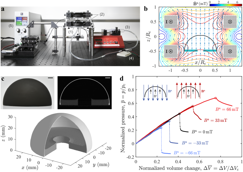
In the absence of magnetic field (mT), the representative shell shown in Fig. 1c buckles at the dimensionless pressure level of . This value is far below the classical prediction of 1 (), the reason being that we intentionally seed a precisely engineered dimple-like defect at the pole during manufacturing (Methods and Supplementary Note S1), so as to consider the influence of imperfections in a controllable manner. Hence, the geometry of the shell deviates slightly from a perfect hemisphere by an amplitude of over the region of polar angle . The half angular width of the defect is then measured by , usually rescaled as 17, 19, 21, 25. For this test shell, the defect geometry is characterized as and () using an optical profilometer (Methods and Supplementary Note S1). Although the introduced defect is too small to be seen with the naked eye, the buckling strength of the shell is dramatically reduced, by more than a half due to the high sensitivity to imperfections 1, 19, 17.
We proceed by focusing on the effect of the magnetic field on the buckling instability. The magnetized shell possesses a residual flux density of (mT, see Methods and Supplementary Note S1), and is responsive to an external magnetic field, with a significant modification of the buckling pressure (Fig. 1d) compared to the no-field case. When the field vector is parallel to the axis of magnetization (i.e., and are in the same direction), we observe an increase of the critical loads by and under the flux densities mT and mT, respectively. Meanwhile, the accompanying pressure drop at the onset of buckling is gradually reduced, eventually disappearing for mT. Therefore, the shell is strengthened by the applied field, and the buckling event becomes less catastrophic. By contrast, for the opposite field polarity (i.e., and are in opposite directions), the shell is weakened; the critical load decreases with a consequent more abrupt pressure drop past the buckling event (mT in Fig. 1d). These findings demonstrate that the intrinsic buckling strength of a magnetically active shell can be modified (increased or decreased), under an external magnetic field, on-demand.
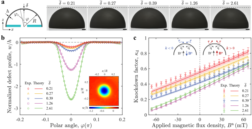
To further explore the effect of magnetism on the buckling strength of pressurized spherical shells, we test shells with different defect geometries, over a range of external flux densities. As shown in the photographs of the specimens in Fig. 2a, the defect amplitudes are varied as during manufacturing (Methods and Supplementary Note S1). The axisymmetric defect profiles, , are presented in Fig. 2b, defined as the radial deviation of the measured shell profile from a perfect hemisphere. Figure 2c presents the corresponding knockdown factor measurements, , as a function of the external flux density, . Naturally, due to imperfection sensitivity, the shells exhibit distinct knockdown factors for different values of . However, in the presence of the magnetic field, we consistently observe an increasing or decreasing knockdown factor over the explored range of . Within the range of accessible in our experiments, can be changed up to approximately , with respect to the no-field case. These experimental results demonstrate that the knockdown factor of a shell can be dynamically tuned, as an extrinsic quantity, by adjusting the polarity and strength of the applied magnetic field, via a robust mechanism that is insensitive to imperfections.
Theory of axisymmetric hard-magnetic shells
To rationalize the experimental results presented above, we develop a theoretical model that predicts the response of hard-magnetic axisymmetric thin shells under a combination of mechanical and magnetic loading. We consider the Helmholtz free energy of ideal hard-magnetic soft materials 35, 38, comprising an elastic energy term (related to material deformation) and a magnetic energy term (describing the work to align the residual magnetic vector along the external magnetic field). The shell model is developed by reducing this three-dimensional energy to the 1D profile curve of the middle surface of the shell (detailed derivation provided in Supplementary Note S3). The dimensional reduction of the Kirchhoff-Saint Venant elastic energy 39, valid for small strains and large displacements, with the potential of live pressure was reported recently 40. In the present study, we focus on the magnetic energy term, which, for 3D scale-free materials, is written as 41, 35, 38 , where is the deformation gradient 39. We describe the axisymmetric shell profile by the coordinates , being the radial coordinate in the plane perpendicular to the axis of axisymmetry (). Accented quantities (e.g., ) refer to the undeformed configuration of the shell. The reduced D magnetic energy, normalized by , can be derived as (Supplementary Note S3)
| (3) |
where is the area measure, and is a dimensionless function that depends on the initial and deformed configurations of the shell. From Eq. (3), we identify a magneto-elastic parameter
| (4) |
which represents the intrinsic magneto-elastic coupling of the system. Equilibrium equations can be generated by minimizing the total energy for all the possible displacements of the shell, which were solved via the Newton-Raphson method (see Methods and Supplementary Note S3.1.4) 40.
It is important to highlight that, in our simulations of the 1D model presented above, we use the geometric and physical parameters of the system measured in experiments (see Methods), without any fitting parameters. The defect profile in the region is described analytically by (Fig. 2b), derived based on a simple plate model (Supplementary Note S1). Excellent agreement is found between theory and experiments (Fig. 2c). The variation of the knockdown factor for shells with different defect geometries under the magnetic field is accurately predicted by our shell model, which is, therefore, able to describe the intricate coupling between elasticity, magnetism, and the nonlinear mechanics of thin shells.
Physical interpretation of the reduced magnetic energy
Even though our theoretical model can predict the buckling strength of shells, the reduced magnetic energy is highly nonlinear, and the mechanism underlying the change of knockdown factors still needs to be clarified. Therefore, we proceed to expand the integrand of the reduced magnetic energy density in Eq. (3), , up to second order in the displacement field (Supplementary Note S3). By examining the role of each term in the buckling instability, we conclude that only the following second-order term dominates the buckling of the shell,
| (5) |
where is the rotation vector of a material fiber of the shell 2, 42, and can be interpreted as a distributed (dimensionless) torque applied by the external magnetic field. This torque is a linear function of the shell rotation with a deformation-independent pre-factor , which we can interpret as the (dimensionless) stiffness of distributed rotational springs, where .
Under pressure loading, material fibers tend to rotate, thereby increasing the magnetic torque (Supplementary Note S3). Whether the torque reacts to restore the undeformed orientation of the material fibers or to rotate them further away from the initial orientation, depends on the sign of the equivalent stiffness (insects in Fig. 2c). When and are in the same direction, the stiffness is positive, thus ensuring that is opposite to , thereby counteracting buckling. As a result, we observe the strengthening of shells with increasing critical loads (cases with in Fig. 2c). Conversely, when and and in opposite directions, the negative stiffness () leads to a torque that acts to increase the rotation . Indeed, in this regime, buckling occurs at lower pressure levels (cases with in Fig. 2c).
Scaling analysis of the change of knockdown factor
With a physical interpretation of the magnetic energy for shells at hand, we now employ scaling arguments to more clearly rationalize how the knockdown factor is modified by the magnetic field for different radius-to-thickness ratios.
Since the magnetic energy interacts with the live pressure potential to alter the knockdown factor, we balance the two energy terms. The dimensionless magnetic energy can be shown to scale as , while the change of knockdown factor with respect to the non-magnetic case, , scales as (Supplementary Note S3). By balancing the scalings for the potential of , that is , and the magnetic energy , we find , translating into
| (6) |
From Eq. (6), we define the magneto-elastic buckling number,
| (7) |
which governs the knockdown factor under combined pressure and magnetic loading of magnetic shells. The scaling provides a scale-invariant description of how the magnetic field modifies the buckling pressure for shells with different radius-to-thickness ratios.
Robustness of the mechanism to geometric imperfections
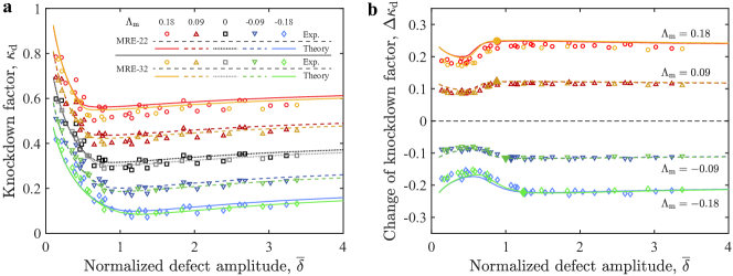
We set out to investigate the role of imperfections in the buckling of magnetic shells, which we now address with a more systematic parametric exploration. We fabricate shells over a wide range of the defect amplitude () and measure the corresponding knockdown factors, , from buckling tests. In parallel, we run 1D simulations for the same material and geometrical properties. Figure 3a illustrates the relationship between and at different levels of external flux density, included in the magneto-elastic buckling number, , of Eq. (7). The signature of imperfection sensitivity is still observed in the presence of the magnetic field: decreases dramatically when the defect amplitude increases in the regime of relatively small defects (). Surprisingly, the results of the change in knockdown factor under the applied magnetic field () presented in Fig. 3b are significantly less sensitive to defects; becomes approximately constant for . This finding suggests that the magnetic interaction between the shell and the external field is nearly unaffected by the intrinsic imperfection sensitivity, ensuring a robust tuning of the knockdown factor.
Moreover, the results in Fig. 3a,b include data for two sets of shells with a different combination of material and geometric properties (MPa, for MRE-22 shells and MPa, for MRE-32 shells; see Methods). Still, the and data collapse for these two sets, given that the value of is the same for both. This collapse supports as the governing parameter, combining the mechanical, magnetic, and geometrical properties of the system. Throughout the analysis, the theory is in excellent agreement with experiments.
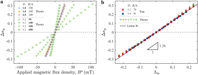
A robust way to quantify the effect of the magnetic field on the change in knockdown factor is to focus on the plateau in Fig. 3b, , defined as the average of over the extent of the plateau-like region. Figure 4a (open symbols) shows predictions from our shell model for versus the external flux density, , for shells with different radius-to-thickness ratios and defect widths. While the radius-to-thickness ratio strongly influences the change in knockdown factor, the defect width has little effect on it (Supplementary Note 4). In Fig. 4b, we plot the raw data of Fig. 4a as a function of the magneto-elastic buckling number , finding that the different results for shells with different geometries fall onto a master curve. This collapse demonstrates that the plateau change of knockdown factor is governed by the single parameter , independently of the geometry of the defect. The superposition of experimental results on the theoretical predictions further validates this collapse. Moreover, consistently with the scaling in Eq. (6), a linear relationship is found between and , with a slope of obtained via linear fitting. This master curve serves as a concrete design guideline for magnetic shells, summarizing the effect of the magnetic field in tuning the buckling strength of pressurized spherical shells with different material and geometrical properties.
In closing, we have shown that the buckling strength of shells can be dynamically tuned by exploiting the interplay between mechanics and magnetism. The proposed mechanism represents a robust way to gain control on a property of thin shells that has long been regarded as intrinsic, the knockdown factor. By performing precision experiments on hard-magnetic elastomeric shells and developing a theoretical model, we unveiled the essential feature at the base of the mechanism, a distributed torque induced by the magnetic field throughout the shell. Moreover, we showed that a dimensionless quantity, the magneto-elastic buckling number, emerges as the key governing parameter, summarizing the geometrical, mechanical, and magnetic properties of the system. We envision that our mechanism can also be used to gain control on the structural life of a shell, by tuning the magnetic field as critical conditions approach. More generally, we believe that the approach of coupling mechanical deformation and magnetic fields, already successfully applied for beams 32, 38, 36, 43, films 33, and soft materials 35, and employed here to tune the knockdown factor of shells, can be extended to modify the instabilities of other structures such as rods, plates, and non-axisymmetric shells 30, 31, for which research efforts are currently ongoing. We anticipate that magnetic structures with predictable and tunable buckling behavior will enrich the design of advanced materials with new functionalities.
Methods
Preparation of the MRE material. Our experimental samples were fabricated using a MRE material composed of a mixture of hard-magnetic NdPrFeB particles (average size of m, MQFP-15-7-20065-089, Magnequench) and Vinylpolysiloxane (VPS, Elite Double, Zhermack), a silicone-based polymer. MREs made of VPS Elite Double 22 or VPS Elite Double 32 are referenced throughout the text as MRE-22 or MRE-32, respectively. We prepared the MRE with the following steps. First, the initially non-magnetized NdPrFeB particles were mixed with the liquid VPS base (1:1 mass ratio) using a centrifugal mixer (ARE-250, Thinky Corporation); for s at rpm (clockwise), and another s at rpm (counterclockwise). Secondly, the solution was degassed in a vacuum chamber (absolute pressure below mbar), and then cooled down to room temperature (C) to avoid any changes of viscosity due to thermal disturbances from the previous steps. Thirdly, VPS catalyst was added to the mixture, with a ratio of 1:1 in weight to the VPS base. After another mixing step for s at rpm (clockwise) followed by s at rpm (counterclockwise), the final mixture was ready for sample fabrication. The final mass concentrations of NdPrFeB particles and VPS polymer were and , respectively. Pouring of the liquid MRE mixture onto the mold during shell fabrication (see below) was done after a set waiting time (s for MRE-22 and s for MRE-32), so as to increase the viscosity to the desired value. After the above preparation steps, the curing of the polymer mixture occurred in approximately 20 min at room temperature.
Physical properties of the MRE. The densities of MRE-22 and MRE-32 were measured using a pycnometer to be and , respectively. The density of the NdPrFeB particles is (provided by the supplier). Under the concentrations of the prepared mixture, the volume fraction of NdPrFeB particles was calculated to be 7.05% for MRE-22 and 7.14% for MRE-32. When saturated, the effective residual flux density of our MRE, , was assumed to be the volume-average of the total residual flux density of individual NdPrFeB particles (T, as reported by the supplier). Given the chosen volume fraction, mT for MRE-22 and mT for MRE-32. The Young’s moduli of MRE-22 and MRE-32 were measured to be , and , respectively, using a combination of cantilever and tensile tests.
Fabrication of the magneto-active shell specimens. Our shells were fabricated by coating the underside of a flexible negative spherical mold (radius mm) with liquid MRE; see the schematic in Supplementary Fig. S1 and Supplementary Note S1 for details. Whereas our technique was inspired by previous work 18, 17, our molds also contained a soft spot (thin circular region) at the pole to produce a precisely-engineered defect. With the negative spherical surface of the mold facing down, the gravity-driven viscous flow of the polymer yielded a thin layer of MRE on the mold. Before the MRE fully cured (min after pouring), the mold was depressurized from within using a syringe pump. As a result, the soft spot of the mold deformed to produce an axisymmetric geometric imperfection at the pole of the shell. This defect becomes ‘frozen’ in the shell upon curing. The amplitude of the defect can be systematically varied by adjusting the pressure imposed on the mold during curing (Supplementary Fig. S2). The width of the defect can be varied by changing the pillar used in mold manufacture with a different radius (Supplementary Note S1). The amplitude and width of the defect can be set independently. To make the shell magnetically active, we saturated the NdPrFeB particles, already in the solidified MRE, using an applied uniaxial magnetic field (T, perpendicular to the equatorial plane) generated by an impulse magnetizer (IM-K-010020-A, Magnet-Physik Dr. Steingroever GmbH).
Geometry of the shells. The radius of the shells (mm) is set by the mold used during fabrication. Their thickness was characterized using a microscope (VHX-5000, Keyence Corporation) after cutting off narrow strips () near the pole. The average measured thickness was and for the MRE-22 and the MRE-32 shells, respectively. Hence, the corresponding radius-to-thickness ratios were and . The 3D profile of the outer surface of each fabricated imperfect shell was characterized using an optical profilometer (VR-3200, Keyence Corporation). The geometry of the defect was computed as the radial distance between the measured profile and the corresponding best-fit spherical surface. Specifically, the amplitude, , and half angular width, , of the defect were determined by fitting the analytical description, , to the experimental measurements (additional details provided in Supplementary Note S1). The ranges of geometric parameters for our specimens are as follows: and () for the MRE-22 shells; and and () for the MRE-32 shells.
Generation of the magnetic field. A uniaxial uniform magnetic field was generated in the central region of two identical customized multi-turn circular coils (square cross-section, inner diameter mm, outer diameter mm, and height mm), configured in the Helmholtz configuration. The coils were set concentrically, with a centre-to-centre axial distance of mm, and connected in series, powered by a DC power supply providing a maximum current/power of A/kW (EA-PSI 9200-25 T, EA-Elektro-Automatik GmbH). The flux density of the magnetic field was varied in the range by adjusting the current output of the power supply, from A to A. The flux density was measured using a Teslameter (FH 55, Magnet-Physik Dr. Steingroever GmbH), along both the axial and radial directions. In parallel to the experiments, we simulated the generated field using the Magnetic Fields interface embedded in the commercial package COMSOL Multiphysics (v. 5.2, COMSOL Inc.), based on Ampère’s Law (see Supplementary Note S2 for details). Excellent agreement was found between experiments and simulations (Supplementary Fig. S3).
Buckling tests. To quantify the critical buckling conditions of our magnetic shells, we positioned each shell in between the Helmholtz coils under a steady magnetic field, and then depressurized it under prescribed volume conditions by a pneumatic loading system (see Supplementary Note S2 for details). The applied pressure was monitored by a pressure sensor (785-HSCDRRN002NDAA5, Honeywell International Inc.). The level of depressurization was increased, under a steady magnetic field, until the shell buckled. The critical buckling pressure was defined as the maximum value of the loading curve (pressure vs. imposed volume change).
Theory and numerics. The reduced 1D energy , representing the sum of the elastic and magnetic energies of the system, together with the potential of the live pressure, is obtained by means of dimensional reduction (see Supplementary Note S3 for details). Equilibrium equations are generated by minimizing the total energy for all possible displacements of the shell, and solved via the Newton-Raphson method using the commercial package COMSOL Multiphysics (v. 5.2, COMSOL Inc.). Details of the implementation of our numerical procedure are provided in Ref. 40.
Acknowledgements
We thank Selman Sakar and Lucio Pancaldi-Giubbini for providing the coils. We acknowledge Benjamin Rahm for help with preliminary experiments. A.A. is grateful to the support from the Federal Commission for Scholarships for Foreign Students (FCS) through Swiss Government Excellence Scholarship (Grant No. 2019.0619).
This is a preprint of an article published in Nature Communications. The final authenticated version is available online at: \urlhttps://doi.org/10.1038/s41467-021-22776-y.
Author contributions
D.Y. and P.M.R. conceived the project. D.Y., L.C. and A.A. performed experiments and analyzed data. M.P. developed the theoretical model and performed the scaling analysis. M.P. and D.Y. performed simulations and analyzed data. P.M.R. supervised the research. D.Y., M.P., A.A. and P.M.R. wrote the paper.
Competing interests
The authors declare no competing interests.
Additional information
Correspondence and requests for materials should be addressed to P.M.R.
References
- 1 Koiter, W. T. The nonlinear buckling behavior of a complete spherical shell under uniform external pressure, parts i, ii, iii & iv. Proc. Kon. Ned. Ak. Wet. B72, 40–123 (1969).
- 2 Niordson, F. I. Shell Theory. North-Holland Series in Applied Mathematics and Mechanics (Elsevier Science, 1985).
- 3 Hutchinson, J. W. EML Webinar overview: New developments in shell stability. Extreme Mech. Lett. 39, 100805 (2020).
- 4 Hilburger, M. W. Developing the next generation shell buckling design factors and technologies. In 53rd AIAA/ASME/ASCE/AHS/ASC Structures, Structural Dynamics and Materials Conference, Structures, Structural Dynamics, and Materials and Co-located Conferences (American Institute of Aeronautics and Astronautics, Honolulu, HI, 2012).
- 5 Lidmar, J., Mirny, L. & Nelson, D. R. Virus shapes and buckling transitions in spherical shells. Phys. Rev. E 68, 051910 (2003).
- 6 Sacanna, S., Irvine, W., Chaikin, P. & Pine, D. Lock and key colloids. Nature 464, 575–578 (2010).
- 7 Datta, S. S. et al. Delayed buckling and guided folding of inhomogeneous capsules. Phys. Rev. Lett. 109, 134302 (2012).
- 8 Vian, A. & Amstad, E. Mechano-responsive microcapsules with uniform thin shells. Soft Matter 15, 1290–1296 (2019).
- 9 Katifori, E., Alben, S., Cerda, E., Nelson, D. R. & Dumais, J. Foldable structures and the natural design of pollen grains. Proc. Natl. Acad. Sci. U.S.A. 107, 7635–7639 (2010).
- 10 Forterre, Y., Skotheim, J. M., Dumais, J. & Mahadevan, L. How the Venus flytrap snaps. Nature 433, 421–425 (2005).
- 11 Misbah, C. Complex Dynamics and Morphogenesis (Springer, 2016).
- 12 Tsien, H.-S. A theory for the buckling of thin shells. Journal of the Aeronautical Sciences 9, 373–384 (1942).
- 13 Hutchinson, J. W. Imperfection sensitivity of externally pressurized spherical shells. J. Appl. Mech. 34, 49–55 (1967).
- 14 Carlson, R. L., Sendelbeck, R. L. & Hoff, N. J. Experimental studies of the buckling of complete spherical shells. Exp. Mech. 7, 281–288 (1967).
- 15 Zoelly, R. Ueber ein knickungsproblem an der kugelschale. Ph.D. thesis, ETH Zürich, Zürich, Switzerland (1915).
- 16 Elishakoff, I. Resolution of the Twentieth Century Conundrum in Elastic Stability (World Scientific Publishing, Singapore, 2014).
- 17 Lee, A., López Jiménez, F., Marthelot, J., Hutchinson, J. W. & Reis, P. M. The geometric role of precisely engineered imperfections on the critical buckling load of spherical elastic shells. J. Appl. Mech. 83, 111005 (2016).
- 18 Lee, A. et al. Fabrication of slender elastic shells by the coating of curved surfaces. Nat. Commun. 7, 11155 (2016).
- 19 Hutchinson, J. W. Buckling of spherical shells revisited. Proc. Math. Phys. Eng. Sci. 472, 20160577 (2016).
- 20 Hutchinson, J. W. & Thompson, J. M. T. Nonlinear buckling behaviour of spherical shells: barriers and symmetry-breaking dimples. Philos. Trans. Royal Soc. A 375, 20160154 (2017).
- 21 López Jiménez, F., Marthelot, J., Lee, A., Hutchinson, J. W. & Reis, P. M. Technical brief: Knockdown factor for the buckling of spherical shells containing large-amplitude geometric defects. J. Appl. Mech 84, 034501 (2017).
- 22 Ning, X. & Pellegrino, S. Searching for imperfection insensitive externally pressurized near-spherical thin shells. J. Mech. Phys. Solids 120, 49–67 (2018).
- 23 Gerasimidis, S., Virot, E., Hutchinson, J. W. & Rubinstein, S. M. On establishing buckling knockdowns for imperfection-sensitive shell structures. Journal of Applied Mechanics 85, 091010 (2018).
- 24 Sieber, J., Hutchinson, J. W. & Thompson, J. M. T. Buckling thresholds for pre-loaded spherical shells subject to localized blasts. J. Appl. Mech 87, 031013 (2020).
- 25 Yan, D., Pezzulla, M. & Reis, P. M. Buckling of pressurized spherical shells containing a through-thickness defect. J. Mech. Phys. Solids 138, 103923 (2020).
- 26 Virot, E., Kreilos, T., Schneider, T. M. & Rubinstein, S. M. Stability landscape of shell buckling. Phys. Rev. Lett. 119, 224101 (2017).
- 27 Marthelot, J., López Jiménez, F., Lee, A., Hutchinson, J. W. & Reis, P. M. Buckling of a pressurized hemispherical shell subjected to a probing force. J. Appl. Mech. 84, 121005 (2017).
- 28 Thompson, J. M. T., Hutchinson, J. W. & Sieber, J. Probing shells against buckling: a nondestructive technique for laboratory testing. Int. J. Bifurcat. Chaos 27, 1730048 (2017).
- 29 Lee, A., Yan, D., Pezzulla, M., Holmes, D. P. & Reis, P. M. Evolution of critical buckling conditions in imperfect bilayer shells through residual swelling. Soft Matter 6134–6144 (2019).
- 30 Loukaides, E. G., Smoukov, S. K. & Seffen, K. A. Magnetic actuation and transition shapes of a bistable spherical cap. Int. J. Smart Nano. Mater. 5, 270–282 (2014).
- 31 Seffen, K. A. & Vidoli, S. Eversion of bistable shells under magnetic actuation: a model of nonlinear shapes. Smart Mater. Struct. 25, 065010 (2016).
- 32 Lum, G. Z. et al. Shape-programmable magnetic soft matter. Proc. Natl. Acad. Sci. U.S.A. 113, E6007–E6015 (2016).
- 33 Psarra, E., Bodelot, L. & Danas, K. Wrinkling to crinkling transitions and curvature localization in a magnetoelastic film bonded to a non-magnetic substrate. J. Mech. Phys. Solids 133, 103734 (2019).
- 34 Hu, W., Lum, G. Z., Mastrangeli, M. & Sitti, M. Small-scale soft-bodied robot with multimodal locomotion. Nature 554, 81–85 (2018).
- 35 Kim, Y., Yuk, H., Zhao, R., Chester, S. A. & Zhao, X. Printing ferromagnetic domains for untethered fast-transforming soft materials. Nature 558, 274 (2018).
- 36 Kim, Y., Parada, G. A., Liu, S. & Zhao, X. Ferromagnetic soft continuum robots. Sci. Robot. 4, eaax7329 (2019).
- 37 Gu, H. et al. Magnetic cilia carpets with programmable metachronal waves. Nat. Commun. 11, 2637 (2020).
- 38 Zhao, R., Kim, Y., Chester, S. A., Sharma, P. & Zhao, X. Mechanics of hard-magnetic soft materials. J. Mech. Phys. Solids 124, 244–263 (2019).
- 39 Gurtin, M. E., Fried, E. & Anand, L. The Mechanics and Thermodynamics of Continua (Cambridge University Press, 2010).
- 40 Pezzulla, M. & Reis, P. M. A weak form implementation of nonlinear axisymmetric shell equations with examples. J. Appl. Mech. 84, 034501 (2019).
- 41 Bertotti, G. Hysteresis in Magnetism: for Physicists, Materials Scientists, and Engineers (Academic Press, 1998).
- 42 Pezzulla, M., Stoop, N., Steranka, M. P., Bade, A. J. & Holmes, D. P. Curvature-induced instabilities of shells. Phys. Rev. Lett. 120, 048002 (2018).
- 43 Wang, L., Kim, Y., Guo, C. F. & Zhao, X. Hard-magnetic elastica. J. Mech. Phys. Solids 142, 104045 (2020).