Design of simple stellarator using tilted toroidal field coils
Abstract
This paper deals with the design of the stellarator field with the simple coil set. In order to realize the stellarator field by the simple coil set, the tilted toroidal field coil uses for creating the rotational transform. Sixteen tilted TF coils create the small radial field and large vertical field. With reducing the vertical field of the tilted toroidal field coil by the axisymmetric poloidal field coil, the stellarator field can be made. The formation of clear and nested flux surfaces is confirmed, and the rotational transform is proportional to the tilting angle of the toroidal field coil. Main components of the magnetic field for the simple stellarator in this paper are the large mirror ripple and small helical ripple. This is a similar property to the quasi-isodynamic configuration like the Wendelstein 7-X stellarator. The collisionless orbit for the proton is studied. For a moderate tilting angle of the toroidal field coil, the confinement of the passing and trapped particles improves.
I Introduction
The tokamak is the first candidate of the fusion reactor. However, although the tokamak has the good confinement, the current driven instability disrupting the plasma is a critical problem John Wesson (2011). Also, for the high confinement mode like the H-mode, the MHD instability in the high confinement region appears, for example, the edge localized mode (ELM) on the pedestal Zohm (1996). The high-energy flux driven by the ELM damages the material of the divertor, and difficulties appear for the realization of the steady state fusion reactor Loarte et al. (2003). On the other hand, the stellarator Spitzer (1958) is an alternative. The stellarator has many advantages for the steady state operation, stable detachment, and so on Boozer (2008, 2020), but the transport property, which is comparing with the tokamak, is not good due to the complex 3D magnetic field structure, in particular, for the conventional stellarator Ho and Kulsrud (1987). For improving those problems, optimized stellarators are designed, and the confirmation of the optimization are examined experimentally and theoretically Grieger et al. (1989); Anderson et al. (1995); Klinger et al. (2017). In many cases, the optimized stellarator uses the poloidal modular coil with very sophisticated coil shape Chu et al. (1982); Merkel (1987). Therefore, a simple question that those sophisticated coil shape can be extended and used in the future reactor is very critical. In the history of stellarator researches, the design using the simple coil set, the so-called simple stellarator, had considered Funato et al. (1983); Bykov et al. (1989); Todd (1990); Pedersen et al. (2004); Clark et al. (2014). The simple stellarator is classified as a conventional stellarator, and the magnetic field is not optimized. However, the construction is easy comparing with the fully optimized stellarator, and it will be a good candidate to start up the stellarator research.
This study deals with the design of a simple stellarator using tilted toroidal field (TF) coils. The tilted TF coil produces not only the toroidal field but also small radial field and large vertical fields. This small radial field is a reason to make an error field, but that field can be used to make the rotational transform. The several stellarator using the tilted TF coils were proposed and constructed as the laboratory device. However, in previous study, the generation of clear and nested flux surfaces were confirmed,but the properties of the magnetic field was not studied in details yet. Also, as pointed out in above, the simple stellarator has a great advantage to start up the stellarator research. In particular, the facility of the tokamak device can be used to the stellarator, and there is a further possibility to realize the hybrid operation of the stellarator and tokamak. This leads the synergy by the 3D physics. In the next section, we discuss a design of the simple stellarator by the tilted TF coils. The device size and the number of TF coils refer the J-TEXT tokamak Ge et al. (2009). We then study the formation of the flux surfaces, the rotational transform, and the spectrum of the magnetic field on Boozer coordinate Boozer (1982). Also, the confinement of ions for the bulk plasma energy is studied to understand the transport property briefly. In the last section, we summarize this study.
II Realization of stellarator field by tilted toroidal field coils
II.1 Vacuum magnetic field by a tilted toroidal field coil
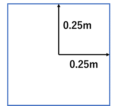
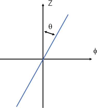
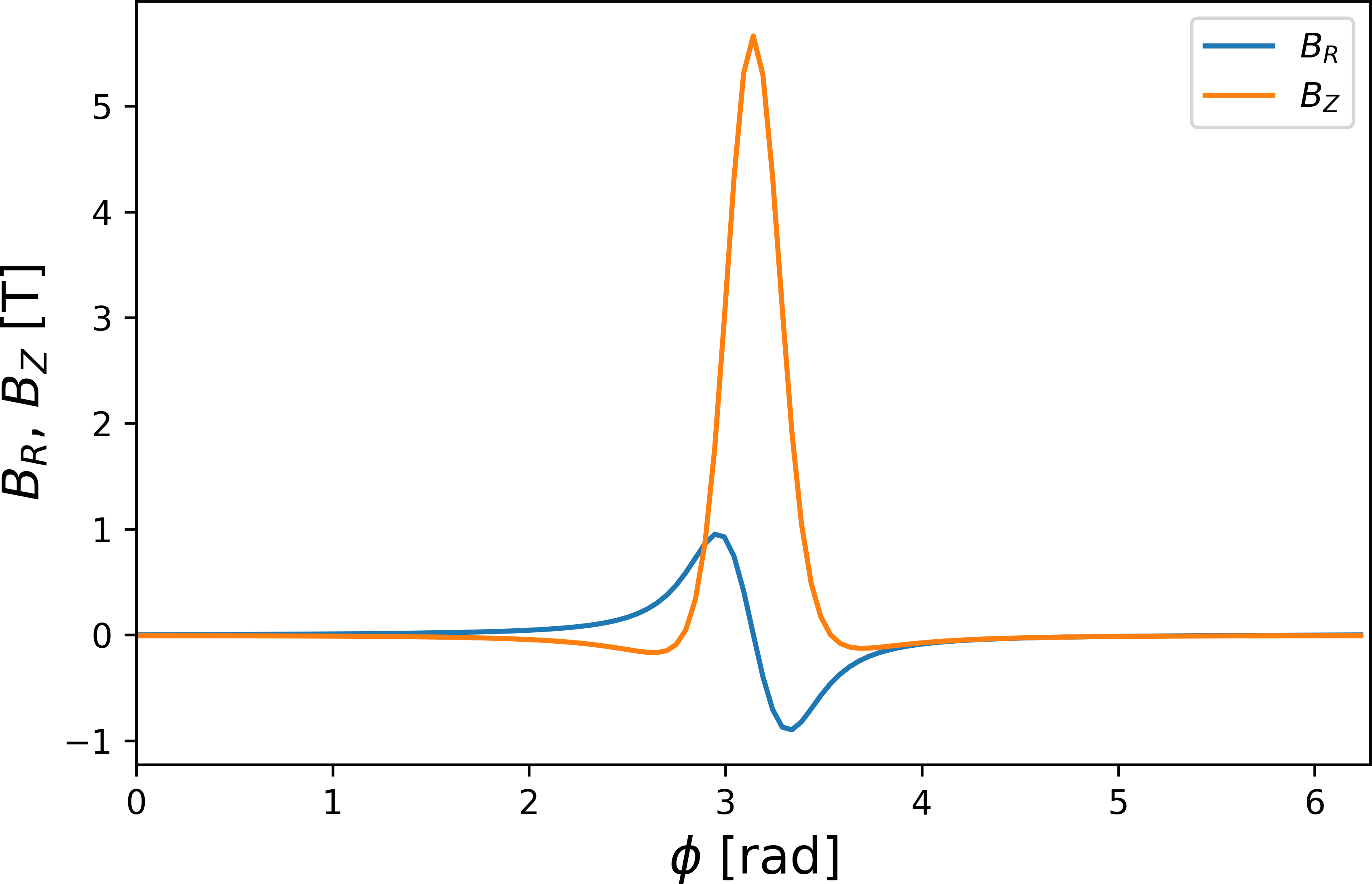
Here, the vacuum magnetic field produced by a tilted TF coil is considered. Figure 1 shows a configuration of a tilted TF coil. The size of the TF coil is 0.5 m by 0.5 m and the shape is the square on the - plane. The center of the squared TF coils is = 1 m. The size of the TF coil is decided from the vessel design of the J-TEXT tokamak. The tilting angle, , is 30 degree along the toroidal angle, . Figure 2 shows profiles of and along the toroidal angle, at = 1 m. The toroidal magnetic field is = 1 T at = 1 m, in other words, the current of the TF coil is estimated from the condition of = 1 mT. The tilting of the TF coil produces the both of and . In particular, phases of and are opposite, and this is a reason why the tilting of the TF coil can be a source of the error field to make the magnetic island in tokamak plasmas. The amplitude of is much higher than the amplitude of . If the amplitude of can be reduced by the axisymmetric poloidal field (PF) coil up to the same order of , the vacuum magnetic field by th tilted TF coil and PF coils is equivalent to the stellarator filed produced by the helical coil.
| (a) square shaped TF coil | (b) tilting angle, , |
|---|---|
 |
 |
II.2 A simple stellarator with tilted toroidal field and poloidal field coils
As discussed in above, the tilted TF coil can make the stellarator field without the toroidal current. Here, some reference designs are discussed. Figure 3 shows a schematic view of a coil geometry. This configuration consists of sixteen tilted TF coils (light green rectangles) and three pairs of axisymmetric poloidal coils (light blue curves). For a reference, the shape of the last closed flux surface of the plasma is also shown in the figure (colors indicate the magnetic field strength). The major radius of the TF coil is 1.0 m, and the size of the square is 0.5 m by 0.5 m. The is 1.0 mT, that is, the toroidal magnetic field, , at the center of the helical coil, = 1 m, is 1 T along the counterclockwise direction. The size and location of PF coils are also refereed from the J-TEXT tokamak.
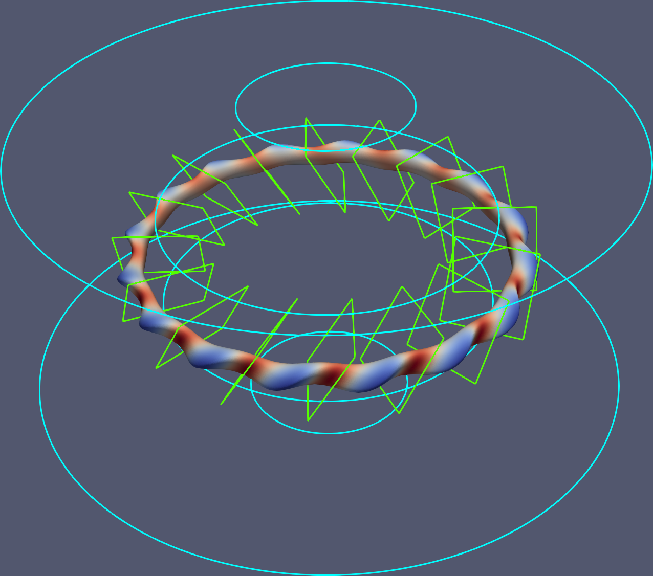
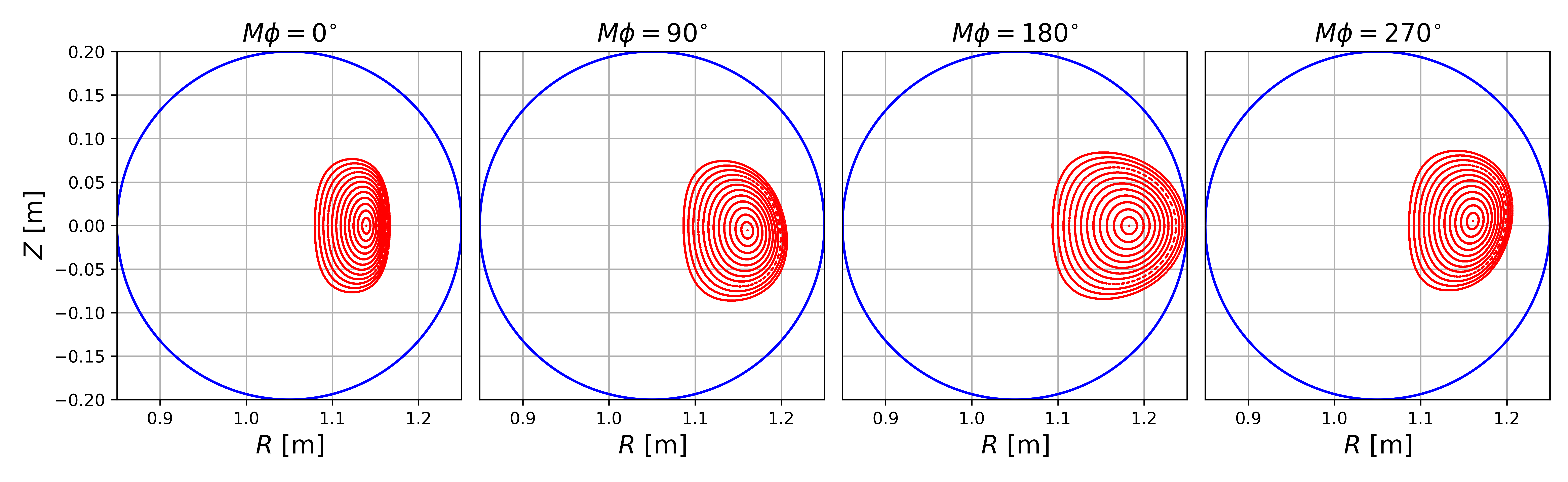
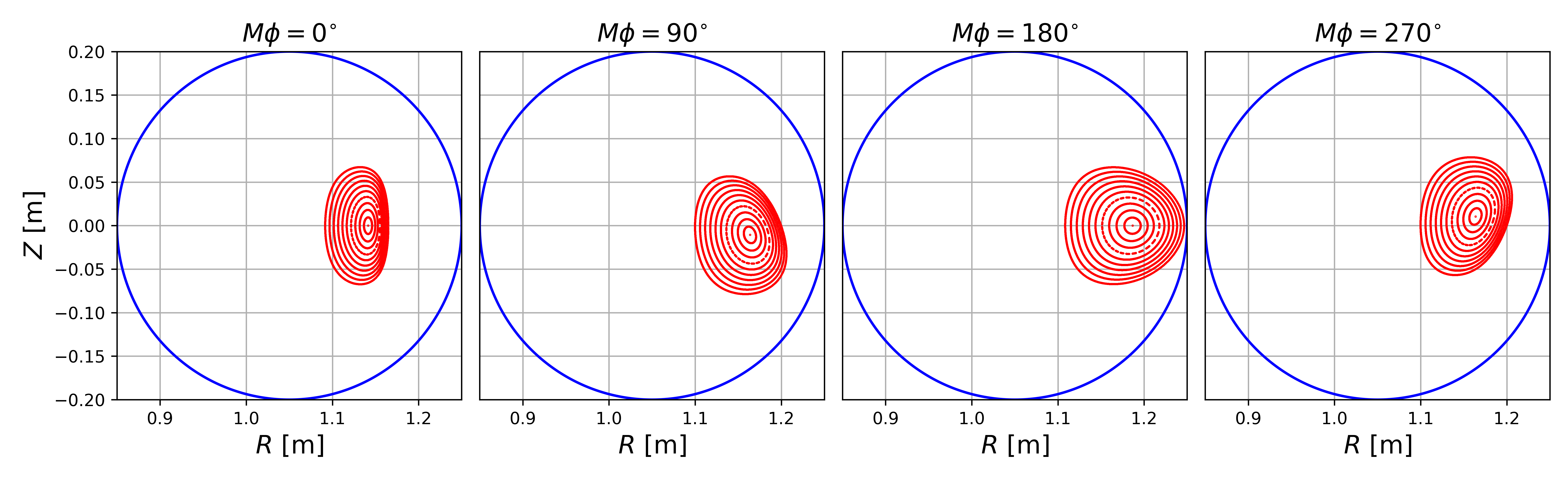
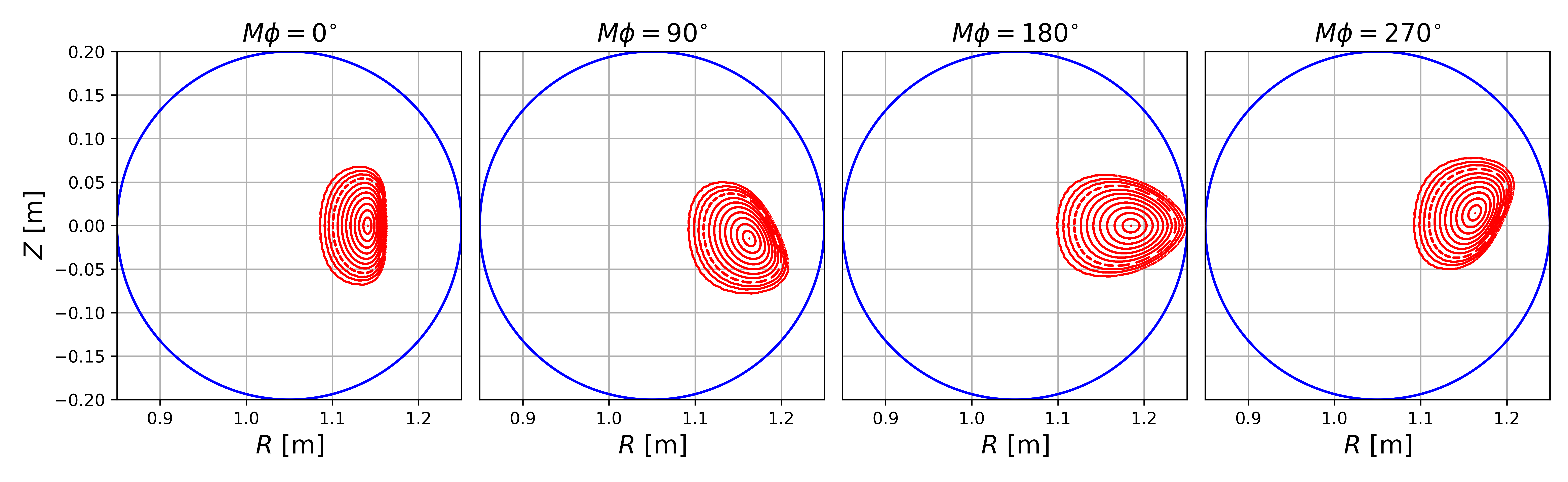
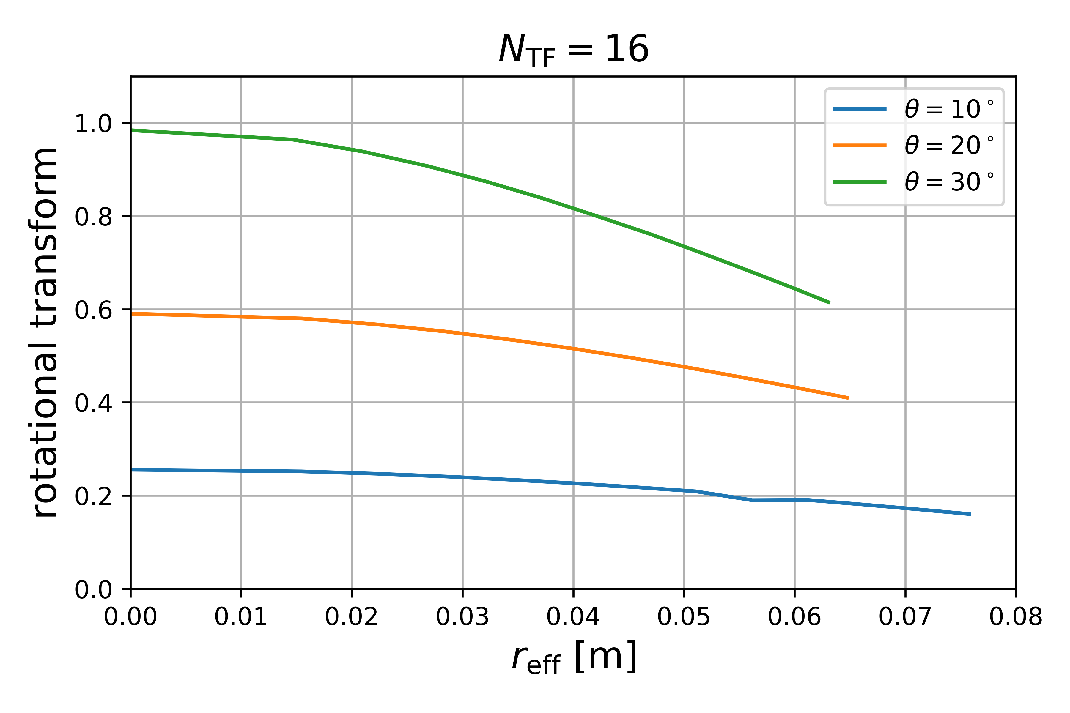
Figure 4 shows Poincaré plot of the vacuum magnetic field with different tilting angle, , to 10, 20, and 30 degree. A blue circle in each figures indicates the first wall. As shown in figures, clear flux surfaces appear, and the first wall limits the plasma volume, that is, this configuration is the limiter configuration. For each cases, the magnetic axis is helically deviates, and the deviation is proportional to the tilting angle, . In figure 5, profiles of the rotational transform, , as the function of the effective minor radius, , are plotted as configurations corresponding to figure 4. For a case of = 10 degree, the rotational transform is very low ( 0.2), and the magnetic shear is very weak. With increased the tilting angle, , the rotational transform increases, because the and increase. For another case of = 30 degree, the rotational transform on the magnetic axis increases up to the unity, and gradually decreases. In that case, the magnetic shear becomes strong. However, as shown in the figure, the plasma volume shrinks, because of the large helical deviation.
| (a) = 10 degree |
 |
| (b) = 20 degree |
 |
| (c) = 30 degree |
 |
II.3 Magnetic field spectrum on Boozer coordinate
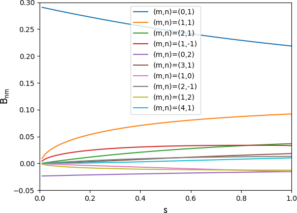
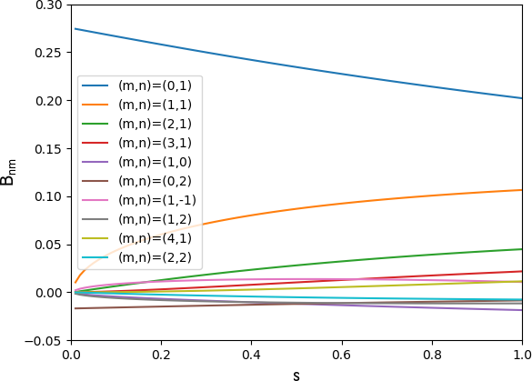
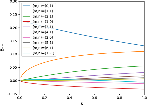
In order to understand characteristics of the magnetic configuration, the spectrum of the magnetic field is studied on Boozer coordinate Boozer (1982). The magnetic field spectrum on Boozer coordinate is calculated from the zero-beta 3D equilibrium by the VMEC code Hirshman (1983). Figure 6 shows the spectrum of the magnetic field, , on Boozer coordinate for = 10, 20, and 30 degree, respectively. The spectra omit the axisymmetric toroidal field component, . Since the magnetic field is mainly produced by the TF coil, the first dominant component is the mirror ripple (TF ripple), . The second dominant component is the helical ripple, . This is a similar nature to the quasi-isodaynamic configuration like W7-X. With increased the tilting angle, , the mirror ripple decreases, and the helical ripple increases. For a case of = 30 degree, the mirror and helical ripples are almost comparable in the plasma edge. That might reflect that the orbit property of the ion confinement will degrade because of the helical ripple loss. Other components are relatively small comparing with the mirror and helical ripples. These spectra are studied for only the vacuum field. For cases of = 10 and 20 degree, since the rotational transform is small, the Shafranov shift due to the finite- effect might be large. An impact of the finite- effect on Boozer spectrum must be studied.
| (a) = 10 degree | (b) = 20 degree | (c) = 30 degree |
|---|---|---|
 |
 |
 |
II.4 collisionless orbit property
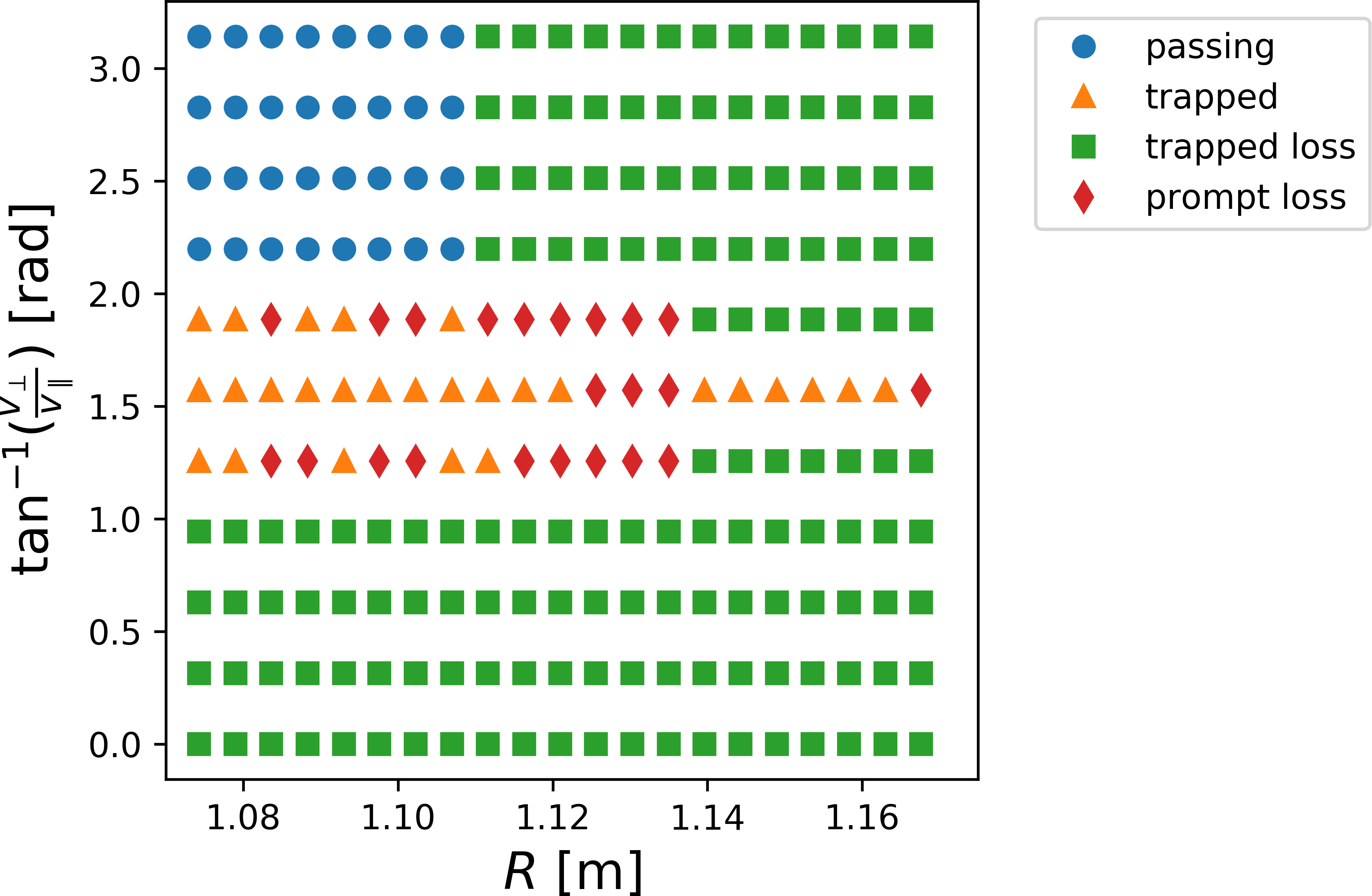
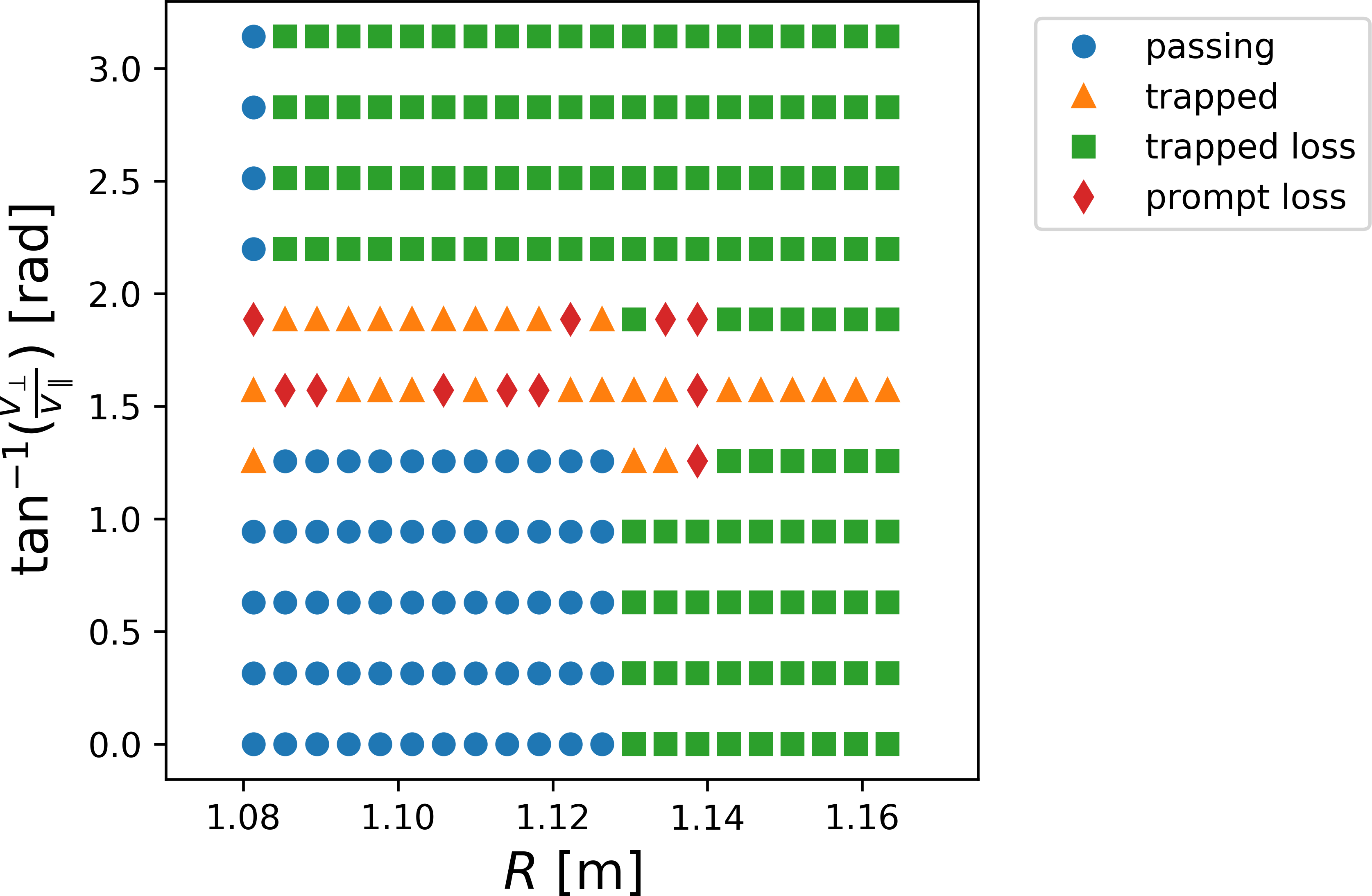
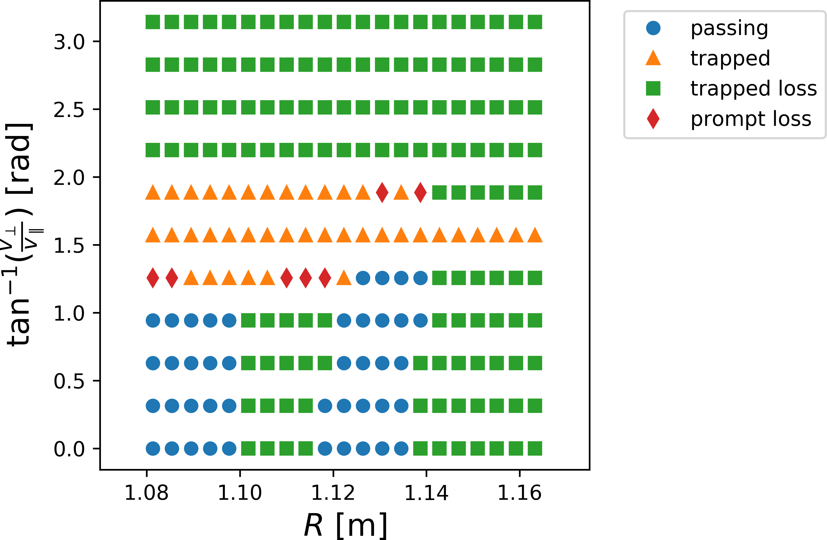
According to the spectrum of the magnetic field on Boozer coordinate, these configurations have a similar nature to the quasi-isodynamic configuration, that is, the confinement of the trapped particle improves due to the strong mirror ripple. On the other hand, for the small tilting angle, = 10 degree, the rotational transform is very small. In such a case, the poloidal drift width is very large. Therefore, the orbit surfaces deviates from the flux surface, and then, the prompt loss will increase. To confirm that hypothesis and estimate the orbit confinement quantitatively, the collisionless guiding-center orbit is studied for three cases. The guiding-center of the 100 eV proton is followed by the GCR code Suzuki et al. (2006) for the vacuum field. The starting points are set to the = 0 plane at the = 0. The pitch angle, , is scanned from 0 to . Figure 7 shows the loss cone for three cased of = 10, 20, and 30 degree, respectively. For a case of = 10 degree, due to the large poloidal drift width, the almost co-going orbit losses. The trapped ion with is confined in the inward of the torus, but that losses in the outward of the torus. For another case of = 20 degree, the confinement of the co-going ion improves, and small amount of the counter-going ion is confined. Also, the almost trapped ion with is confined. However, for the last case of = 30 degree, the number of confined co-going ion decreases, and all counter-going ions loss. The number of the trapped ion increases due to the increased helical ripple, and the almost trapped ion is confined. Since the orbit property is sensitive to the finite- effect, the orbit following calculation for the finite- equilibrium will be important.
| (a) = 10 degree | (b) = 20 degree | (c) = 30 degree |
|---|---|---|
 |
 |
 |
III Summary and outlook
This paper studied the simple design of the stellarator with tilted TF coils. Coupling the tilted TF coil and axisymmetric PF coil, the stellarator field produces. With tracing the magnetic field line for the vacuum field, the formation of clear and nested flux surfaces are confirmed. The rotational transform is proportional to the tilting angle of the TF coil, , and the magnetic shear is weak. The spectrum of the magnetic field on Boozer coordinate is studied. The stellarator with the tilted TF coils has a similar property to the quasi-isodynamic configuration, because the mirror ripple is a dominant component of the magnetic field spectrum. With changing the tilting angle of the TF coil, , the configuration is scanned. For a case of a low tilting angle, = 10 degree, the rotational transform is small and the magnetic shear is very weak. In such a case, the drift width of the proton orbit is large, and then the co-going ions cannot be confined. A small amount of the counter-going ion in the inward of the torus can be confined. However, for another case of = 20 degree, the rotational transform increases, and the confinement of the co-going orbit improves. Also, the confinement of the trapped ion for the pitch angle, , improves. However, for the last case of = 30 degree, the confinement of the co-going ions degrades again.
The design of the simple stellarator in this paper is studied for only the vacuum field. Since the magnetic shear is weak, the magnetic field might be sensitive to the finite- effect. Studies including the finite- effect is an important subject. Also, in this paper, we discussed only the tilted TF coils according to a simple rule, that is, the TF coil tilts along the toroidal angle, , direction. From a study of CNT, it was confirmed that the magnetic field is very sensitive to the small displacement of the coil set Zhu et al. (2018). Therefore, the optimization of the simple stellarator will be possible. Those studies are future subjects, and those will be reported in near future.
Acknowledgments
This work is supported by the NINS (National Institute of Natural Sciences) program of Strategic International Research Interaction Acceleration Initiative (Grant No. UFEX404), and State Key Laboratory of Advanced Electromagnetic Engineering and Technology (Grant No. AEET 2019KF002). Also, this work was partially supported by ’PLADyS’, JSPS Core-to-Core Program, A. Advanced Research Networks.
References
- John Wesson (2011) John Wesson, Tokamaks, fourth edi ed. (Oxford University Press, 2011) p. 832.
- Zohm (1996) H. Zohm, Plasma Physics and Controlled Fusion 38, 105 (1996).
- Loarte et al. (2003) A. Loarte, G. Saibene, R. Sartori, M. Becoulet, L. Horton, T. Eich, A. Herrmann, M. Laux, G. Matthews, S. Jachmich, N. Asakura, A. Chankin, A. Leonard, G. D. Porter, G. Federici, M. Shimada, M. Sugihara, and G. Janeschitz, Journal of Nuclear Materials 313-316, 962 (2003).
- Spitzer (1958) L. Spitzer, Physics of Fluids 1, 253 (1958).
- Boozer (2008) A. H. Boozer, Plasma Physics and Controlled Fusion 50, 124005 (2008).
- Boozer (2020) A. H. Boozer, Nuclear Fusion 60, 065001 (2020), arXiv:1912.06289 .
- Ho and Kulsrud (1987) D. D.-M. Ho and R. M. Kulsrud, Physics of Fluids (1958-1988) 30, 442 (1987).
- Grieger et al. (1989) G. Grieger, C. Beidler, and E. Harmeyer, Physics studies for helical-axis advanced stellarators (IAEA, International Atomic Energy Agency (IAEA), 1989).
- Anderson et al. (1995) F. S. B. Anderson, A. F. Almagri, D. T. Anderson, P. G. Matthews, J. N. Talmadge, and J. L. Shohet, Fusion Technology 27, 273 (1995).
- Klinger et al. (2017) T. Klinger, A. Alonso, S. Bozhenkov, R. Burhenn, A. Dinklage, G. Fuchert, J. Geiger, O. Grulke, A. Langenberg, M. Hirsch, G. Kocsis, J. Knauer, A. Krämer-Flecken, H. Laqua, S. Lazerson, M. Landreman, H. Maaßberg, S. Marsen, M. Otte, N. Pablant, E. Pasch, K. Rahbarnia, T. Stange, T. Szepesi, H. Thomsen, P. Traverso, J. L. Velasco, T. Wauters, G. Weir, T. Windisch, A. Kramer-Flecken, H. Laqua, S. Lazerson, M. Landreman, H. Maaßberg, S. Marsen, M. Otte, N. Pablant, E. Pasch, K. Rahbarnia, T. Stange, T. Szepesi, H. Thomsen, P. Traverso, J. L. Velasco, T. Wauters, G. Weir, T. Windisch, A. Krämer-Flecken, H. Laqua, S. Lazerson, M. Landreman, H. Maaßberg, S. Marsen, M. Otte, N. Pablant, E. Pasch, K. Rahbarnia, T. Stange, T. Szepesi, H. Thomsen, P. Traverso, J. L. Velasco, T. Wauters, G. Weir, and T. Windisch, Plasma Physics and Controlled Fusion 59, 014018 (2017).
- Chu et al. (1982) T. Chu, H. Furth, J. Johnson, C. Ludescher, and K. Weimer, Nuclear Fusion 22, 871 (1982).
- Merkel (1987) P. Merkel, Nuclear Fusion 27, 867 (1987).
- Funato et al. (1983) Y. Funato, I. Sakamoto, and H. Watanabe, Japanese Journal of Applied Physics 22, 1188 (1983).
- Bykov et al. (1989) V. E. Bykov, E. D. Volkov, and A. V. Georgievskij, Optimization studies of compact torsatrons (IAEA, International Atomic Energy Agency (IAEA), 1989).
- Todd (1990) T. N. Todd, Plasma Physics and Controlled Fusion 32, 459 (1990).
- Pedersen et al. (2004) T. S. Pedersen, A. H. Boozer, J. P. Kremer, R. G. Lefrancois, W. T. Reiersen, F. Dahlgren, and N. Pomphrey, Fusion Science and Technology 46, 200 (2004).
- Clark et al. (2014) A. Clark, M. Doumet, K. Hammond, Y. Kornbluth, D. Spong, R. Sweeney, and F. Volpe, Fusion Engineering and Design 89, 2732 (2014).
- Ge et al. (2009) Z. Ge, D. Yonghua, Z. Ming, Y. Kexun, Z. Xiaoqing, W. Zhijiang, H. Xiwei, P. Yuan, and J.-T. Team, Plasma Science and Technology 11, 439 (2009).
- Boozer (1982) A. H. Boozer, Physics of Fluids 25, 520 (1982).
- Hirshman (1983) S. P. Hirshman, Physics of Fluids 26, 3553 (1983).
- Suzuki et al. (2006) Y. Suzuki, H. Yamada, N. Nakajima, K. Watanabe, Y. Nakamura, and T. Hayashi, Nuclear Fusion 46, 123 (2006).
- Zhu et al. (2018) C. Zhu, S. R. Hudson, S. A. Lazerson, Y. Song, and Y. Wan, Plasma Physics and Controlled Fusion 60, 054016 (2018).